Proceedings of the American Control Conference Albuquerque, New Mexico June 1997 0-7803-3832-4/97/$10.000 1997 AACC
Virtual Sensors for Spark Ignition Engines Using Neural Networks Emil L. Hanzevack, Theresa W. Long, Chris M. Atkinson, and Michael L. Traver NeuroDyne Inc. One Kendall Square Cambridge. MA 02 139
[email protected]
Abstract The overall goal of this project is to design and develop an engine monitoring and control system for spark ignition engines that will help to reduce emissions and increase efficiency. Certain engine parameters are already measured by existing measurement sensors. Other parameters necessary or desirable for intelligent engine monitoring or control are not currently measured, either because those measurements would be too costly or too slow to be of use in real time. The approach is to use the suite of available sensor measurements along with neural networks with online learning capabilities to develop “virtual sensors” for the parameters that are needed but cannot be easily or rapidly measured. The data from these virtual sensors can then be used for performance monitoring and to make intelligent engine control decisions. A general aviation (GA) aircraft engine was used for data collection for this phase of the project. Three virtual sensors were developed in this project. These virtual sensors estimate parameters for pilot aid, diagnostics, and emission monitoring. High quality outputs were obtained for all parameters for normal operating conditions. The estimation errors ranged from +3% to f6%. This level of accuracy demonstrates feasibility of the virtual sensor concept for this application. 1. Introduction Many analyzers are generally not rugged enough or inexpensive enough for field implementation. For example, exhaust temperature and power are important operating parameters that are unmeasured on current GA engines. However, at a test site, where the analyzers can be installed as a stationary instrument, accurate measurements can be obtained. The engine operating conditions as well as the corresponding pollutant emissions can be recorded. A
neural net can be trained with supervised learning using measured engine operating conditions as input and the corresponding unmeasured operating parameters and pollutant emissions as the target output. When sufficient experiments are performed so that the operating range is well covered, the resulting neural net can be a reliable virtual sensor for the unmeasured operating parameters as well as for pollutant emissions. This neural net can then be used to predict exhaust temperature which can then be related to the power, which is also unmeasured. Therefore, the virtual sensor can serve as a surrogate for the dynamometer. The incentive for developing a virtual sensor system is to produce a set of measurement estimations to assist the pilot in a general aviation (GA) aircraft. For example, knowledge of the torque or power output of the engine can be used by the pilot for control maneuvers. Accurate torque measurement is diffidt to obtain on board, but can be obtained on a dynamometer in the laboratory. A neural network based virtual sensor can be trained using real engine data in the factory to estimate the torque output accurately. The main advantage of using a virtual sensor is that now one can have reliable estimated measurements which were not previously available. A second advantage is that virtual sensors take up very little space or payload compared to the hardware that would be needed to provide equivalent measurements. A third advantage is that the maintenance of a virtuail sensor is less demanding than for hardware. There are three applications of virtual sensors for a general aviation (GA) aircraft: pilot aid, diagnostics, and emission monitoring.
669
1. Pilot aid A candidate for virtual sensor output is power.
Knowledge of the power output of the engine can be used by the pilot for control maneuvers. Calculation of power requires measurement of torque. Accurate torque
~
Based on these three applications of virtual sensors, we have designed three neural networks: N",NNFP, and "E. The output of NNP is power. The output of NNFP is fuel pressure. The output of "Eis HC, CO, CO,, NOx, and the stoichiometric index k.
measurement is difficult to obtain on board, but can be obtained on a dynamometer in the laboratory, Consequently, accurate power determination can be obtained in the factory to train a neural network based virtual sensor to correctly estimate the power output. 2. Diagnostics Candidate virtual sensor outputs are fuel pressure, stoichiometric index h, and COz emission. These parameters provide indication of efficiency of fuel consumption and hence anticipated range. Fuel pressure and h can be measured on-board. But virtual sensors can be used to provide redundant parameters for fault detection related to the fuel pressure sensor. The stoichiometric index h corresponds to the on-board oxygen analyzer (EGO) measurement. Due to the leaded fuel used by GA aircraft, oxygen analyzers tend to malfunction after a while. A virtual sensor can be trained on board to mimic the oxygen sensor, and then can continue to function even after the oxygen sensor has deteriorated.
2. GA Engine Experiments
To collect experimental data for the neural networks, a Textron-Lycoming IO-360-B1E air-cooled aircraft engine was procured, instrumented, and operated on an engine dynamometer at the West Virginia University Engine Research Center (ERC). Performance, fuel efficiency, and emissions data were successfully sampled, recorded and stored upon a dedicated data acquisition computer for further analysis.
3 Emission estimation Emission estimation can be used for engine performance monitoring. Candidate virtual sensor outputs are HC, CO, and NOx. These estimates can also be used to fulfill anticipated future pollution control regulatory requirements. Emission measurement instrumentation is generally costly and not robust enough for on-board implementation, but a virtual sensor can be trained using sophisticatedemission analyzer in the laboratory.
Although a virtual sensor is a form of state estimator, it is distinguished from the general state estimator in that the same parameter can not appear in both the input and the output of the sensor. For example, a torque estimator using a history of the torque and the control for input is not a virtual sensor. This separation of input and output parameters is a necessity stemming from the application of virtual sensors. The three types of virtual sensors share one common characteristic: there is no on-line update of the sensor, either because there is no on-board instrumentation to provide a reference measurement for update, or because the virtual sensor operates independently of the on-board measurement for diagnostics purposes. A virtual sensor, of course, does have errors. These errors, if small, usually do not pose a problem because pilot aid or diagnostic tools put more stock on the trend than the actual magmtude of a parameter. Also, virtual sensors are subject to calibration or routine maintenance during off-service periods just like maintenance for a real sensor. This would prevent virtual sensors from becoming inaccurate over time.
The engine is a horizontally opposed, four cylinder, aircooled, general aviation aircraft engine, model number IO360-BlE, which incorporates mechanical fuel injection and employs a manual mixture control. The engine is rated for 160 hp at 2700 rpm and displaces 320 cubic inches with a compression ratio of 8.5 to 1. The ignition timing is set at 25' before top dead center and the firing order is 1-3-2-4. The fuel required is low lead aviation fuel. Sensors measured exhaust gas oxygen (UEGO), manifold air pressure (MAP), temperature at several points (inlet, cylinder, and exhaust), throttle position, fuel flow and mixture, and other relevant operating parameters. Four exhaust emissions were measured, three regulated (Hydrocarbons (HC), carbon monoxide (CO), and oxides of nitrogen (NOx)), and one non-regulated (Carbon dioxide (C02)). Exhaust emissions are measured &er dilution with ambient air in a dilution tunnel, in accordance with the Code of Federal Regulations for measurement of emissions from light duty vehicles, but a time deconvolution technique is applied to obtain quasi-real time exhaust emissions at the engine manifoId. This allows emissions to be directly correlated with engine parameters to show direct causal relationships between changes in engine operation and operating parameters and resultant engine emissions. This is a distinct advance in real time engine emissions measurement. Six sequences of test data were obtained at the laboratory. The engine experiments were conducted to excite the engine as much as possible to obtain rich information. Consequently, most sequences have a high content of transient conditions, as evidenced by the high oscillation of parameters such as MAP, throttle, and fuel mixture.
670
3. Virtual Sensor Development
Several neural network architectures have been investigated for all three applications. The evaluation criteria are: 1. generalization error, as indicated by the holdout set (a blind test set), 2. size of the network, with smaller size preferred, and 3. convergence speed. Convergence speed has lower priority as a selection criterion because training the virtual sensor is done off-line. Time is not a pressing issue unless time to convergence is extremely long. A series of tests were conducted so that the architecture having the smallest size (in terms of number of inputs and hidden nodes) among neural nets yielding similar holdout set accuracy was selected. Table 1 lists the input and output parameters for the three neural nets.
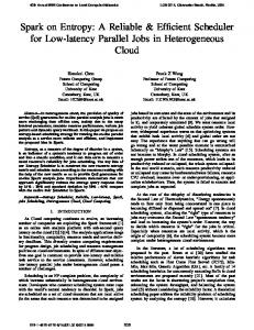
complex, and the best network architecture is a competitive net with two expert nets, shown in Figure 1. "E also requires a history queue of the input parameters. The input to the competitive net has the form of an ARMA (auto regression moving average) estimator. At each time stage, we use five sets of input with the input at 30At apart. Therefore, at time stage k, we use the input parameters at k, k-30, k-2x30, k-3x30, and k-4~30. This input format implicitly carries the 4th order derivative information, as the nth order derivative can be calculated using n+l terms equally spaced. Table 2. Neural Network Architecture for Virtual Sensors [I network I"p, parameter power fuel pressure NA NA expert nets 5 3 inputnodeso\r) data sets in input
1
Table 1, Input and Output Parameters of Three Neural Nets
parameter exhaust T ("C) cylinder head
oilT("C) MAP ma', throttle(%) fuel mix (%)
"Fp,
power
fuel pres in
in
out
"E, emission
nodes in lSt hidden layer (P) nodes in Yd hidden layer (Q) output nodes (R)
X
X
I 1 1;
1:
j
X
li
I emission 1 2 45
10
5
5
5 1
lo
1
I
5
The competitive network architecture was developed by NeuroDyne in a previous project for NASA Lewis Research Center. This neural network uses a divide and conquer strategy by modeling local systems (or regimes) separately with expert nets. A gating net classifies the input and sends the weighting factor corresponding to the membership of the input to each expert net. The weighted sum of the expert nets is the final network output. This type of classification is a soft classification. In contrast, conventional hard classification is binary, an item is either in a class or is not. Hard classification is usually not appropriate for dynamic systems. A point may lie where several classes overlap. Thus, it belongs to all of these classes but with different degrees of membership.
X
1
I"E,
X
x
x
I
time stages
*
"p,
,-I
I
X X
x
X
x
x
The neural network architectures selected are shown in Table 2. For NNP and NNFP,relatively small and simple two-hidden layer nets suffice. At each time stage, NNP and "P produce a power and a fuel pressure estimate based on the input parameters measured at that time stage. Mapping of the "E input to output is considerably more
The competitive net architecture was originally described by Jacobs et al. [l]. We have made significant changes to improve the implementation [ 2 ] . There are two main modifications. First, we added a hidden layer to the gating net. This hidden layer is necessary to provide additional connections to ensure that the classification problem is solvable. By adding a hidden layer, we provide the
67 1
necessary number of additional weights needed for a solution. The second modification is that we used the inner product of the error vector (weighted by the gating net output), instead of the mixture density maximum likelihood, as the objective function. For simple cases, we obtain similar results with either objective function. However, if we use a competitive net with a cascade of gating nets regulating the expert net output, our objective function is easier to track through the cascade. It was found that two expert nets are suf€icient for the current test data. Based on our experience on a variety of applications, we have rarely needed more than three expert nets.
computed based on the maximum magnitude of 150 kPa, it would be reported as a considerably smaller 1.3%. The virtual sensor for power is highly accurate with rms error less than 3.5 kW. Luh and Rizzoni reported that their torque estimator was not successful in estimating a sharp rise in load torque [3]. However, our results show that the virtual sensor can indeed accurately estimate a sharp rise in power. Since power is directly computed from torque by using speed, a power virtual sensor is equivalent to a torque sensor.
virtual sensor output rameter
4. Results
All of the neural nets were trained and tested using actual experimental data from the GA engine. The training and testing accuracy of all three nets was excellent. However, it is also necessary to reserve a holdout set (i.e., a blind set that the neural net has not previously seen) for rigorously evaluating the performance of various neural net architectures.
Very high quality virtual sensor outputs were obtained for the blind holdout set sequence #4. The output for sequence #2, while still acceptable, was somewhat less accurate than for sequence #4 because sequence #2 contains more transient swings. As previously mentioned, the engine experiments were conducted to purposely excite the engine as much as possible to obtain rich training information for the neural networks. Consequently, with the exception of sequence #4, all data sequences have a high content of transient conditions. This high transient content is an artifact of the experiments conducted, in an effort to obtain maximum information (richness of data) in minimum experiments, and is less encountered in an actual GA aircraft under normal operation. Therefore, we believe that the errors reported for sequence #4 would be closer to the level of accuracy achievable for actual on-board virtual sensors. The accuracy reported for sequence #2 can be considered to be the worst case errors. The rms estimation error for the holdout set sequence #4, considered to represent the typical operating case, is 2.56% for NNP, 3.97% for NNPF, and 5.70% for "E. The 111 scale rms error for each individual output is presented in Table 3. The percentage error quoted in this paper is based on one half operating range, to accommodate both plus and minus errors. This is an extremely conservative method of reporting errors. As an example, one half operating range of the fuel pressure is (150 - 90)/2 = 30 p a ) . An error of 3 2 @a would be reported as 6.7%. If the percentage error were
1 fuelpressure
operating range
I
I 0.0-165 I 90-150
neural net I id NNP
I I NNFP
rms error (full
I scale) I 1.9286 I 1.0214 1
0 . P a ) h HC (€99
II CO (ds)
0.3-1.3
0.0-1.2
I 0.0-13.0
"E "E
I "E
0.0232 0.0343
I 0.3077 11
Computation time on a SPARC-10 for the virtual sensors are 1.1 ms, 0.9 ms, and 5.7 ms, respectively. All of these times are well below the 50 ms (20 Hz) time frame characteristic of CA aircraft engine operation, indicating that real time operation is easily feasible.
5. Conclusions
Three virtual sensors were developed to estimate parameters for pilot aid, diagnostics, and emission monitoring. High quality outputs were obtained for all parameters for normal operating conditions. Estimation errors ranged from k3Y0to 16%. This level of accuracy demonstrates feasibility of the virtual sensor concept for this application. Estimation accuracy was within for power, 14% for fuel pressure, and k6% for h and emissions. Under a worst case scenario, where the engine is artificially perturbed frequently with transient conditions, the estimation accuracy is still within +4% for power, *7% for fuel pressure, and f l 1% for h and emissions. The main result of this project wilI eventually be a virtual sensor package to provide an engine monitoring system that can provide engine health monitoring and diagnostics, as well as help to reduce emissions and increase fuel efficiency. Future work would include final development and prototype
672
demonstration of this system, and would be followed by research and development of an intelligent engine control system. The intelligent monitoring and control techniques developed in this overall project will be applicable to a wide range of engines, including those using alternative fuels, operating under a variety of conditions. This technology will be transferable and available to general aviation engine manufacturers, as well as to other spark engine manufacturers, as a commercial product package. A similar virtual sensor concept is being pursued in parallel both for diesel and for hybrid electric vehicle engines.
6. References [l] Jacobs, R.A., M.I. Jordan, S.J. Nowlan, & G.E. Hinton, “Adaptive Mixtures of Local Experts”, Neural Cormtation, 3, 79-87, 1991. [2] T.W. Long and E.L. Hanzevack, “Hierarchical Competitive Net Architecture,” Neural Network Engineering in Dvlmamic Control Systems, K.J. Hunt, G.R.Irwin, and K. Warwick e&. Springer-Verlag London, 1995 [3] Luh, C.C., and G. Rizzoni, “Identification of a Nonlinear MIMO IC Engine Model during IN240 Driving Cycle for &-Board Diagnosis”, Proceedings of the American Control Conference, Baltimore, MarylanQ 1994.
node transfer functions J ? $ k softmax
@ logistic
0linear multiply
Flgure 1. Competitive Net
673