provided me with invaluable support for everything from strategic issues to technical ... proaches to flight control that allow aircraft to fly near obstacles. We show.
Vision-Based Control of Near-Obstacle Flight
THÈSE NO 4456 (2009) PRÉSENTÉE LE 17 JUILLET 2009 À LA FACULTÉ SCIENCES ET TECHNIQUES DE L'INGÉNIEUR LABORATOIRE DE SYSTÈMES INTELLIGENTS PROGRAMME DOCTORAL EN INFORMATIQUE, COMMUNICATIONS ET INFORMATION
ÉCOLE POLYTECHNIQUE FÉDÉRALE DE LAUSANNE POUR L'OBTENTION DU GRADE DE DOCTEUR ÈS SCIENCES
PAR
Antoine BEYELER
acceptée sur proposition du jury: Prof. H. Bleuler, président du jury Prof. D. Floreano, Dr J.-C. Zufferey, directeurs de thèse Prof. H. H. Bülthoff, rapporteur Prof. M. V. Srinivasan, rapporteur Prof. P. Vandergheynst, rapporteur
Suisse 2009
Acknowledgments
First, I would like to thank my thesis directors Prof. Dario Floreano and JeanChristophe Zufferey. I am most grateful to Dario for his trust, for his guidance throughout this thesis and for providing a great research environment. Since the beginning of my Master project back in 2002, Jean-Christophe Zufferey has provided me with invaluable support for everything from strategic issues to technical details. His contribution has been critical to the completion and the success of this thesis. I also thank him for revealing my interest in all things flying. I also thank my thesis referees Prof. Mandyam V. Srinivasan, Prof. Heinrich H. Bülthoff and Prof. Pierre Vandergheynst as well as my thesis committee president Prof. Hannes Bleuler. Special thanks go to Mandyam V. Srinivasan who allowed me to spend 3 months at his laboratory at the Australian National University. I am grateful to EPFL for providing a great studying and working environment, and to the Swiss National Science Foundation for funding my research (FNS grants nr. 200021-105545/1 and 200020-116149). I would like to thank my past and current colleagues at the Laboratory of Intelligent Systems (formerly Autonomous Systems Laboratory) for making the lab such an amazing place to work, and especially Jesper Blynel, Adrien Briod, Michael Bonani, Diego Federici, Yannick Fournier, Simon Harding, Sabine Hauert, Julien Hubert, Walter Karlen, Adam Klaptocz, Mirko Kovac, Daniel Marbach, Sara Mitri, Francesco Mondada, Andres Perez-Uribe, James Roberts, Daniel Roggen, Thomas Schaffter, Mathieu Scherz, Andrea Soltoggio, Timothy Stirling, Mototaka Suzuki, Danesh Tarapore, Markus Waibel, Yannick Weibel and Steffen Wischmann. I owe special thanks to Claudio Mattiussi, for his sig-
i
ii
ACKNOWLEDGMENTS
nificant contribution to my early work, to Stéphane Magnenat, for his invaluable collaboration in developing numerous pieces of software, to Severin Leven, for developing a flying platform that turned out to be critical to the success of this research and to Peter Dürr, for his comments on the manuscript. I would also like to thank Prof. Jean-Daniel Nicoud and André Guignard for their contribution to the miniature mechanics. Many students have contributed to this work. I wish to thank in particular Alexandre Habersaat and Okuary Osechas for their contribution to software tools. Also, not to be forgotten, the administrative assistants who are the ones that make it all work. Thanks to Dominique Etienne, Anouk Hein and Filomena Jacquier! I am very grateful to my family, Yves, Sylvie and Judith, for their unconditional support during my studies and my thesis. I also thank my friends for the many parties, the shared flat and the group holidays. They help me keeping from becoming a grown up! Finally, I would like to thank Emily for the thorough proof-reading and, most importantly, her support, her dedication and for being so close despite being so far.
Abstract
Lightweight micro unmanned aerial vehicles (micro-UAVs) capable of autonomous flight in natural and urban environments have a large potential for civil and commercial applications, including environmental monitoring, forest fire monitoring, homeland security, traffic monitoring, aerial imagery, mapping and search and rescue. Smaller micro-UAVs capable of flying inside houses or small indoor environments have further applications in the domain of surveillance, search and rescue and entertainment. These applications require the capability to fly near to the ground and amongst obstacles. Existing UAVs rely on GPS and AHRS (attitude heading reference system) to control their flight and are unable to detect and avoid obstacles. Active distance sensors such as radars or laser range finders could be used to measure distances to obstacles, but are typically too heavy and power-consuming to be embedded on lightweight systems. In this thesis, we draw inspiration from biology and explore alternative approaches to flight control that allow aircraft to fly near obstacles. We show that optic flow can be used on flying platforms to estimate the proximity of obstacles and propose a novel control strategy, called optiPilot, for vision-based near-obstacle flight. Thanks to optiPilot, we demonstrate for the first time autonomous near-obstacle flight of micro-UAVs, both indoor and outdoor, without relying on an AHRS nor external beacons such as GPS. The control strategy only requires a small series of optic flow sensors, two rate gyroscopes and an airspeed sensor. It can run on a tiny embedded microcontroller in realtime. Despite its simplicity, optiPilot is able to fully control the aircraft, including altitude regulation, attitude stabilisation, obstacle avoidance, landing and take-off. This parsimony, inherited from the biology of flying insects, contrasts with the complexity of the systems
iii
iv
ABSTRACT
used so far for flight control while offering more capabilities. The results presented in this thesis contribute to a better understanding of the minimal requirements, in terms of sensing and control architecture, that enable animals and artificial systems to fly and bring closer to reality the perspective of using lightweight and inexpensive micro-UAV for civilian purposes. Keywords: vision-based control, optic-flow-based control, obstacle avoidance, near-obstacle flight, autonomous unmanned aerial vehicle (UAV), microair vehicle (MAV)
Résumé
Les micro-drônes capables de voler de façon autonome en environnement urbain ou naturel permettent de nombreuses applications civiles et commerciales, telles que la gestion environnementale, la prévention des feux de forêt, la sécurité intérieure, la surveillance du trafic routier, l’imagerie aérienne, la cartographie ou le sauvetage. Des drônes encore plus petits, capables de voler à l’intérieur de maisons ou d’autres espaces clos, peuvent également servir à la surveillance, à l’assistance et au divertissement. Ces applications requièrent la capacité de voler près du sol et en présence d’obstacles. Les drônes existants exploitent le système GPS ainsi que des systèmes de navigation inertielle afin de contrôler leur vol, mais sont incapables de détecter ou d’éviter d’éventuels objets. Des capteurs de distance actifs tels que des radars ou des lasers pourraient être utilisés pour mesurer les distances aux obstacles, mais ils sont généralement trop lourds et consomment trop d’énergie pour être embarqués sur des systèmes légers. Dans cette thèse, nous nous inspirons de la biologie et explorons d’autres moyens de contrôler le vol près des obstacles. Nous démontrons que le flux optique peut être utilisé par des engins volants pour estimer la proximité des obstacles et nous proposons une nouvelle stratégie de contrôle visuel, appelée optiPilot, pour le vol près des obstacles. Grâce à optiPilot, nous avons mis au point les premiers micro-drônes capables de voler de manière autonome dans des environnements encombrés, aussi bien en intérieur qu’en extérieur, et sans utiliser de système de navigation inertielle ni de balise externe. La stratégie de contrôle nécessite seulement quelques capteurs de flux optique, deux gyromètres et un capteur de vitesse-air. Elle peut s’exécuter sur de minuscules microcontrôleurs en temps réel. En dépit de la simplicité de sa conception, optiPilot est capable de contrôler tous les aspects du
v
vi
RÉSUMÉ
vol, y compris l’altitude, l’attitude, l’évitement d’obstacle, l’atterrissage et le décollage. Cette économie de moyens, héritée de la biologie des insectes volants, contraste avec la complexité des systèmes utilisés jusqu’à présent, tout en offrant de plus nombreuses possibilités. Les résultats présentés dans cette thèse aident à mieux comprendre les mécanismes minimaux nécessaires aux animaux et aux systèmes artificiels pour voler. Ils constituent également un pas décisif vers la conception de micro-drônes légers et bon marché à usage civil. Mots clés: contrôle basé sur la vision, contrôle basé sur le flux optique, évitement d’obstacle, vol en environnement encombré, micro-drônes
Contents
Acknowledgments
i
Abstract
iii
Résumé
v
Contents 1
2
3
vii
Introduction
1
1.1
Introduction . . . . . . . . . . . . . . . . . . . . . . . . . . . . . . . .
1
1.2
State of the art . . . . . . . . . . . . . . . . . . . . . . . . . . . . . . .
3
1.3
Original contribution . . . . . . . . . . . . . . . . . . . . . . . . . . .
10
1.4
Organisation of the thesis . . . . . . . . . . . . . . . . . . . . . . . .
11
Vision-based state estimation
15
2.1
Introduction . . . . . . . . . . . . . . . . . . . . . . . . . . . . . . . .
15
2.2
Method . . . . . . . . . . . . . . . . . . . . . . . . . . . . . . . . . . .
16
2.3
Experimental setup . . . . . . . . . . . . . . . . . . . . . . . . . . . .
19
2.4
Results . . . . . . . . . . . . . . . . . . . . . . . . . . . . . . . . . . .
20
2.5
Conclusion . . . . . . . . . . . . . . . . . . . . . . . . . . . . . . . . .
24
Optic-flow-based proximity estimation in translation flight
27
3.1
Introduction . . . . . . . . . . . . . . . . . . . . . . . . . . . . . . . .
27
3.2
Fundamental properties . . . . . . . . . . . . . . . . . . . . . . . . .
28
3.2.1
Proximity estimation using optic flow . . . . . . . . . . . . .
28
3.2.2
Dynamics of translation flight . . . . . . . . . . . . . . . . .
30
vii
CONTENTS
viii
3.2.3
5
Optic flow extraction . . . . . . . . . . . . . . . . . . . . . . . . . . .
36
3.4
Optic flow derotation . . . . . . . . . . . . . . . . . . . . . . . . . . .
39
3.4.1
A posteriori derotation . . . . . . . . . . . . . . . . . . . . . .
39
3.4.2
A priori derotation . . . . . . . . . . . . . . . . . . . . . . . .
40
3.4.3
Gaze stabilisation . . . . . . . . . . . . . . . . . . . . . . . . .
40
3.4.4
Roll derotation . . . . . . . . . . . . . . . . . . . . . . . . . .
41
Conclusion . . . . . . . . . . . . . . . . . . . . . . . . . . . . . . . . .
42
3D flight control
43
4.1
Introduction . . . . . . . . . . . . . . . . . . . . . . . . . . . . . . . .
43
4.2
Control strategy . . . . . . . . . . . . . . . . . . . . . . . . . . . . . .
45
4.3
Experiments in simulation . . . . . . . . . . . . . . . . . . . . . . . .
49
4.4
Transfer to the real platform . . . . . . . . . . . . . . . . . . . . . . .
53
4.5
Discussion . . . . . . . . . . . . . . . . . . . . . . . . . . . . . . . . .
54
Generalisation and characterisation
59
5.1
Introduction . . . . . . . . . . . . . . . . . . . . . . . . . . . . . . . .
59
5.2
Control strategy . . . . . . . . . . . . . . . . . . . . . . . . . . . . . .
60
5.2.1
Selection of the viewing directions . . . . . . . . . . . . . . .
61
5.2.2
Mapping optic flow into control signals . . . . . . . . . . . .
61
5.2.3
Extension to non-circular sets of viewing directions . . . . .
66
5.3
Experimental setup . . . . . . . . . . . . . . . . . . . . . . . . . . . .
67
5.4
Results . . . . . . . . . . . . . . . . . . . . . . . . . . . . . . . . . . .
69
5.4.1
Obstacle avoidance in simulation . . . . . . . . . . . . . . . .
69
5.4.2
Flight stability in simulation . . . . . . . . . . . . . . . . . .
71
5.4.3
Flight stability with the real platform . . . . . . . . . . . . .
73
5.4.4
Obstacle avoidance with the real platform . . . . . . . . . .
80
Discussion . . . . . . . . . . . . . . . . . . . . . . . . . . . . . . . . .
84
5.5 6
34
3.3
3.5 4
Optic-flow-based proximity estimation in translation flight
Additional behaviours and situations
87
6.1
Introduction . . . . . . . . . . . . . . . . . . . . . . . . . . . . . . . .
87
6.2
Take-off . . . . . . . . . . . . . . . . . . . . . . . . . . . . . . . . . . .
87
6.3
Landing . . . . . . . . . . . . . . . . . . . . . . . . . . . . . . . . . .
89
6.4
Steering control . . . . . . . . . . . . . . . . . . . . . . . . . . . . . .
91
6.5
Flying with wind . . . . . . . . . . . . . . . . . . . . . . . . . . . . .
94
ix
7
6.6
Avoiding small obstacles . . . . . . . . . . . . . . . . . . . . . . . . .
6.7
Discussion . . . . . . . . . . . . . . . . . . . . . . . . . . . . . . . . . 102
Discussion and outlook
98
103
7.1
Accomplished work . . . . . . . . . . . . . . . . . . . . . . . . . . . 103
7.2
Biological comparison . . . . . . . . . . . . . . . . . . . . . . . . . . 104
7.3
7.4
7.2.1
Sensory modalities . . . . . . . . . . . . . . . . . . . . . . . . 104
7.2.2
Visual information processing . . . . . . . . . . . . . . . . . 105
7.2.3
Saccadic behaviour . . . . . . . . . . . . . . . . . . . . . . . . 107
7.2.4
Flight in cluttered and windy environments . . . . . . . . . 108
7.2.5
Altitude control and landing . . . . . . . . . . . . . . . . . . 109
7.2.6
Attitude stabilisation . . . . . . . . . . . . . . . . . . . . . . . 110
Limitations and future work . . . . . . . . . . . . . . . . . . . . . . . 111 7.3.1
Dependance on contrast . . . . . . . . . . . . . . . . . . . . . 111
7.3.2
Detection of small obstacles . . . . . . . . . . . . . . . . . . . 111
7.3.3
Frontal approaches . . . . . . . . . . . . . . . . . . . . . . . . 112
Conclusion . . . . . . . . . . . . . . . . . . . . . . . . . . . . . . . . . 113
A Test platforms
115
A.1 The MC2 microflyer . . . . . . . . . . . . . . . . . . . . . . . . . . . 115 A.2 The optiPilot test-bed . . . . . . . . . . . . . . . . . . . . . . . . . . . 117 B Simulation setup
121
B.1 Simulation software . . . . . . . . . . . . . . . . . . . . . . . . . . . . 121 B.2 Dynamics model . . . . . . . . . . . . . . . . . . . . . . . . . . . . . 121 B.3 Sensor models . . . . . . . . . . . . . . . . . . . . . . . . . . . . . . . 122 B.3.1
MC2 vision system . . . . . . . . . . . . . . . . . . . . . . . . 122
B.3.2
Optic mouse sensors . . . . . . . . . . . . . . . . . . . . . . . 122
B.3.3
Other sensors . . . . . . . . . . . . . . . . . . . . . . . . . . . 123
Bibliography
125
Curriculum vitæ
141
x
CONTENTS
1 1.1
Introduction
Introduction
Low-cost and lightweight micro unmanned aerial vehicles (micro-UAVs) capable of autonomous flight in natural and urban environments have a large potential for civil and commercial applications (Valavanis, 2007). Possible uses include environmental monitoring (e.g. air quality sensing, meteorological and scientific data harvesting, etc.), forest fire monitoring, homeland security, traffic monitoring, aerial imagery (e.g. real-estate, media, etc.), mapping, precision agriculture, ad hoc communication networks and search and rescue in rural or mountainous regions. Smaller micro-UAVs capable of flying within houses or small indoor environments have further applications in the domain of surveillance, search and rescue and entertainment. Large scale UAVs are now widely used for a variety of missions ranging from homeland security to military operations and have entered a time of maturity where they are increasingly replacing manned systems (Valavanis, 2007). Flying high in the sky, in airspace were navigation is coordinated by air traffic instances or even above the altitudes dedicated to commercial aviation, these systems rely mostly on GPS and AHRS (Attitude Heading Reference System) to estimate their state and control their position and orientation in space. However, they are unable to fly at low altitude because this would require them to sense and avoid obstacles such as buildings or trees, tasks which cannot be achieved using GPS and AHRS only. Similar state-based control is increasingly used with microUAVs (e.g. Beard et al., 2005; Valavanis, 2007). Procerus Technologies® Kestrel™ and MicroPilot® MP Series are examples of autopilot systems that weigh a few tens of grams. However, they still face difficulties with near-obstacle flight. In
1
2
INTRODUCTION
such situations, knowledge of position is difficult to obtain reliably using GPS, due to occlusions and signal reflections by buildings and other obstacles, and requires the additional knowledge of the 3D layout of the environment in order to steer free of collisions. A more efficient approach would be to continuously monitor the presence of obstacles and to steer the aircraft around them. The use of active sensors1 , such as laser range finders or sonars, has been considered for this task (Scherer et al., 2007, 2008), but they are generally heavy and power-consuming and therefore difficult to embed into platforms small and agile enough to safely navigate in cluttered environments. Flying autonomously indoors poses similar challenges – lack of GPS signals and presence of obstacles to be avoided – while considerably tightening the weight and power consumption constraints (Nicoud and Zufferey, 2002), which drastically limit the available computing power and precludes the use of active proximity sensors such as sonar, radar or laser range finders. This calls for the design of a specific sensor suite and a navigation strategy that allows collision-free navigation without relying on active sensing. The perspective of implementing autonomous control on current and upcoming gram-scale flying platforms (Fearing et al., 2002; Wood, 2008) completes the motivation for a sensor suite as lightweight and power-efficient as possible. Over the last decade, a significant amount of research showed that solutions to the challenges of autonomous flight in the vicinity of obstacles can be found by taking inspiration from biology (for reviews: Srinivasan and Zhang, 2004; Franceschini, 2004; Zufferey, 2008; Floreano et al., 2009). To quote Srinivasan and Zhang (2004), “a glance at a fly evading a rapidly descending hand or orchestrating a flawless landing on the rim of a teacup would convince even the most sceptical observer that this insect possesses exquisite visuomotor control, despite its small brain and relatively simple nervous system”. Flies use their eyes to extract information from the environment based on image motion (or optic flow) (Gibson, 1950; Franceschini, 1975; Land, 1997; Dudley, 2000), their halteres to measure rotation rates (Nalbach, 1993, 1994; Nalbach and Hengstenberg, 1994) and their hair and antennae to estimate airspeed (Dudley, 2000; Taylor and Krapp, 2008). Technology exists to implement these three sensory modalities in sub-gram-scale packages 1 Active
sensing refers to the process of emitting energy into the environment to make a mea-
surement, as opposed to passive sensing where only the energy pre-existing in the environment is used.
1.2. STATE OF THE ART
3
and can potentially be used to replicate biological principles to achieve autonomous flight with artificial platforms (Zufferey, 2008). Recent progresses in insect physiology have identified elements of the neural circuitry that enable the behaviours that amaze biologists and engineers alike, providing further hints to solve the challenges at hand (Taylor and Krapp, 2008). So far no demonstration of an aircraft capable of flying fully autonomously in unmodified environments without the help of GPS, AHRS or active distance sensors has been made. The work presented in this thesis aims at building on the recent advances in bioinspired control towards autonomous near-obstacle flight with micro-UAVs. To fit the constraints of lightweight flying platforms, we draw inspiration from the seminal work of Braitenberg (1984) and focus on reactive mechanisms that are derived from the properties of image motion and flight dynamics. Our ultimate goal is to better understand the minimal requirements, in terms of sensing and control architectures, that enable autonomous flight and demonstrate them with real flying platforms.
1.2
State of the art
Navigating in cluttered environments requires continuous monitoring of the proximity of surrounding obstacles such as terrain, trees, buildings, etc. and to steer away from them to avoid collisions. As discussed above, passive sensing such as vision is preferable to active sensing for the implementation of collisionfree navigation capabilities in lightweight aircraft. There are many ways in which vision can be used in autonomous systems, many of which are currently being investigated by scientists. However, classical computer vision is generally a computationally-intensive process that often requires the processing of high dimensional image data through a pipeline of operations such as contrast enhancement, edge detection, feature extraction and pattern recognition. The memory and computing power requirements of these processes typically preclude their use with lightweight flying platforms, in which resources are sparse and processing must be fast in order to keep up with the constant flow of incoming obstacles. For example, a significant body of work is dedicated to the use of visual servoing for flight control (Cheviron et al., 2007; Mahony et al., 2008; Shakernia et al., 2008, e.g.). However, while the nature of this processing makes it suitable for large hovering platforms, it is
4
INTRODUCTION
incompatible with lightweight aircraft. Similarly, the structure from motion problem, which consists of estimating both the structure of the environment and the state of the agent from visual input (Faugeras, 1992), is being tackled by a number of a researchers (Koenderink and van Doorn, 1990; Brodsky et al., 2000, e.g.). However, this process is typically computationally-intensive and has yet to be demonstrated on a phyisical flying platform. The observation that traditional computer vision is inadequate for the control of lightweight flying platform leads one to reconsider the entire sensing and control problem in the light of the biology of insect flight and the teachings of Braitenberg (1984). Such an approach has the potential to yield more compact solutions that are compatible with the lightest flying platforms. A large body of work, to which this thesis is the natural extension, has been dedicated to this alternative approach. Here, we review this domain in a roughly chronological order. Table 1.1 provides a summary of the various contributions discussed here. Huber and Bülthoff at the Max Plank Institude in Tübingen pioneered the idea of bioinspired obstacle avoidance based on optic flow. They used a simulated agent with simplified dynamics resembling Braitenberg’s vehicles and artificially evolved neural controllers (Nolfi and Floreano, 2000) that used pairs of optic flow detectors to navigate in textured corridors with obstacles (Huber et al., 1996; Neumann et al., 1997; Huber and Bülthoff, 2003). Neumann and Bülthoff extended this work in simulation and demonstrated the first completely autonomous vision-based flying agent with realistic dynamics – in this case viscous, insect-like dynamics (Neumann and Bülthoff, 2002; Neumann, 2003). This was achieved using a insect-like omnidirectional eye capable of perceiving optic flow and matched filters tuned by a learning mechanism. Attitude stabilisation was, however, not based on optic flow, but on colour gradients present in the simulated test environment. Franceschini’s team at Université de la Méditerranée in Marseille studied the optic-flow-based regulation of altitude and forward speed using a 3-degreeof-freedom rotorcraft attached to a pantographic arm (Netter and Franceschini, 1999, 2002; Ruffier and Franceschini, 2003, 2004, 2005, 2008), building on earlier work in simulation (Mura and Franceschini, 1994). They showed that both forward speed and altitude could be regulated using a single optic flow detector that was externally maintained vertical. These results were never translated onto a free-flying platform, which would have required solving the problem of atti-
1.2. STATE OF THE ART
5
tude estimation in order to control the detector’s viewing direction. In a parallel line of research, the team has been studying the control of a simulated hovercraft in a corridor (Serres et al., 2005, 2006a,b). The robot used two lateral optic flow detectors to centre in the corridor and to regulate its forward speed. However, the gaze direction was again artificially maintained at 90° with respect to the walls. Portelli et al. (2008) extended this strategy to demonstrate autonomous flight with a simulated honeybee, allowing regulation of altitude and forward speed as well as achieving corridor following by duplicating the existing corridor following strategy to the vertical direction. The remaining limitation lies in the assumption of an external gaze stabilisation mechanism that keeps the vision system level and aligned with the corridor at all times. This is problematic because the implementation of such a mechanism would require the agent to know its orientation, which is a difficult problem currently solved only by using a AHRS. Hrabar and colleagues at the University of Southern California used a simplified simulated helicopter (restricted to 2D and with kinematics similar to an unicycle) to study the optimal viewing direction for centring behaviour in corridors (Hrabar, 2006; Hrabar and Sukhatme, 2006). They found both theoretically and experimentally that if only two lateral optic flow sensors are used, it is optimal to set their viewing direction at 45° either sides of the aircraft’s main axis. This result contrasts with Franceschini’s work where optic flow sensors were always directed at 90°, both for altitude control and corridor following. Barrows and colleagues at Drexel University demonstrated the first in-flight use of optic flow for navigation on a real platform (Barrows and Neely, 2000; Barrows et al., 2001, 2002, 2003), quickly followed by Green (Green et al., 2003, 2004; Oh et al., 2004; Green and Oh, 2008). In both cases, either lateral obstacle avoidance or altitude regulation was demonstrated with fixed-wing platforms that were built with passive roll stabilisation. However, both teams provided only limited data to support these results and, while their achievements were remarkable, they did not include autonomous flight without human intervention. On the basis of his extensive work on honeybee flight control, Srinivasan and his team at the Australian National University implemented altitude control for cruise flight and landing approach on a fixed-wing aircraft (Chahl et al., 2004). While functional, the results of these experiments were limited because of the
Author
First Fully External publ. auton. aids
Huber et al.
1996
yesa
–
Platform
Demonstrated behaviours
References
artificial agent
OA, CEN, ALC
Huber et al. (1996); Neumann et al.
6
Table 1.1: State of the art of vision-based control of near-obstacle flight.
(1997); Huber and Bülthoff (2003)
Ruffier et al.
1999
yes
–
2D rotorcraft
FWD, ALC
Netter and Franceschini (1999, 2002); Ruffier and Franceschini (2003, 2004, 2005, 2008)
Barrows et al.
2000
no
–
fixed-wingb
OA
Barrows and Neely (2000); Barrows et al. (2001, 2002, 2003)
Neumann et al. 2002
yesa
–
insect (viscous)
–
fixed-wingb
OA, ALC, ATC
Neumann and Bülthoff (2002); Neumann (2003)
Green et al.
2003
no
OA,
ALCc
Green et al. (2003, 2004); Oh et al. (2004); Green and Oh (2008)
Chahl et al.
2003
yes
ocelli
fixed-wing
no demonstration Chahl et al. (2003); Thakoor et al. (2003, 2004)
2004
no
–
fixed-wing
ALC
Chahl et al. (2004)
Muratet et al.
2005
yesa
GPS/AHRS
helicopter
OA, CEN
Muratet et al. (2005)
Barber et al.
2005
yes
GPS/AHRS
fixed-wing
LDG
Barber et al. (2005, 2007)
Serres et al.
2005
yesa
–
hovercraft
FWD, CEN
Serres et al. (2005, 2006a,b)
Continued on next page...
INTRODUCTION
Chahl et al.
Zufferey et al.
2005
no
–
Platform
Demonstrated behaviours
References
fixed-wingb
OA
Zufferey (2005); Zufferey and Floreano (2005, 2006); Zufferey et al. (2006b, 2007)
Zufferey et al.
2005
yes
ALT
blimp
OA
Zufferey (2005); Zufferey et al. (2006a)
Hrabar et al.
2005
no
GPS/AHRS?
helicopter
CEN
Hrabar and Sukhatme (2003, 2004);
1.2. STATE OF THE ART
Author
First Fully External publ. auton. aids
Hrabar et al. (2005); Hrabar (2006)
Hrabar et al.
2006
noa
–
unicycle
CEN
Hrabar (2006); Hrabar and Sukhatme (2006)
Griffiths et al.
2006
yes
GPS/AHRS
fixed-wing
OA, CEN
Griffiths et al. (2006, 2007)
Portelli et al.
2008
yesa
–
insect (viscous)
FWD, CEN, ALC
Portelli et al. (2008)
Hyslop et al.
2008
yesa
Roll
helicopter
FWD, CEN, ALC
Hyslop and Humbert (2008)
helicopter
FWD, CEN
Humbert et al. (2009)
Humbert et al.
2009
yes
Vicond
Chapter 4
2007
yes
–
fixed-wingb
OA, ALC, ATC
Chapter 5
2009
yes
–
fixed-wing
OA, CEN, ALC, ATC, LDG, Take-off, Steering
OA: obstacle avoidance; FWD: forward speed regulation; CEN: centring; ALC: altitude control; ATC: attitude regulation; LDG: landing. a In simulation only. b Roll angle passively stabilised. c Behaviours demonstrated separately. d The Vicon™ tracking system was used to provide the functionality of an AHRS.
7
8
INTRODUCTION
spurious optic flow generated by pitch rotation. This strategy was reused by Thakoor and colleagues for altitude control over flat desert ground (Chahl et al., 2003; Thakoor et al., 2003, 2004) together with an attitude regulation scheme based on insect ocelli, which are able to perceive light gradient and polarisation pattern of the sky (Schuppe and Hengstenberg, 1993; Wellington, 1974). Unfortunately, these cues are not available indoors and they provided no detailed data on these experiments that allows to assess their functionality let alone their robustness. In our laboratory, and during the course of his thesis, Zufferey demonstrated two separate platforms capable of autonomous vision-based obstacle avoidance (Zufferey, 2005, 2008). The first one, an indoor fixed-wing platform, used two optic flow sensors to avoid walls that displayed strong contrasts, while altitude was manually controlled (Zufferey and Floreano, 2005, 2006; Zufferey et al., 2006b, 2007). The second platform, an indoor blimp, was also capable of avoiding contrasted walls while maintaining its altitude using an active distance sensor (Zufferey et al., 2006a). The blimp used an artificially evolved contrast-based strategy, rather than optic flow, that had the disadvantage of being dependant on the frequency of the contrast pattern present on the wall. The studies presented so far undoubtedly prove the pertinence of using optic flow for flight control. However, none of them have achieved fully autonomous behaviour on a real free-flying platform. Only altitude control or lateral obstacle avoidance was studied at a time. There has also been a more or less explicit tendency to break up the control into separate behaviours, such as lateral obstacle avoidance or altitude control, as most teams tackled only one aspect of flight, leaving the rest to manual control or other artificial stabilisation means. These results were convincing enough to attract attention from teams primarily concerned with state-based flight control. Their approach, based mainly on the use of GPS and AHRS, is problematic for near-obstacle flight as it does not enable the perception and avoidance of obstacles. In addition, this approach is generally too power-consuming and computationally heavy to be embedded in lightweight platforms. It was therefore tempting to include some optic-flowbased behaviours to complement the existing state-based control. Muratet and colleagues were the first to demonstrate this idea by using a realistic simulated helicopter that was able, on top of its state-based low-level control, to avoid obstacles and exhibit centring behaviour in urban environment, thanks to a
1.2. STATE OF THE ART
9
forward-pointing camera and optic flow extraction (Muratet et al., 2005). Altitude and attitude were regulated using a GPS and an AHRS. Beard and his team at Brigham Young University fitted their fixed-wing platforms with optic flow sensors to regulate altitude and control landing (Barber et al., 2005, 2007) as well as to detect obstacles in order to avoid them by deviating from the planed GPS trajectory (Griffiths et al., 2006, 2007). In each case, the position of the platform was controlled based on GPS, with tight control loops regulating the attitude based on the output of an AHRS. Finally, Hrabar et al. (2005) used a combination of optic flow and stereo vision to allow a real helicopter to centre in urban canyons, albeit providing limited information on how this was integrated with the low-level control loops. These studies are interesting because they demonstrate that optic flow can usefully augment existing state-based autonomous platform with capabilities like obstacle avoidance or altitude control. Though autonomous and well documented in general, the above-mentioned demonstrators always relied on state estimation using relatively expensive and heavy inertial sensing and a lot of computational power. Finally, Humbert recently developed a control-theoretic framework based on wide-field integration neural architectures of insects (Wehner, 1987; Egelhaaf and Borst, 1993a,b; Krapp et al., 1998; Krapp, 2000). Initially demonstrated with simulated 2D agents (Humbert et al., 2005a,b,c; Humbert and Frye, 2006) and later transferred to a real wheeled robot capable of centring and regulating its forward speed in a corridor (Humbert et al., 2007), this framework was then applied to two separate flying platforms. The first one is a simulated helicopter capable of autonomous corridor following, altitude control and attitude regulation using 3 orthogonal 360° optic flow sensor rings (Hyslop and Humbert, 2008). However, only a single run of simulation has been documented and the roll angle was assumed to be measured by an undefined external system. The second demonstration involved a real helicopter capable of centring in an indoor corridor with contrasted walls using a single 360° ring of 6 optic flow sensors (Humbert et al., 2009). While the helicopter was free-flying, it still relied on an external Vicon™ visual tracking system to control the attitude angles as well as the lateral velocity. The altitude was not explicitly regulated and remained stable thanks to the ground effect. While the feasibility of optic-flow-based near-obstacle flight has clearly been demonstrated by these studies, they still have limitations in one way or another:
10
INTRODUCTION
• dependance on a GPS and/or an AHRS (Muratet et al., 2005; Barber et al., 2007; Hrabar et al., 2005; Griffiths et al., 2007; Hyslop and Humbert, 2008; Humbert et al., 2009); • dependance on external gaze stabilisation systems to compensate for the rotations of the aircraft (Ruffier and Franceschini, 2005; Serres et al., 2006a,b; Portelli et al., 2008); • partial autonomy only, with assistance of a human pilot (Barrows et al., 2003; Green et al., 2004; Chahl et al., 2004; Zufferey and Floreano, 2005, 2006), a ground-attached artificial system (Ruffier and Franceschini, 2005) or a distance sensor (Zufferey et al., 2006a); • demonstration in simulation only (Muratet et al., 2005; Serres et al., 2006a,b; Hyslop and Humbert, 2008), sometimes with unrealistic dynamics model (Huber and Bülthoff, 2003; Neumann and Bülthoff, 2002; Portelli et al., 2008; Hrabar and Sukhatme, 2006). In this thesis, we demonstrate that the combination of bioinspired sensory modalities and processing with simple reactive control strategies inspired from Braitenberg (1984) is sufficient to overcome all of these limitations towards fully autonomous collision-free flight on a real aircraft, including altitude and attitude regulation, obstacle avoidance, take-off and landing, and steering.
1.3
Original contribution
This thesis can be classified in the emerging domain of biomimetic robotics, which sits at the intersection between biology and engineering (Nolfi and Floreano, 2000; Zufferey, 2008; Floreano and Mattiussi, 2008). Our aim is to understand the minimal mechanisms required in terms of sensing and control architecture to enable near-obstacle flight. Our contribution includes reactive control strategies that allow fully autonomous flight in the vicinity of obstacles using only lightweight passive sensors, i.e. a low-resolution vision system, rate gyroscopes and an airspeed sensor, excluding GPS, AHRS or any other computationally-intensive sensing or processing technology. We also contribute simulated and real prototypes capable of autonomous flight to demonstrate and
1.4. ORGANISATION OF THE THESIS
11
characterise the capability of the control strategies we propose. Specifically, this thesis contributes: • a vision-based strategy to estimate state variables such as altitude and pitch angle (chapter 2); • a control strategy that allows for fully autonomous flight control using only a vision system, two rate gyroscopes and an airspeed sensor and its application to a real 10-gram microflyer (chapter 4) • the generalisation and characterisation of this control strategy in simulation (chapter 5); • a simulated and real 400-gram micro-UAV capable of autonomous nearobstacle flight in natural environments, including altitude regulation, attitude stabilisation, obstacle avoidance, take-off, landing and steering (chapters 5 and 6 and appendix A).
1.4
Organisation of the thesis
The organisation of the present thesis follows the development of the proposed control strategy and aims to accompany the reader through the refinement of our methodology. The dissertation is organised into the following chapters. • Chapter 2 Vision-based state estimation
Facing the problem of control-
ling an aircraft using only visual and inertial sensing, it is at first tempting to develop a methodology to derive state information directly from the sensory data, in order to then apply the control theory to regulate it. In this chapter we propose a methodology and apply it to directly estimate altitude and pitch angle from images that can be acquired by a simple vision system compatible with indoor flight. From this study, we conclude that, although state variables like altitude and pitch angle can indeed be extracted from raw visual data, the related computational requirements makes the process difficult to integrate such a system into lightweight platforms. This is contrary to optic-flow-based proximity estimation and simpler reactive control strategies. This observation leads one to wonder whether proximity information alone is sufficient for autonomous control,
12
INTRODUCTION
bypassing the step of estimating the positional and angular state of the aircraft. The remaining of the dissertation aims at answering this question. • Chapter 3 Optic-flow-based proximity estimation in translation flight Before studying optic-flow-based control strategies, this chapter discusses how the properties of optic flow can be exploited to detect obstacles. We show that by taking into account the characteristics of the flight dynamics, optic flow can be directly interpreted as proximity to objects in the environment. We also review the technologies, methods and issues related to optic-flow-based proximity estimation in micro-UAVs. • Chapter 4 3D flight control
In this chapter, we propose to extend 2D
obstacle avoidance schemes described in previous work to the third dimension by considering the pitch control as an obstacle avoidance problem instead of an altitude control problem. We show that an aircraft can remain airborne by treating every object in the environment as obstacles – even the ground – and avoiding them, without the need to estimate its position and orientation. We use this principle to demonstrate autonomous flight with a simulated indoor microflyer and transfer the resulting control strategy to a real, 10-gram platform. • Chapter 5 Generalisation and characterisation
The 3D navigation sch-
eme presented in chapter 4 represents a significant paradigm shift compared to traditional autopilots, which use position and orientation estimates for the control, or previous work on microflyers, which attempted to separate altitude control from obstacle avoidance. In this chapter, we propose a generalisation of this 3D obstacle avoidance strategy, which we call optiPilot, and characterise it using both a simulated and a real outdoor fixed-wing platform. • Chapter 6 Additional behaviours and situations
In this chapter, we dis-
cuss how optiPilot can be used to implement additional behaviours, including take-off, landing and lateral steering. We also study the behaviour of optiPilot in wind conditions and its performance at avoiding small obstacles. . Finally, we characterise the performance of optiPilot for the avoidance of small obstacles using a space-like boundless environment that has neither
1.4. ORGANISATION OF THE THESIS
13
gravity nor ground. • Chapter 7 Discussion and outlook
We conclude this thesis with a dis-
cussion of the main results and their significance for biologists as well as proposals for future work. • Appendices
The appendices provide a technical description of our test-
beds (appendix A) and the simulation setup used to characterise our control strategy (appendix B).
14
INTRODUCTION
2
Vision-based state estimation
Note: this chapter is based on the following publication: A. Beyeler, C. Mattiussi, J.-C. Zufferey, and D. Floreano (2006). Vision-based altitude and pitch estimation for ultralight indoor aircraft. In Proceedings of the 2006 IEEE International Conference on Robotics and Automation (ICRA’06), pages 2836–2841.
2.1
Introduction
Since the optic flow perceived by a free-flying agent depends on distance to obstacles, several studies have tried to use it to estimate altitude. However, this did not lead to satisfactory results, either because the vision system was artificially maintained vertical in a way that is not realistic for free-flying platforms (Ruffier and Franceschini, 2005; Srinivasan et al., 2000), or because the attitude angles and rotation were ignored, leading to significant errors on the estimate (Barrows et al., 2001, 2002, 2003; Green et al., 2003, 2004; Chahl et al., 2004). In addition, they used various methods for estimating optic flow that were not always well motivated, such as elementary motion detectors that have the intrinsic property to respond non-linearly to image motion (Ruffier and Franceschini, 2005). This chapter describes our early attempt to solve simultaneously both the issue of altitude control and the limitations of using specific methods of optic flow extraction. Instead of first estimating optic flow before using it for altitude estimation and control, we propose a method where both altitude and pitch angle can be estimated directly from the raw signals provided by lightweight and inexpensive passive sensors including a 1D image sensor, a rate gyroscope and an airspeed sensor. Both the altitude and pitch angle estimates are directly
15
16
VISION-BASED STATE ESTIMATION
relevant to altitude control and would allow to apply classical control theory for the flight regulation (Stevens and Lewis, 2003). The next section presents the theoretical ground of our method. The simulations we performed to assess the model and their analysis are presented in section 2.3 and 2.4. Finally, in section 2.5, we comment the results and discuss why the limitations of this strategy lead us to favour proximity-based control strategies instead of state-based ones for the rest of our work.
2.2
Method
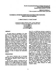
Instead of first estimating optic flow and then estimating altitude and pitch from it, we propose basing altitude and pitch estimation on the raw sensory data provided by an image sensor, rate gyroscopes and an airspeed sensor. To reduce the complexity of the problem, we simplified it by assuming that the aircraft has a null bank angle (the angle about the roll axis, i.e. the longitudinal axis of the airplane) at all times and that the projection of its trajectory on the ground is a straight line. This reduces the problem to two dimensions, as represented in figure 2.1. Furthermore, the ground is assumed to be planar and free of obstacles, and the air to be still. Under these assumptions, altitude and pitch can be estimated by minimising the difference between an interpolated image and the actual image obtained by the sensor. This approach is similar to the image-interpolation algorithm (I2A) proposed by Srinivasan (1994), but instead of evaluating image motion we directly estimate the parameters we want to measure. Two images f and f 0 are grabbed from the vision sensor at time t and t + ∆t. Meanwhile, the other sensors are used to measure the microflyer velocities1 v x and vy , and pitch rate ω, which are assumed to be constant during the time interval ∆t. Then, from f , v x , vy , ω and ∆t, an interpolated image fˆ0 (Θ, h) corresponding to f 0 and function of the altitude h and the pitch Θ is calculated. Finally, Θ and h are optimised so as to minimise the square error between the interpolated image fˆ0 (Θ, h) and the actual image f 0 . 1 In
principle, the anemometer provides only the speed along the aircraft’s main axis. The
velocity vy can be interpolated based on previous altitude estimations and used, together with the anemometer and previous pitch estimations, to estimate v x .
2.2. METHOD
17
y
y
h + vy · ∆t } t h
i−1
l
0 I
i
i+1 x
0
Iˆ!
! "# $ vx · ∆t
l!
x
vy
I!
ω
0
t + ∆t
h!
l−
vx
velocities
l l+ x ! "# $ vx · ∆t + l!
Figure 2.1: Geometrical layout of the problem. The top graphs represent the airplane position in space at time t and t + ∆t. The bottom graph shows how the ground texture intensity, noted I ( x ), is interpolated, based on the intensity of the neighbouring pixels. l, l + and l − correspond to the position on ground sampled by pixels i, i + 1, and i − 1, respectively. The local slope of the intensity function
is estimated using I (l − ) and I (l + ), and is used to interpolate I (v x · ∆t + l 0 ) from I (l ), leading to the estimate intensity Iˆ(v x · ∆t + l 0 ) (see equation 2.3). We model the vision sensor as a perfect, circular camera whose pixels sample the ground image at its intersection with their looking direction, noted θi for the i-th pixel (this angle has a negative value, since the camera points downward). The ground light intensity is noted I ( x ), where x is the distance on ground calculated from the origin of the coordinate system, which is underneath the microflyer at time t. Then, the image f can be expressed as f (θi ) = I (l ) = I (h · tan(θi + Θ +
π )) = I (h · k(θi , Θ)), 2
(2.1)
where, by definition, k(θ, Θ) = tan(θ + Θ + π/2) = −1/ tan(θ + Θ). Similarly,
18
VISION-BASED STATE ESTIMATION
the second image is f 0 (θi ) = I (v x · ∆t + l 0 ) = I (v x · ∆t + (h + vy · ∆t) · k (θi , Θ + ω · ∆t)). (2.2) As represented in the bottom part of figure 2.1, we compute an interpolated image fˆ(θi ) based on the linearisation of I ( x ) around x = h · k(θi , Θ). Using the symbols defined in figure 2.1, we can write
I (l + ) − I (l − ) Iˆ(v x · ∆t + l 0 ) = I (l ) + · (v x · ∆t + l 0 − l ). l+ − l−
(2.3)
Of course, this approximation is acceptable only under certain conditions. First, the interpolated point v x · ∆t + l 0 should lie within the range [l − ; l + ] or close to
it. This means that either the velocities (especially the rotational velocity) are limited, or the time interval ∆t is kept short. Second, it limits the acceptable spatial frequencies for the ground texture, since the intensity should be close to linear in the range [l − ; l + ]. In practice, it is relatively easy to cut higher frequencies, for example by defocusing the vision system, but the image must contain some low frequencies for this method to be feasible. Based on equation 2.1 and (2.2), we can rewrite equation 2.3 using, for simplicity, f (θi ) = f i and k (θi , Θ) = k i (Θ) fˆ0 i = f i +
f i +1 − f i −1 · h · (k i+1 (Θ) − k i−1 (Θ))
� · v x · ∆t + (h + vy · ∆t) · k i (Θ + ω · ∆t) − h · k i (Θ) . (2.4)
Finally, we can write the following error function ε(h, Θ) =
∑ i
( f i0
− fˆ0 i )2 = ·
�
∑ i
�
f i0 − f i −
f i +1 − f i −1 · k i +1 ( Θ ) − k i −1 ( Θ )
vy · ∆t v x · ∆t +( + 1) · k i (Θ + ω∆t) − k i (Θ) h h
��2
. (2.5)
Minimising ε(h, Θ) leads to an estimation of h and Θ. However, since the set of equations
(
d dh ε ( h, Θ ) = 0 d dΘ ε ( h, Θ ) = 0
(2.6)
does not yield an analytical solution, one has to resort to numerical function optimisation. This is what we did for the experiments described in the following sections.
2.3. EXPERIMENTAL SETUP
19
Figure 2.2: The simulated agent with a representation of the field of view of the downward pointing camera.
2.3
Experimental setup
To experimentally assess the model presented in the previous section, we use the simulated flying agent illustrated in figure 2.2. It is equipped with the same set of sensors than the MC2 10-gram indoor microflyer developed in our laboratory (see section A.1 for more information), including a downward-pointing linear camera, whose field of view is illustrated in figure 2.3, a rate gyroscope that can be used to measure the pitch rate ω and an airspeed sensor. The agent can move in an artificial world composed of a textured ground. The ground texture is made of a sum of sines with frequencies ranging from 0 to 1 m−1 and random phases. In previous studies (Barrows et al., 2001; Green et al., 2003; Chahl et al., 2004), both pitch angle and pitch rate was ignored while using optic flow to control altitude. This lead to unsatisfactory performances in the resulting control. To ascertain that our estimation strategy does not suffer from the same problems, we ran a set of experiments that were designed to characterise the output of our estimation method in function of various types of motion that arises with free-flying platforms. In particular, altitude, pitch angle and pitch rate were systematically varied to quantify their effect, or hopefully the absence thereof, on the estimated values.
20
VISION-BASED STATE ESTIMATION
Bottom camera FOV
Figure 2.3: Schema of the MC2 indoor microflyer (see section A.1). The layout if the camera used in this chapter is shown. In this initial study, no attempt has been made to simulate the physics of a real microflyer since the goal is not yet to implement a control system for the microflyer. However, the velocities and trajectories imposed on the agent are kept within ranges that are reasonable for real indoor flyers like the MC2. In particular, the altitudes are kept between 0.5 and 2 m, the pitch angle between
−20 and 20°, the velocity between 1 and 2 m/s and the pitch rate below 20 °/s. The interval ∆t is set to 5 ms in all simulations, to match what is technically feasible in terms of image acquisition frequency. All of these numerical values have been derived from experimental data recordings from the real microflyer (Zufferey et al., 2007). While the agent is moved in the simulated world, all available data, including sensors, true positions and speeds, are logged for subsequent analysis. Finally, using the logged data for each time-step, the error function in equation 2.5 is numerically minimised using MATLAB’s Optimization Toolbox to obtain an approximation of the altitude and pitch angle of the agent.
2.4
Results
Figure 2.4 shows the true and estimated altitudes and pitch angles when the agent flies along a nontrivial trajectory. Here, both vertical velocity and pitch rate have sinusoidal values over time, leading to sinusoidal trajectory and pitch
2.4. RESULTS
21
Altitude (m)
2 1.5 1 0.5 0
Pitch (deg)
10 5 0 −5 −10
0
1
2
3
4 Position (m)
5
6
7
8
Figure 2.4: Example of a trajectory and the corresponding estimation of altitude and pitch angle. The horizontal velocity v x is set to 1.5, while both altitude and pitch angle are sinusoidal, by using appropriate, varying values for vy and ω. The true altitudes and pitches are marked by dashed lines, while circles represent the approximations. angle. The graphs show that despite some variability, the estimations are on average very close to the actual values, even in a case where both pitch angle and pitch rate are nonzero. To better characterise the estimation, a set of simple experiments are run. Figure 2.5 compares the estimated altitude to the true altitude when the agent performs a level flight (a flight at constant altitude, i.e. vy = 0) with a constant forward velocity and a null pitch angle. The mean of the estimations stay within 1% of the true value up to an altitude of 1.5 m. The variability tends to increase with altitude. This is due to the fact that when the microflyer is higher, the sampling points of neighbouring pixels are, on the ground, separated by a greater distance, therefore reducing the precision of the interpolation. In the next set of experiments, the agent still performs a level flight, but at a constant, nonzero pitch angle. Figure 2.6 shows that the pitch angle is, on average, estimated within 10% of the true value, up to angles of ±20°. Moreover,
Figure 2.7 shows that the average altitude estimation is not biased by the pitch angle. This is an interesting result showing that this method is capable of a
22
VISION-BASED STATE ESTIMATION
2.5
Estimated altitude (m)
2
1.5
1
0.5
0
0
0.5
1 1.5 True altitude (m)
2
2.5
Figure 2.5: Estimated altitude vs. true altitude, when the agent performs level flights at various altitudes. The velocity v x is equal to 1.5 m/s. The pitch was set to zero. Each data point corresponds to 200 estimations on a single level flight. The mean and the standard deviation of the estimation are shown.
correct estimation of altitude even when the airplane has a relatively large pitch angle, unlike in previous studies (Barrows et al., 2001; Green et al., 2003; Chahl et al., 2004). It must be noted, however, that both altitude and pitch estimations suffer from a slight increase in variability at high angles. This, again, is due to the fact that at high pitch values, some pixels are sampling the ground far in front of (or behind for negative pitch angles) the agent, leading to greater separation of sampling points and reduced precision of the interpolation. In previous studies (Barrows et al., 2001; Green et al., 2003; Chahl et al., 2004), optic flow generated by pitch rate was disturbing the altitude control even more than static pitch angle. Figure 2.8 shows that, with our method, altitude estimation is not biased by nonzero pitch rate, remaining on average well below a 1% error within ±20°/s. The variability of the measurement is not affected
either. For example, by not compensating for a pitch rate of 20°/s, an optic flow detector would see, in similar conditions, an augmentation of the optic flow in the order of 25%, leading to an altitude estimation 20% below the true value. Such a bias makes altitude control intrinsically unstable, because an unaware controller would further increase the pitch to catch up with altitude, leading to a positive feedback loop.
2.4. RESULTS
23
25 20
Estimated pitch (deg)
15 10 5 0 −5 −10 −15 −20 −25 −25
−20
−15
−10
−5 0 5 True pitch (deg)
10
15
20
25
Figure 2.6: Estimated pitch vs. true pitch, when the agent performs level flights with various pitch angles. The velocity v x is equal to 1.5 m/s. The altitude is fixed to 1 m. Each data point corresponds to 200 estimations on a single level flight. The mean and the standard deviation of the estimation are shown.
Estimated altitude (m)
1.5
1
0.5
0 −25
−20
−15
−10
−5 0 5 True pitch (deg)
10
15
20
25
Figure 2.7: Estimated altitude vs. true pitch, when the agent performs level flights with various pitch angles. The velocity v x is equal to 1.5 m/s. The altitude is fixed to 1 m. Each data point corresponds to 200 estimations on a single level flight. The mean and the standard deviation of the estimation are shown.
24
VISION-BASED STATE ESTIMATION
Estimated altitude (m)
1.5
1
0.5
0 −25
−20
−15
−10
−5 0 5 Pitch rate (deg/s)
10
15
20
25
Figure 2.8: Estimated altitude vs. pitch rate, when the agent performs level flights with various pitch rates. The velocity v x is equal to 1.5 m/s. The altitude is fixed to 1 m and the pitch angle kept in the range [−20; 20]. Each data point corresponds to 200 estimations on a single level flight and the error bars show the standard deviation of the measurements. To summarise, these results show that the estimation of altitude using the method we propose does not suffer from significant biases, even in the cases where the agent has nonzero pitch angle and pitch rate. Of course, there is some variability in the estimation since the first-order interpolation is not exact, but it is easy to cope with this problem using temporal low-pass filtering on the estimation signal. Moreover, the blurring due to defocused optics could help to cut the apparent high frequencies seen by the pixels pointing far in front or behind the microflyer2 .
2.5
Conclusion
We have demonstrated that it is possible to reliably estimate the altitude and pitch of a microflyer using the raw data provided by simple vision, inertial and airspeed sensors that have already been embedded in a 10-gram indoor flying 2 The
pixels pointing far in front of the plane sample the ground at a greater distance from
each other. The ground texture has then a comparatively higher frequency.
2.5. CONCLUSION
25
robot. This is achieved without any distance sensors or AHRS (Attitude Heading Reference System), which are generally too heavy and consume too much power to be of practical use on such platforms. The proposed approach has several advantages. First, it implicitly takes into account the rotation of the aircraft and is therefore not affected by it, contrary to earlier studies (Barrows et al., 2001, 2002, 2003; Green et al., 2003, 2004; Chahl et al., 2004). It also means that it does not require an explicit derotation process or an external control of the viewing direction (Ruffier and Franceschini, 2005; Srinivasan et al., 2000). Second, this approach leads to state information directly relevant for flight control, including altitude and pitch angle, that are of direct use for the control of the platform. Finally, it does not require the selection of a particular viewing direction for the optic flow detectors. The geometry of the vision system (i.e. the pixel viewing directions) is automatically taken into account by the model and used for the estimation. There are however several limitations that makes this technique difficult to implement on a real robot. For this initial study, we simplified the model in ways that are not practical for the real microflyer. First, the airplane is assumed to have a null roll angle at all times, which obviously does not correspond to reality. To cope with this problem, the model would need to be extended to three dimensions, considering not only the pitch angle and rate, but also the roll angle and rate. This would require a vision system equipped with a 2D sensor3 . While modern 2D camera modules could potentially be embedded on 10-gram platforms (multi-mega-pixel camera modules that weight less than a gram are commercially available), they are still problematic to interface and typically require electronics and processing power only available on larger, Linux-capable processors, precluding the use of smaller microcontrollers. Another limitation lies in the assumption of flat ground. Over steep terrain, the estimations provided by our method would differ from the true altitude and pitch angle, since it is relative to the terrain perceived by the camera. It is difficult to predict the effect of an irregular terrain or the presence of obstacles, but it is likely that this would 3 Alternatively,
the controller could be made to estimate altitude only when the microflyer is
known to have no roll angle and rate. For instance, Zufferey and Floreano (2006) used a saccade strategy where the aircraft is forced into straight trajectories during which obstacles are detected and avoidance takes the form of a short, open-loop saccade. A similar approach could be used where altitude and pitch control would be active only during straight flight.
26
VISION-BASED STATE ESTIMATION
significantly perturb the estimations provided by our method. Finally, the most important limitation of the strategy presented in this chapter is the required computational power. Each estimation requires the minimisation of a rather complicated non-linear function of two variables. Contrary to the I2A optic flow extraction algorithm (Srinivasan, 1994) from which our method is inspired, this minimisation does not have an analytical solution. One therefore has to resort to numerical minimisation, which is a computationally expensive task beyond the reach of the tiny microcontrollers that can be embedded in lightweight flying platforms such as the MC2. A stated above, a realistic implementation of the presented method would need to take into account the roll angle as well. This would make the minimisation problem even more complicated, aggravating the computational strain of this method. The work presented here shows that visual state estimation is feasible but still problematic to implement on small platforms with limited processing power, let alone upcoming gram-scale platforms (Fearing et al., 2002; Wood, 2008). Interestingly, visual servoing and other techniques based on visual tracking suffer from the same computing-power limitations (Cheviron et al., 2007; Mahony et al., 2008; Shakernia et al., 2008, e.g.). On the other hand, even if it does not provide state information, optic flow can be easily extracted on ultra-light flying platforms using a variety of technologies and has already been used on a 10-gram platform (Zufferey et al., 2006b, 2007). Estimating altitude and other state-related information based on optic flow instead of raw visual input, i.e. the structure from motion problem, is likely no less computationally demanding (Faugeras, 1992; Koenderink and van Doorn, 1990; Brodsky et al., 2000). This observation leads us to reconsider to problem of controlling near-obstacle flight in the light of the teaching of Braitenberg (1984). The synthetic vehicles he describes behave without knowledge of their position and orientation in the environment but rather react to proximity signal provided by their sensors. The question that arises is whether or not optic flow can be used to estimate proximity to obstacles from a free-flying platform? If so, is it possible to control near-obstacle flight using only these proximity signals, without any state-related information? The rest of this dissertation aims at answering these questions, starting with the next chapter where we study under which conditions optic flow can be used to estimate proximities in a free-flying aircraft.
3 3.1
Optic-flow-based proximity estimation in translation flight
Introduction
Optic flow refers to the apparent motion of the image projected on a moving vision system. It depends on both the motion of the system and the structure of the environment and can therefore provide cues to estimate the proximity of obstacles (Gibson, 1950; Whiteside and Samuel, 1970; Koenderink and van Doorn, 1987). However, estimating proximity using optic flow requires, in general, a complete knowledge of the motion of the vision system. Rotations are easy to measure thanks to rate gyroscopes, which are lightweight and inexpensive sensors. The direction of translation is, instead, more difficult to estimate without external aids such as GPS. In this chapter, we show that, under some assumptions, the translation of flying systems can be inferred from their dynamics and thus does not need to be measured. It turns out that most aircraft fly in the direction of their main axis. This is the case most of the time with fixed-wing aircraft. When hovering, rotorcraft can exhibit complex pattern of translation, but they fly along their main axis as soon as they gain speed. We call this regime translation flight, as opposed to hover or aerobatic flight, where large variations of the translation direction may be observed. Note that the magnitude of translation can easily be measured using an airspeed sensor such as an anemometer or a differential pressure sensors. In this chapter, we discuss how the dynamics of translation flight enables direct interpretation of the optic flow measurements as proximity estimations (section 3.2). We then consider the practical issues related to the implementation of optic flow extraction and proximity estimation on lightweight flying platforms, including optic flow extraction and derotation methods (section 3.3
27
28
OPTIC-FLOW-BASED PROXIMITY ESTIMATION IN TRANSLATION FLIGHT
and 3.4, respectively).
3.2 3.2.1
Fundamental properties Proximity estimation using optic flow
In order to study the properties of optic flow, it is useful to think of it as the projection of points in the visual scene on a moving retina or vision sensor. Formally, this is the definition of the motion field, which is a purely geometrical concept (Horn, 1986). Optic flow is, instead, the apparent motion of the image intensities. In the following, we will assume that both are identical, but in reality they can locally diverge because of local lack of contrast or the aperture problem (Marr, 1982; Mallot, 2000). In situations where contrasts abound, such as in natural environments (Ruderman, 1994), these deviations are limited in time and amplitude and can simply be considered as a source of noise. If the environment is, instead, characterised by large contrast-less zones, as may occur in man-made environments, these deviations may become significant and special care must be taken to deal with them (see section 7.3.1 for a discussion). Koenderink and van Doorn (1987) expressed the relationship between egomotion, distance to objects in the environment and optic flow expressed as a 2D vectors projected on the surface of a unit-spherical vision system1 as follows: p(θ, ψ) =
T − (T · d(θ, ψ)) · d(θ, ψ) − R × d(θ, ψ), D (θ, ψ)
(3.1)
where p(θ, ψ) is the optic flow vector seen in direction (θ, ψ) (see figure 3.1 for the polar coordinate system convention), T and R are the translation and rotation vectors, d(θ, ψ) is a unit vector representing the viewing direction and D (θ, ψ) is the distance to the object seen in that direction. From this expression, it is apparent that both the translation and the rotation have a corresponding contribution to the total optic flow, and that only the translation-induced term 1 The
spherical representation is convenient when dealing with insect eyes or wide-field-of-
view vision systems based on fish-eye lenses, mirrors or discrete optic flow detectors. Ordinary cameras with rectilinear lenses do not use spherical projections but, for small field of views, the spherical approximation is reasonably close. Fermüller and Aloimonos (1997) provide a direct model for planar retinas.
3.2. FUNDAMENTAL PROPERTIES
29
viewing direction
nodal point optical and aircraft main axis
Figure 3.1: (left) The image-plane coordinate system used throughout this thesis. ψ ∈ [0; 2π ] is the azimuth angle, with ψ = 0 corresponding to the dorsal part
of the visual field and positive extending leftward. θ ∈ [0; π ] is the polar angle.
(right) Perspective sketch of the spherical vision system. Note that for reasons of simplicity, we align the optic frame with the aircraft frame introduced in figure 3.2. ψ and θ therefore completely define a viewing direction with respect to both the optical and the aircraft main axis.
30
OPTIC-FLOW-BASED PROXIMITY ESTIMATION IN TRANSLATION FLIGHT
depends on the distance to obstacles. In order to estimate proximity, the rotationinduced component must therefore be removed from the measured optic flow – a process known as derotation. We discuss practical ways of achieving this below (section 3.4). Equation 3.1 can be replicated for as many viewing directions as are available in a given vision system. In theory, 6 measures of 2D optic flow pi , i = 1, . . . , 6 in different directions di (corresponding to 12 scalar measurements) are sufficient to estimate the egomotion (T and R, i.e. 6 degrees of freedom) and the 6 distances Di . However, due to noise in the process, the implementation of this process requires a larger number of optic flow estimations. This leads to an over-determined system of equations (2N equations and N + 6 unknowns). Solving such a system is a research problem in itself referred to as the structure from motion problem. Current solutions are typically computer-intensive and require a large number of optic flow estimations over a large field of view, making them unsuited to the control of lightweight flying platforms (Koenderink and van Doorn, 1990; Faugeras, 1992; Brodsky et al., 2000). This leads us to consider whether the dynamics of translation flight allows for a simpler approach to the problem of optic-flow-based control of flight.
3.2.2
Dynamics of translation flight
In order to study the properties of optic flow perceived by flying platforms, we start by considering the specifics of their dynamics. In general, egomotion can be divided into a rotation, whose axis and magnitude is represented by the vector R, and a translation, whose direction and magnitude is represented by the vector T. The rotation R can easily be measured using a set of three rate gyroscopes. The components of the translation vector T are more difficult to measure or estimate on a free-flying system, due to the lack of appropriate sensors. To measure it, cues from sensors such as rate gyroscopes, accelerometers and external beacons can be integrated. This process is typically implemented by inertial systems that combine AHRS (Attitude Heading Reference System) with GPS to provide a 6-degree-of-freedom state estimation, but this process is costly both in terms of sensing and processing. Assuming no wind, the translation can be derived from the dynamics of the aircraft. Fixed-wing aircraft typically have negligible lateral or vertical displacements in the body frame, flying essentially along their main axis. In translational flight, rotorcraft behaviour is similar to fixed-
3.2. FUNDAMENTAL PROPERTIES
31
roll pitch yaw
Figure 3.2: Coordinate system of the body-attached reference frame. The common names for the rotation axis are also indicated. Here, a flying wing is shown, but the same holds for standard fixed- and rotary-wing aircraft.
wing platforms, as opposed to near-hover mode where translation patterns can be more complex. This means the that translation vector T is essentially fixed and aligned with the aircraft’s x axis (figure 3.2). The amplitude of this vector can be measured by means of an onboard airspeed sensor, such as a differential pressure sensor or an anemometer. While assuming that T is aligned with the aircraft’s longitudinal axis is often correct, deviations from this assumption can occur. In aerodynamics, the misalignment of an aircraft with respect to the airflow or the trajectory is characterised by two angles: the angle of attack and the side-slip angle (Stevens and Lewis, 2003). The angle of attack is the angle between the wing profile and the air flux (figure 3.3 left) and is related to the generation of lift by the wing. The greater the angle of attack, the more lift is generated by the wing, up to a limit where stall occurs. The angle of attack is typically small (less than 5°) but varies as changes of lift are required for turn, climb and descent manoeuvres (Stevens and Lewis, 2003). On average, the angle of attack has a positive value to generate the base-line lift that counteracts gravity. Wings are therefore often built with an angle – called the rigger’s angle of incidence – with respect to the aircraft. This enables to keep, on average, the translation vector aligned with the aircraft’s main
OPTIC-FLOW-BASED PROXIMITY ESTIMATION IN TRANSLATION FLIGHT
airflo
w
32
airflow
angle of attack
side-slip angle
Figure 3.3: Aerodynamical angles that characterise the orientation of an aircraft with respect to the airflow. (left) Angle of attack. (right) Side-slip angle. axis in level flight2 . The second aerodynamic effect relates to the side-slip angle (figure 3.3 right). When the aircraft is not aligned with the airflow, lateral lift which translates into lateral deviation of the translation vector compared to the aircraft’s main axis is generated. The side-slip is passively or actively corrected using fixed or actuated vertical control surfaces, in order to produce so-called coordinated turns (Stevens and Lewis, 2003), but transient non-zero side-slip can still occur during turns or due to air turbulence. Figure 3.4 shows the statistics of the angle of attack and side-slip angle on the real and simulated flying wing used later in this thesis (see appendix A and B for details). The graph shows that, on average, the angle of attack is positive at about 3°, which is expected for lift generation3 . Side slip also occurs but is kept within ±5° most of the time.
While aerodynamical effects lead only to relatively small deviations of the
translation vector T with respect to the main axis, wind can generate larger disturbances. For example, lateral wind of a magnitude similar to the aircraft’s cruise speed leads to an angle of 45° between the aircraft main axis and the translation vector. This is a major deviation from the assumption of the translation vector being aligned with the aircraft. Its effect will therefore be specifically addressed (section 6.5). 2 This
has the advantage of minimising the drag induced by the fuselage.
3 Since
flying wings do not have a fuselage, they cannot have a non-zero rigger’s angle of
incidence. The whole aircraft therefore has, on average, a nose-up attitude.
3.2. FUNDAMENTAL PROPERTIES
33
angle of attack (deg)
40 20 0 −20 −40 −40
−20 0 20 side slip angle (deg)
40
−40
−20 0 20 side slip angle (deg)
40
angle of attack (deg)
40 20 0 −20 −40
Figure 3.4: Statistics of the deviation of T. (top) Statistics taken from the real platform during more than 14 minutes of flight along a level, eight-shaped trajectory where the roll angles were kept within ±40°. The average and standard deviation of the angle of attack and the side-slip angle were 2.64° ± 2.5° and 0.8° ± 5.7°, respectively. These results include the effect of a moderate wind and
the noise from the AHRS used to make the measurements. (bottom) Statistics from a 20-minute simulated flight in a squared kilometre arena cluttered with large obstacles. The aircraft was turning (roll angle greater than 20°) about 25% of the total flight time. The average and standard deviation of the angle of attack and side-slip angle were 3.1° ± 1.7° and 0.2° ± 2.8°, respectively. Contrary
to the experiment in reality, no wind was present and the ideal measurements provided by the simulation where used.
34
OPTIC-FLOW-BASED PROXIMITY ESTIMATION IN TRANSLATION FLIGHT
3.2.3
Optic-flow-based proximity estimation in translation flight
Egomotion in translation flight can be predicted from the flight dynamics as well as measurements from rate gyroscopes and an airspeed sensor. Instead of solving the complicated structure from motion problem, a more economical approach could be to use the egomotion knowledge to interpret optic flow measurements as proximity signals. This can be done based on a simple algebraic transformation of the translation-induced component of equation 3.1, often referred to as motion parallax (Whiteside and Samuel, 1970): pT (θ, ψ) =
|T| sin(α), D (θ, ψ)
(3.2)
where pT (θ, ψ) is the amplitude of translation-induced optic flow measured in direction (θ, ψ), |T| is the amplitude of the translation and α is the angle between
the translation vector T and the viewing direction (θ, ψ). Essentially, this relationship states that the component of optic flow induced by translatory motion is proportional to the magnitude of this motion and inversely proportional to the distance to obstacles in the environment. It is also proportional to the sine of the angle between the translation vector and the viewing direction. In translational flight, the translation vector is essentially aligned with the aircraft’s main axis. If the vision system is positioned on the aircraft so that the optical axis is aligned with the translation direction (i.e. T points in the direction
(0; 0)), the angle α in equation 3.2 is equal to the polar angle θ (also known as eccentricity). Equation 3.2 can then be rearranged to express the proximity of obstacle µ (i.e. the inverse of distance, also referred to as nearness): µ(θ, ψ) =
p (θ, ψ) 1 = T . D (θ, ψ) |T| · sin(θ )
(3.3)
This means that the magnitude of translational optic flow measurements can directly be interpreted as proximity signals, scaled by the velocity |T| the sine of the eccentricity θ of the direction where the measurements are taken. Also, for
decreasing |T|, the same optic flow will be perceived with increasing proximity µ, a property that can be used to implement landing behaviour (section 6.3).
The sin(θ ) term in equation 3.3 is important when it comes to choosing the directions at which to estimate proximity. It turns out that not all the viewing directions in the visual field have the same relevance for the control of translation flight. Directions pointing at θ > 90° correspond to obstacles that are behind the
3.2. FUNDAMENTAL PROPERTIES
35
n-d no
angerous obstac les
poor proximity measurements due to small opticflow amplitude
no n-d
es angerous obstacl
Figure 3.5: Region where proximity estimates are both reliable and relevant for obstacle avoidance. The zone of interest is represented in grey.
aircraft and thus do not require avoidance. For θ values close to 0 (i.e. close to the centre of the visual field), two issues make the estimation of proximity difficult. First, the magnitude of the optic flow measurements tends to zero because of the sin(θ ) factor. Since the resolution of the vision system limits the possibility of measuring small amounts of optic flow, proximity estimation is not reliable for small eccentricities. Second, since the actual eccentricity is affected by the varying angle of attack and side-slip angle, the relative error on the proximity estimation increases as the eccentricity decreases. These two limits on the eccentricity angle (θ < 90° and θ > 0°) suggest that the area of interest lies around θ = 45° where proximity measurements are relevant and reliable for controlling the course of an aircraft (figure 3.5). In general, the optimal viewing directions can depend on many factors, including the dynamics of the aircraft, the statistics of the environment and the desired flight behaviour. However, there is some evidence that the value of θ = 45° is a good starting point. Hrabar and Sukhatme (2006) showed based on both a theoretical and an empirical method that θ = 45° is the optimal value for corridor following. Also, when flying perpendicularly towards an infinite
36
OPTIC-FLOW-BASED PROXIMITY ESTIMATION IN TRANSLATION FLIGHT
flat surface, θ = 45° is the locus of the highest optic flow amplitude (Fernandez Perez de Talens and Ferretti, 1975; Zufferey, 2005) – for smaller θ, the sin(θ ) term becomes smaller, for larger θ the distance increases – and therefore yields the best signal-to-noise ratio to estimate proximity. In the next chapter, where we introduce a control strategy that uses opticflow-based proximity estimation, we manually tune θ for each of the three viewing directions, starting from 45°. In chapter 5, where we generalise the control strategy, we run a systematic characterisation of the effect of θ in various environments and find that in corridor following situations, a value of θ = 45° is indeed optimum.
3.3
Optic flow extraction
When it comes to the actual implementation of optic flow extraction on a lightweight flying platform, there is currently no single solution of choice. This is exemplified by the variety of means used in the literature and, to a lesser extent, in the work presented in this thesis. Here, we review the existing methods of optic flow extraction for sub-kilogram systems, in which computational means are limited. Regular image sensors can be used in combination with dedicated algorithms to estimate optic flow from sequences of static images. Thanks to the massive development of digital photography and mobile telephony, 2D image sensors are available with all sorts of sizes and resolutions, including compact packages that weigh less than a gram. Due to the large amounts of visual data they provide (typically several millions of pixels), image sensors typically have a relatively elaborate electrical interface and require processing units with significant amounts of memory. Optic flow extraction algorithms are also very diverse (for reviews: Verri et al., 1992; Barron et al., 1994; Liu et al., 1995). For example, Srinivasan (1994) proposed the image interpolation algorithm (I2A), which he used for his research on vision-based flight control (Chahl et al., 2004; Srinivasan et al., 2006; Soccol et al., 2007). Camus (1995, 1997) also developed an algorithm that was used for the control of both wheeled robots (e.g. Duchon and Warren, 1994) and a simulated helicopter (Muratet et al., 2005). Capturing lateral optic flow at eccentricities of 45° on both sides of a vehicle requires a theoretical minimum field of view of 90° in total. In practice, a larger
3.3. OPTIC FLOW EXTRACTION
37
field of view of up to 120° is typically required as optic flow is extracted on an image patch (as opposed to an individual pixel). Due to their electrical and computational complexity, it is difficult to integrate more than one 2D imager on a flying platform. The field of view must therefore be achieved using specific optics such as fisheye lenses (e.g. Zufferey, 2008) or mirrors (e.g. Srinivasan et al., 2006; Soccol et al., 2007). To summarise, extracting optic flow from regular imagers is possible, but has a number of challenges, including the selection of a suitable extraction algorithm, the availability of enough computer power to process large amounts of pixel data, as well as the design and implementation of wide-field-of-view optics. These issues typically render challenging the integration of regular imagers into very lightweight systems. One way to mitigate these problems is to use 1D imagers, which are typically small and produce relatively small amounts of data (typically in the order of 100 to 1000 pixels, for a corresponding amount of bytes, as opposed to volumes measured in mega-pixels), which enables the use of microcontrollers with limited memory and computational power. In chapter 4 we make use of such 1D imagers together with a custom 1D adaptation (Zufferey, 2005) of the I2A (see appendix A for details). The limitations of using regular image sensors also motivated the development of dedicated solutions using aVLSI4 or mixed-mode technologies (Barrows and Neely, 2000; Barrows et al., 2001; Harrison, 2000, 2003; Moeckel and Liu, 2007). These solutions have the advantage of extracting optic flow directly at the level of the chip and providing a limited number of motion signals instead of the high-dimensionality image data. Optic mouse chips, such as the ones produced by Avago Technologies5 and STMicroelectronics6 , form a special case of mixed-mode chips that provide a single 2D optic flow estimates. To the best of our knowledge, they are the only type of optic flow chip that are mass-produced and widely available. As they are lightweight and easy to interface with microcontrollers, they can be replicated on an aircraft to cover the necessary field of view. They have previously been used on micro-UAVs to complement existing state-based control strategies (Thakoor et al., 2004; Barber et al., 2005, 2007; Grif4 Liu
et al. (2003) provide an introduction on the aVLSI technology.
5 http://www.avagotech.com 6 http://www.st.com/
38
OPTIC-FLOW-BASED PROXIMITY ESTIMATION IN TRANSLATION FLIGHT
fiths et al., 2006, 2007; Rodriguez et al., 2007; Kim and Brambley, 2007). We followed this approach to implement optic-flow-based autonomous control of the outdoor test-bed used in chapter 5 and 6 (see appendix A for details).
The optic flow extraction methods described so far generally aim at measuring the true value of optic flow. The circuitry found in insect eyes is instead believed to respond non-linearly to image motion. This is captured by the elementary motion detector (EMD) model (Reichardt, 1969), which is widely accepted by biologists to model the early stages of visual processing in the insect (Taylor and Krapp, 2008). Several teams have used custom sensors that aimed at reproducing the EMD model for the control of aircraft, in order to stay closer to their biological counterpart. For example, the simulated agents proposed by Huber and Bülthoff (2003) used pairs of photoreceptors and EMD-inspired optic flow extraction. Likewise, the simulated flying agent developed by Neumann and Bülthoff (2002) used a compound eye whose neighbouring ommatidia were processed with an EMD model. The disadvantage of using EMDs lies in the non-linear response to image motion and the dependance on contrast (Borst and Egelhaaf, 1989). As discussed above, optic flow is inversely proportional to distance, which means that optic flow signals increases more rapidly at smaller distances. This is interesting for obstacle avoidance, as closer obstacles generate signals that increase quickly and are thus easily captured by a control strategy to generate appropriate actions. Since the basic behaviour of optic flow is appropriate for the control, there is little need to introduce further non-linearity in the extraction process. Also, insects seem to behave in a way that is largely independent of the contrast frequencies, indicating that the contrast-dependancy of their early processing is more due to a neural peculiarity rather than an evolved strategy for flight control (Srinivasan et al., 1991, 1996, 1999; Srinivasan and Zhang, 2000; Boeddeker et al., 2005; Fry et al., 2009). This explains why the studies that aimed at using optic-flow-based control towards realistic applications, including ours, did not make use of EMD-based detectors. Note that the team of Franceschini developed a particular version of EMDs that responds linearly to motion and is independent from contrast and used it for their simulated agent (Serres et al., 2005, 2006a,b; Portelli et al., 2008) and tethered rotorcraft (Ruffier and Franceschini, 2003, 2004, 2005; Pudas et al., 2007, for a description of the EMD module implementation).
3.4. OPTIC FLOW DEROTATION
3.4
39
Optic flow derotation
The optic flow generated by the rotation of a vision system does not contain information on distances (equation 3.1). In order to estimate proximity, it is therefore necessary to predict the rotational optic flow and subtract it from the total optic flow perceived by a free-flying platform. This process is known as derotation and can typically be achieved using the information provided by rate gyroscopes. There are essentially three ways of implementing this process that can be classified into a posteriori derotation (section 3.4.1), a priori derotation (section 3.4.2) and gaze stabilisation (section 3.4.3). Here, we also discuss the specific case of roll derotation, which can be omitted in some cases (section 3.4.4).
3.4.1
A posteriori derotation
An obvious way to implement derotation is to predict the rotational component of optic flow based on the output of rate gyroscopes, and subtract it from the total measured optic flow. This approach has been used by the team of Beard (Barber et al., 2005, 2007; Griffiths et al., 2006, 2007) as well as in this thesis. Two drawbacks characterise this approach. First, since the optic flow extraction process deals with the total optic flow, its dynamic range and resolution must be sufficient to reliably measure the potentially large amount of rotational flow while still retaining enough precision to estimate proximity after derotation. For example, our outdoor test-bed (appendix A) can reach 200°/s about both the pitch and the roll axis. Given its cruise speed of about 14 m/s, the maximum rotational flow corresponds to the translational flow perceived when flying as close as 2.5 m to obstacles (assuming a viewing direction pointed θ = 45° away from the main axis). This means that a significant portion (typically more than 50%) of an optic flow extraction system is dedicated to the rotational flow, even though it does not provide any information on the proximity of surrounding obstacles. The second drawback arrises in situations where no contrast is available and thus a total optic flow of zero is measured. If such an occurrence is not detected a priori, derotation may lead to large spurious values of translational optic flow, due to the fact that rotational optic flow was not detected in the first place. One way to cope with this issue is to detect the lack of contrast and set the translational optic flow to zero, discarding both the measurement of optic flow
40
OPTIC-FLOW-BASED PROXIMITY ESTIMATION IN TRANSLATION FLIGHT
and rotation, or to flag the resulting proximity data with a large probability of inaccuracy, whichever is more appropriate for the control strategy. The major advantage of this approach lies in its relative simplicity and its compatibility with any type of optic flow extraction system.
3.4.2
A priori derotation
We call a priori derotation the process of accounting for rotation before or during the optic flow extraction. This can typically be implemented with image-based algorithms that take two sequential images as input, such as the I2A. Rotations as measured by rate gyroscopes can be translated into image shifts and rotations that can be applied to the input images before feeding them to the optic flow extraction algorithm. When doing so, the output of the algorithm will directly correspond to the translational optic flow. There are several advantages to this approach. First, since the optic flow algorithm only deals with the translation-induced component, its dynamic range can be reduced accordingly, which often translates in an increased resolution. Also, contrast-less situations do not cause trouble (beyond the fact that proximity cannot be estimated), as null optic flow will be extracted without spurious effects from the derotation process. The drawback of a priori derotation lies in the additional processing requirements on image data. Also, some optic flow extraction methods do not lend themselves to such processing. For instance, the image-plane-based processing in aVLSI or mixed-mode optic flow chips (including optic mouse chip) is typically locally implemented and does not have access to the knowledge of rotation and vision system geometry required by the derotation process.
3.4.3
Gaze stabilisation
Derotation can be implemented by mounting the vision system on a mechanical apparatus that minimises its rotation independently of the motion of the rest of the platform. The stabilisation device would typically be driven by the output of rate gyros placed next to the vision system and would attempt to regulate the gaze direction such as to minimise their output. The remaining gyro output, due to delays and inaccuracies, could then be used to fine tune the derotation process using previously described a posteriori or a priori derotation. To the best
3.4. OPTIC FLOW DEROTATION
41
of our knowledge, there is no demonstration of such an approach on an flying platform, despite the availability of relatively lightweight gimbal cameras7 . The reason may lie in the other problematic aspects of such a solution. In particular, during continuous rotations of the platform, the stabilisation system would soon be pointing away from the general direction of motion and would need to be brought back to a more appropriate position, typically using a saccadic gaze shift during which optic flow could not be measured. A successful implementation of this mechanism is not trivial and would have a non-neglectable cost in terms of weight and power consumption, should the saccade be fast enough to limit the span of the blind periods. However complicated this solution may sound to an engineer, it must be noted that it is used by insects (van Hateren and Schilstra, 1999, Boeddeker, personal communication). Note that the gaze stabilisation that we describe here, based on rotational speed measured by rate gyroscopes, is not to be confused with the absolute gaze stabilisation mechanisms used by the team of Franceschini (Ruffier and Franceschini, 2003, 2004, 2005; Serres et al., 2005, 2006a,b; Portelli et al., 2008). The latter requires the knowledge of the absolute orientation, which is difficult to acquire on a free-flying platform without using an AHRS or external beacons.
3.4.4
Roll derotation
Derotation about the roll axis deserves special attention, as it turns out that it may be omitted in some cases, resulting in some interesting simplifications. In translation flight, the translation-induced optic flow is radially oriented away from the focus of expansion located at θ = 0. The optic flow due to rotation about the roll axis is, on the other hand, circularly oriented and thus always perpendicular to the translational optic flow. By using an optic flow detector that is sensitive only to the radial optic flow, the system can be made immune to roll-induced flow. In practice, there may be complications. 1D optic flow sensors based on linear pixel arrays can be oriented radially to capture translational optic flow. Roll rotations do not, in this case, induce image shifts, but may instead bring into the field of view varying contrast distributions by panning over different zones of the scene. This can translate into significant noise in the optic flow extraction. In 7 Procerus
Technologies™, e.g., sells 65-gram gimbal cameras.
42
OPTIC-FLOW-BASED PROXIMITY ESTIMATION IN TRANSLATION FLIGHT
this case, a counter-measure could be to add a gaze stabilisation mechanism only around the roll axis. Alternatively, the use of a wide photosensitive region (e.g. Barrows and Neely, 2000; Barrows et al., 2001; Moeckel and Liu, 2007) for the imager can help to alleviate this effect. Such a layout enable the contrasts that perpendicularly traverse the field of view to be averaged and therefore reduce their effect on radial optic flow estimation. Optic flow sensors based on 2D imagers may suffer from similar issues if the roll motion induces shifts and rotations in subsequent images that are beyond the range of the specific optic flow extraction algorithm used. Note that optic mouse chip are a special case in this regard. They gracefully handle amounts of optic flow much beyond the 8-bit output reading they offer. If one axis of the sensor is radially oriented, the other axis may be saturated by roll-induced motion with no consequences on the radial output. This is possible because the output of the sensor is in fact the integration over time of very high frequency image shift estimations (up to several thousand frames per second according to the manufacturer). Saturation of one of the integrator, does not affect the other axis’ integrator.
3.5
Conclusion
In this chapter, we discussed how the properties of optic flow and how the specific motion of most flying systems help to simplify its interpretation as proximity of obstacles. Due to the passive nature of image sensors and thus, optic flow detectors, this approach allows for lightweight and power-efficient hardware implementation. We reviewed various ways of implementing the estimation and derotation of optic flow on free-flying aircraft. The question of how to control flight based only on proximity information, if at all possible, remains open. Providing an answer to this question is the aim of the following chapters.
4
3D flight control
Note: this chapter is based on the following publication: A. Beyeler, J.-C. Zufferey, and D. Floreano (2006). 3D vision-based navigation for indoor microflyers. In Proceedings of the 2007 IEEE International Conference on Robotics and Automation (ICRA’07), pages 1336–1341. The demonstration with the real aircraft (section 4.4) has been realised in collaboration with J.-C. Zufferey (Zufferey et al., 2009).
4.1
Introduction
In the previous chapter, we showed that optic flow perceived by a free-flying platform can, when properly derotated, directly be interpreted as proximity signals. The question remains whether such proximity information is sufficient to fully control an aircraft, excluding the use of state information such as altitude or attitude angles. In this chapter, we show that this is indeed the case and present the world’s first fully autonomous flight with an indoor fixed-wing platform. Contrary to airships (Zufferey et al., 2006a) or hovering platforms (Bouabdallah et al., 2005), the dynamics of fast-moving aircraft require relatively high attitude angles (up to 45° or more) in order to perform manoeuvres like turns, climbs or descents. This means that most of the time, the distance perceived by a downward pointing camera is not the true altitude but a distance that depends on the aircraft’s attitude. In chapter 2, we proposed a methodology that could be used to take into account such deviations, but this approach is problematic when it comes to the implementation in the tiny microcontrollers that can be embedded in microflyers. Moreover, in indoor environments, a downward-pointing camera will very often see other objects, like walls, instead of the ground, due
43
44
3D FLIGHT CONTROL
to the banked attitudes. This can potentially perturb significantly this methodology as well as alternative ways to estimate altitude, including active distance sensors. In our laboratory, Zufferey demonstrated with a fixed-wing platform a reactive scheme for 2D obstacle avoidance based on proximity estimations provided by two lateral optic flow detectors (Zufferey, 2005; Zufferey and Floreano, 2006). This was achieved by directly linking proximity signals to the actuators, without an intermediary state estimation step, in a way that is reminiscent of Braitenberg’s vehicles (Braitenberg, 1984). However, a human was still required to regulate altitude. Similarly, other studies in this area have lead to less-thansatisfactory results in terms of altitude control, either because they relied on external gaze stabilisation mechanisms (Ruffier and Franceschini, 2005; Srinivasan et al., 2000) or because the attitude angles and rotations were ignored (Barrows et al., 2001, 2002, 2003; Green et al., 2003, 2004; Chahl et al., 2004). In this chapter, we revisit the problem of altitude control and suggest that a 3D obstacle avoidance strategy based only on proximity signals can eliminate the need for explicit altitude estimation. We explore this idea by extending the existing 2D control strategy (Zufferey and Floreano, 2006) to 3D by considering pitch control as an obstacle avoidance problem and demonstrating the strategy on the MC2 indoor microflyer (see section A.1 for a description of the platform and figure 4.1 for the configuration used in this chapter). In the previous scheme, the airplane was maintained into straight trajectories, while lateral optic flow due to translation was evaluated. When it reached a fixed threshold, a stereotypic saccade was triggered to avoid walls. Similarly, we propose a control scheme where the airplane flies along straight trajectories in the available volume – including climbing and descending trajectories – and to use lateral, dorsal and ventral optic flow to detect objects to avoid. The avoidance itself is done by horizontal or vertical saccadic manoeuvres. This contrasts with traditional approaches where attempts were made to maintain the robot at fixed altitude and then to avoid obstacles within this 2D plane parallel to the ground. This approach of vertically replicating an existing horizontal obstacle avoidance scheme, which we originally published in 2007 (Beyeler et al., 2007a), has since been demonstrated by other teams. Portelli et al. (2008) extended a previous 2D corridor following strategy developed before (Serres et al., 2005, 2006a,b) to demonstrate 3D navigation through a corridor. However, the resulting sim-
4.2. CONTROL STRATEGY
45
ulation used an insect-inspired dynamic agent and relied on an artificial gaze stabilisation to maintain the optic flow sensors perpendicular to the walls that would require an AHRS (Attitude Heading Reference System) for a realistic implementation. In another laboratory, Humbert developed a control methodology that can be applied to lateral obstacle avoidance (Humbert et al., 2005a,c, 2007, 2009) as well as altitude and pitch control (Humbert et al., 2005b; Humbert and Frye, 2006). However, the demonstration in simulation of the 3D combination still requires roll angle measurements (Hyslop and Humbert, 2008). In the next section, we describe the control strategy. In section 4.3, we demonstrate the control architecture using our simulation setup before transferring it to the real platform, which is described in section 4.4. Finally, we discuss these results in section 4.5.
4.2
Control strategy
The system we aim at controlling is the MC2 indoor microflyer (see section A.1 for details). It is actuated using two control surfaces – the rudder and the elevator – and a thruster. For the purpose of this chapter, the microflyer is equipped with a vision system capable of measuring longitudinal optic flow at four separate viewing directions, in the left, the right, up and down, as illustrated in figure 4.1. There is an angle θ H between the aircraft’s main axis and the lateral fields of view, and an angle θV for the top and bottom fields of view. Additionally, this microflyer possesses two rate gyros measuring rotation speed about the yaw and pitch axis, which are used to derotate the optic flow measured by the cameras. Finally, an anemometer measuring the airspeed is embedded on the airplane. Figure 4.2 presents a block diagram of the 3D control scheme. The top part concerns the lateral saccadic behaviour and is very similar to the previously suggested lateral steering control scheme (Zufferey and Floreano, 2006). Optic flow to the left and right are derotated using the yaw rate gyro by removing the rotational component and then compared to a threshold p H . If these values are under the threshold, the microflyer is forced to fly straight using a proportional regulation based on the yaw rate gyro (with a gain Ky ). As soon as one of the lateral optic flow signals reaches the threshold, a saccade is triggered in the opposite direction. In order to decide on the duration of the saccade, it is good to
46
3D FLIGHT CONTROL
left FOV 30° (d)
(b)
(c) right FOV
(e)
(a)
(b)
(d)
30°
top FOV
(c)
bottom FOV
Figure 4.1: Schema of the target airplane. It is based on the MC2 microflyer (Zufferey et al., 2007). The airplane is controlled using its rudder (a), elevator (b) and thruster (c). It is equipped with a yaw and pitch rate gyro (d), an anemometer (e) and a vision system capable of looking left, right, up and down.
right optic flow
+
Saccade initiation Threshold –
trigger
Saccade execution
direction
Series of open-loop commands
duration
Yaw stabilization yaw gyro
P regulator
Pitch stabilization
+
pitch gyro +
bottom optic flow
+
–
P regulator
elevator pitch control
– top optic flow
rudder
4.2. CONTROL STRATEGY
+
yaw control
left optic flow
Pitch modulation Adjustment of set point
Thrust regulation P regulator
derotation
high-level control
thrust
airspeed control
anemometer
low-level control
Figure 4.2: Block diagram for the 3D flight control scheme. The parameters of each block are indicated in parenthesis. See text for details. 47
48
3D FLIGHT CONTROL
take into account how the aircraft is approaching it. To achieve this, we linearly modulate the saccade duration using the opposite, non-triggering optic flow value. A high optic flow value on the opposite side means that the microflyer is approaching the wall in a perpendicular way or is flying toward a corner. Both of these situations indeed need a longer saccade to properly move away from the obstacle. On the other hand, if the airplane approaches tangentially to the wall, the opposite optic flow will have a lower value due to the larger distance and the saccade will thus be shorter. The actual saccade is implemented using a series of open-loop commands applied on the rudder and an increment δe to the elevator to compensate for the additional lift needed to turn (Stevens and Lewis, 2003). Finally, an inhibitory period of length ∆i prevents a new saccade from being triggered immediately after the previous one. The central part of figure 4.2 shows the pitch control scheme, which enhances the 2D steering control to full 3D obstacle avoidance. The control is based on a proportional regulator (with gain K p ) that controls the pitch rate of the airplane. Normally, the set point is fixed to zero in order to maintain the pitch angle constant, damp air turbulence and to fly along straight trajectories – either level, climbing or descending1 . When either the top or bottom optic flow signals reach a threshold pV , the set point is modulated to impose a pitch rotation on the plane. The modulation is proportional to the difference of the optic flow signal and the threshold (with a gain Km ). Finally, as illustrated in the bottom part of figure 4.2, the airspeed is simply regulated to a target value vt by a proportional regulator (with gain Kv ) using the signal obtained from the anemometer. This ensures that the translation vector has an approximately constant amplitude and, therefore, optic flow measurements correspond to proximity signals. It is interesting to note that our control scheme comprises a high-level and low-level components, as shown in figure 4.2. The low-level component includes several regulators and the stereotypical yaw saccade. All of these components need to be tuned to the underlying flying platform. On the other hand, the high-level part is generic and is, in principle, not dependent on the details of the 1 Note
that we assume that the aircraft has enough thrust to climb along any slope angle. In
practice, if thrust is insufficient for a given slope, speed will reduce to near-stall, at which point most aircraft pitch down due to lack of lift. This allows the aircraft to regain speed and, in our case, resume normal 3D navigation.
4.3. EXPERIMENTS IN SIMULATION
49
Figure 4.3: Real (left) and simulated (right) environments used in the experiments presented in this chapter. The room is 7×6×2.5 m wide and random checkerboard pattern are projected on the walls by eight computer-controlled
projectors. A similar environment with random checkerboard textures on all surfaces has been implemented in our simulation software (appendix B). underlying dynamics.
4.3
Experiments in simulation
For the initial assessment of our control strategy, we first tested it with a custom simulation software, which includes a physics-based dynamics model for the MC2 (see appendix B for details). Figure 4.3 shows our laboratory’s experiment room and its virtual replica used for these experiments. Using this simulation framework, we implemented the control strategy presented in section 4.2. As a first step, all the parameters, including the gains, the thresholds, the saccade series of commands and camera viewing directions, were tuned by hand in order to achieve reasonable flight performances, which we measure as a function of the mean time before collision. The values are listed in table 4.1. While the resulting controller showed a reasonable reliability, the manual tuning is probably less than perfect, but this preliminary experiment is only intended as a proof of concept of proximity-based 3D obstacle avoidance control for lightweight aircraft. We obtained a mean time before collision of 90 seconds out of 20 test flights, with best flights lasting more than 5 minutes. Each flight included on average 30 lateral saccades, with a maximum of 115 for the longest flight, where the distance flown was about 600 m.
50
3D FLIGHT CONTROL
Table 4.1: Control parameters Parameter
Value
θH
45°
θV
55°
pH
30°/s
pV
28°/s
∆i
0.4 s
Ky
0.3
Kp
1.0
Km
0.8
Kv
2.0
δe
30 %
vt
1.5 m/s
8 7 6
y (m)
5 4 3 2 1 0
0
2
4 x (m)
6
8 1
z (m)
3 2
0.5 1 0 0
2
4 x, y (m)
6
8
Figure 4.4: Room occupancy averaged on the 20 test flights. The top graph shows a top view. The bottom graph shows an average of both lateral views.
4.3. EXPERIMENTS IN SIMULATION
51
z (m)
3 2
0
1 0 8
2 4 6
6
4
2 x (m)
0
8
y (m)
Figure 4.5: Sample trajectory corresponding to the flight data shown in figure 4.6.
Figure 4.4 represents the normalised probability of finding the airplane at any position in the available volume, based on all of the 20 test flights. The top graph shows a view from above, while the bottom graph shows an averaged view from both side. It shows that the microflyer visits all the available surface when seen from above. However, there is a clear bias towards the lower part of the room, as will be further discussed below. Figure 4.6 shows a 20-second sample of flight data and the corresponding trajectory is represented in figure 4.5. The two top graphs show the evolution of the translatory optic flow for the left and right viewing directions. Note that the values for the left optic flow are negative, since images are flowing in the direction opposite to our reference frame. The threshold is also indicated. One can clearly see how saccades (represented by the grey bars) are triggered as soon as one signal crosses the threshold. The second graph shows the yaw rate of the microflyer which is indicative of the lateral turning rate of the airplane. Between saccades it is regulated to a null value and rises during saccades, either positively or negatively, depending on the direction of the saccade. It is interesting to note how the optic flow signals are perturbed during saccades because of the high transient rotation rates. The third graph of figure 4.6 shows the evolution of the top (positive) and bottom (negative) translatory optic flow signals, while the fourth shows the altitude of the airplane. The microflyer follows straight climbing or descending
52
50 0 left optic flow (°/s) –50
right optic flow (°/s)
yaw control
200
yaw rate (°/s)
0 –200
50 0 bottom optic flow (°/s) –50
top optic flow (°/s)
pitch control
altitude (m)
3 2 1 0
speed (m/s)
1 0 0
2
4
6
8
10 time (s)
12
14
16
18
20
Figure 4.6: Flight data for 20 seconds taken in the middle of a 5-minute flight. The grey bars represent lateral saccades. Note that the optic flow values are the low-pass filtered translatory component.
3D FLIGHT CONTROL
airspeed control
2
4.4. TRANSFER TO THE REAL PLATFORM
53
trajectories between saccades. Very often, the pitch angle is brought down during saccade manoeuvres. This is due to the high energy consumption of such manoeuvres, where a significant amount of lift is used to make the airplane turn instead of counteracting gravity. This explains the bias toward low altitude that was observed in figure 4.4. It also shows that the airplane sometimes reaches low altitude between saccades. In this case, the bottom optic flow value increases largely past the threshold which leads to a pitch-up manoeuvre. Again, note how top and bottom optic flow signals are perturbed during saccades, although it does not significantly perturb the execution of the manoeuvre. Finally, the last graph shows the forward speed of the airplane. The velocity is, for most of the time, very close to the 1.5 m/s target and only slightly decreases for short periods of time during the most ample saccades because of the drag forces induced by the manoeuvre (Stevens and Lewis, 2003).
4.4
Transfer to the real platform
To successfully transfer the control strategy from the simulation model to the real platform, some modifications were required. First, it turned out that the lateral control had to simplified into a proportional steering of the rudder based on the lateral proximity signal, without using any saccade mechanism. This was required because the level of noise obtained with the real optic flow detectors made it difficult to obtain good decisions on the triggering, direction selection and length of the saccades. The proportional steering also allowed for a smoother lateral behaviour that is better suited to the relatively small available flight space. Second, measuring optic flow on the ceiling of our test environment (figure 4.3 left) proves to be technically challenging for the tiny cameras embedded on the MC2, due to the lack of texture and the large intensity differences between the bright lights and projectors and the dim unlit part of the ceiling. Interestingly, this difficulty of indoor environments mirrors common outdoor situations where the sky contains no contrast and the sun can blind vision sensors due to its very high light intensity. To work around this issue and to pave the way for outdoor applications, we decided not to implement the top optic flow detector, leaving only the two lateral detectors and the bottom one. In order to ensure that the aircraft remains close to the ground – and thus avoid collisions with the ceiling – we set the default pitch rate set-point to a
54
3D FLIGHT CONTROL
slightly negative value instead of zero, leading the aircraft to pitch downward in absence of signal from the bottom optic flow detector. The stability of this strategy results from the equilibrium that arises between the downward drive of this offset and the upward drive of the ground as perceived by the bottom optic flow detector. As in the simulated experiment, the thrust of the aircraft was regulated using a proportional regulator based on the output of a small anemometer (figure A.1). Unfortunately, no external tracking system was available in the experiment room to record the resulting flight trajectories. However, a video recording of the behaviour is available on our laboratory website2 . Equipped with this control strategy, the aircraft can be hand-launched in the air and can fly fully autonomously in the test arena. Figure 4.7 shows data recorded over 90 seconds of such a flight, during which the aircraft navigated around the room about 20 times on its own. The relatively high value of right optic flow compared to the left signal as well as the negative value of yaw rate indicate that the aircraft initially turned leftward, typically due to the presence of a wall on its right. It subsequently kept flying along roughly circular trajectories in the environment, continually adjusting its yaw rate in reaction of the wall proximity. The middle graph shows the bottom optic flow signal and the pitch rate measured by the corresponding rate gyroscope. The pitch rate is on average kept positive by the optic flow constantly perceived by the bottom detector. This is expected for banked turns, as the pitch gyroscope measures a component of the circling behaviour (Stevens and Lewis, 2003). Note that the bottom detector is often pointed towards the walls instead of the ground. This corresponds to situations where the aircraft is close to the walls and lead to stronger proximity signal. This results in a higher pitch command and thus a steeper turn, allowing the aircraft to fly clear of the obstacle. Finally, the last graph shows how the thrust is constantly varying to maintain the anemometer reading to an appropriate level and therefore avoiding both stall and overspeed.
4.5
Discussion
In this chapter, we explored the feasibility of proximity-based autonomous control of free-flying aircraft by extending an existing 2D obstacle avoidance strate2 http://lis.epfl.ch/microflyers
4.5. DISCUSSION
120 right optic flow (°/s) left optic flow (°/s)
0
yaw rate (°/s) −120 200 bottom optic flow (°/s) pitch rate (°/s)
0 −40 100
thrust (%) anemometer (%)
0 0
10
20
30
40
50 time (s)
60
70
80
90
Figure 4.7: Flight data for 90 seconds of a flight with the real MC2. Note that the optic flow values are low-pass filtered translatory component. 55
56
3D FLIGHT CONTROL
gies to the third dimension. We demonstrated this approach using both a simulated and real indoor microflyer equipped only with two low-resolution linear cameras, two rate gyroscopes and an anemometer. The control strategy was implemented on a tiny 8-bit microcontroller, including the extraction of optic flow, its derotation and its processing into control signals. No state estimation from visual data or alternative sensors such as AHRS, active distance sensors or external beacons (GPS, Vicon™, etc.) was required. Instead, only optic-flowbased proximity signals were required by our control strategy, which displayed a significant resilience to the noise in the input. This demonstration has still some limitations that require a closer look. First, the experiment was performed in a prepared environment: a room free of obstacles and with strong contrasts projected on the walls and the ground. This was required because of the poor sensitivity and dynamic range of the tiny cameras that can be embedded on a 10-gram platform. One way to cope with this limitation would be to use aVLSI motion chips (e.g. Moeckel and Liu, 2007; Moeckel et al., 2008), which are capable of detecting less contrasted patterns and automatically adjust to the ambient light level. In any case, the integration of 10-gram aircraft pushes today’s technology to its limits (Klaptocz and Nicoud, 2009), which suggest that a heavier outdoor platform could be more suited for a thorough analysis and characterisation of optic-flow-based control strategies, even if the long term goal is to provide gram-scale platforms (Fearing et al., 2002; Wood, 2008) with autonomous control. Another limitation pertains to the stability about the roll axis. The control strategy was demonstrated with a fixed-wing aircraft that, thanks to its pronounced dihedral angle3 , passively reverts from banked to level lateral attitude if no rudder control is applied. The use of this aerodynamical property is common to reduce the complexity of control (Barrows et al., 2003; Green et al., 2004; Zufferey and Floreano, 2006; Zufferey et al., 2006b, 2007) but not always desirable because it can negatively affect performances of highly dynamic aircraft (Stevens and Lewis, 2003). The question remains whether the proposed control strategy can be adapted to platforms that have no passive stability. In the experiments presented here, the parameters were all manually tuned. Some of them are easy to tune. For example, the gains can be set in flight to 3 The
aircraft.
dihedral angle is the upward angle from the horizontal plan the the wing of a fixed-wing
4.5. DISCUSSION
57
values that are close, but just below, the stability limit. Others can instead be more difficult to adjust. This is particularly true for parameters that relate to the vision system. What performance gains can be expected from increasing the number of optic flow detectors? What is the optimum angle at which to point them? These questions call for a systematic characterisation which, in turn, requires an implementation on a platform that is more tolerant to the addition of more optic flow sensors. Finally, the control strategy outlined in figure 4.2 includes a relatively large number of parameters compared to the number of input signals, including gains, threshold and set-points. The perspective of characterising the gain to be expected from an increase of the number of optic flow detectors raises the issue of the number of parameters to tune. The question is then whether the control strategy could be simplified and therefore become closer to Braitenberg’s vehicles. The potential gains lie in a simpler control algorithm, a reduced number of parameters to tune and, ultimately, a better understanding of the minimal mechanisms required for autonomous near-obstacle flight. To sum up, the limitations of the work presented in this chapter result from it being an iterative addition to an existing control strategy applied to an indoor scenario with extremely stringent weight constraints. The fundamental question whether proximity information alone is sufficient for flight control is answered: autonomous flight was indeed achieved without state estimation. There are, however, several issues that require further study and would benefit from a generalisation and a systematic characterisation on a test-bed better suited to experimentation. This is exactly the aim of the next chapter.
58
3D FLIGHT CONTROL
5
Generalisation and characterisation
Note: this chapter is based on the following publication: A. Beyeler, J.-C. Zufferey, and D. Floreano (in press). Vision-based control of near-obstacle flight. Autonomous Robots.
5.1
Introduction
In chapter 4, we demonstrated that the autonomous control of a free-flying aircraft can be achieved using only the proximity information provided by optic flow sensors, without the estimation of any state information such as distances to obstacles or attitude angles. This was achieved by vertically replicating an existing 2D lateral obstacle avoidance scheme, resulting in a 3D proximity-based control strategy. While successful, this approach still has a number of limitations. Due to weight constraints, it was difficult to experiment with the parameters of the vision system and characterise their effect on the performances. It is also unclear whether the passive roll stabilisation behaviour provided by the dihedral angle of the platform was strictly required for our control strategy to function. Also, the demonstration was made in a prepared environment, leaving open the question of whether such a control strategy can be used in unconstrained scenarios such as flying in unmodified natural environments. Finally, the proposed control strategy used a relatively elaborate saccade mechanism implemented differently for lateral and vertical control. Whether or not a simpler architecture would be sufficient for autonomous control of near-obstacle flight still requires further investigation. In this chapter, we present optiPilot, a novel control strategy for optic-flow-
59
60
GENERALISATION AND CHARACTERISATION
based near-obstacle flight, and characterise it with experiments in simulation and reality, where we demonstrate the first fully autonomous flight of a fixedwing platform in the vicinity of obstacles without relying on maps, external beacons (GPS) or active distance sensors. The control strategy consists of directly mapping optic flow estimates into control signals for roll and pitch control using two weighted sums, reminiscent of the neural matched filters of flying insects (Wehner, 1987; Krapp et al., 1998; Egelhaaf and Kern, 2002; Karmeier et al., 2006). We show, by means of experiments in simulation, that the method is capable of obstacle avoidance and provides both altitude and attitude regulation while requiring no estimation of the positional or angular state of the platform. We demonstrate the control strategy with a small flying wing platform (section A.2) equipped only with lightweight and inexpensive optic computer mouse sensors, MEMS rate gyroscopes and a pressure-based airspeed sensor. Unlike the control strategy proposed in the previous chapter, optiPilot can be adapted to vision systems that estimate optic flow at an arbitrary number of viewing directions and eccentricity angles. This allows us to characterise the effect of these parameters using systematic experiments in simulation. Proximitybased active stabilisation of the roll attitude is also demonstrated, since our test-bed does not exhibit passive roll stability. Finally, we demonstrate fully autonomous flights with the real platform in unmodified natural environments. In the next section, we provide a description of the control strategy. Section 5.3 then presents the experimental setup used to assess the performance. The results are described in section 5.4 and discussed in section 5.5.
5.2
Control strategy
The vision-based control strategy we propose is made of the three stages shown in figure 5.1. The data provided by a vision system and three orthogonal rate gyroscopes is mapped into signals that can be used to drive the aircraft’s controls. In chapter 3, we described how optic flow estimates in translation flight can be interpreted as proximity signals. Here, we discuss where in the visual field these proximity signals should be measured (section 5.2.1) and how they should be combined into control signals for steering an aircraft (section 5.2.2). Finally, section 5.2.3 proposes a generalisation of the control strategy.
5.2. CONTROL STRATEGY
vision system and rate gyros
translational optic-flow extraction
61
control strategy
roll control signal pitch control signal
Figure 5.1: Overview of the steps required to map the data provided by the vision system and rate gyroscopes into control signals. Yaw is assumed to be passively regulated (see section A.2).
5.2.1
Selection of the viewing directions
Let us consider the directions where optic flow should be measured, the number of measurements that should be taken, and how to combine them to generate control signals for an aircraft. To reduce the sensory and computational requirements, it is desirable to keep the number of measurements as low as possible. As discussed in section 3.2.1, it also turns out that not all the viewing directions in the visual field have the same relevance for flight control. Directions pointing at θ > 90° correspond to obstacles that are behind the aircraft and thus do not require avoidance. For θ values close to 0 (i.e. close to the centre of the visual field), the magnitude of the optic flow measurements tends to zero because of the sin(θ ) factor in equation 3.2. Since the resolution of the vision system limits the possibility of measuring small amounts of optic flow, proximity estimation is not reliable for small eccentricities. The area of interest therefore lies within a range around θ = 45°, where optic flow measurements are relevant and reliable for controlling the course of an aircraft (figure 3.5). To sample this domain of interest, we propose to estimate the proximity in N viewing directions along a specific polar angle θ = θˆ and with an inter-azimuthal ˆ as shown in figure 5.2. Since the all optic flow measurement will be angle ψ, scaled by the same sin(θˆ) term (equation 3.3), this sampling allows us to directly interpret optic flow as proximity signals. Formally, these viewing directions can ˆ ψk = k · ψ, ˆ k = 0, 1, ..., N − 1}. be described as {(θk ; ψk ) | θk = θ,
5.2.2
Mapping optic flow into control signals
Braitenberg (1984) demonstrated that very simple wiring is often sufficient for apparently elaborate behaviours to emerge. We aim to follow his insight and
62
GENERALISATION AND CHARACTERISATION
dir. of flight
Figure 5.2: Possible sampling of the frontal visual field. N viewing directions ˆ Each viewing direction is are uniformly spaced on a circle of polar angle θ. ˆ On this illustration, N = 12, θˆ = 45° separated by an inter-azimuthal angle ψ. and ψˆ = 30°. use a simple weighted sum to map optic-flow-based proximity estimates into control signals. This can be written as: cj =
N −1 Kj ˆ k · ψˆ ) · w j , · ∑ pT (θ, k N · sin(θˆ) k=0
(5.1)
j
where c j is the jth control signal, wk the associated set of weights and K j a gain to adjust the amplitude of the control signal. Note that we normalise by N and sin(θˆ) in order to decouple the range of the control signal from the value of θˆ ˆ This summation process is similar to what is believed to occur in the and ψ. tangential cells of flying insects (Wehner, 1987; Krapp et al., 1998; Egelhaaf and Kern, 2002; Karmeier et al., 2006), namely, a wide-field integration of a relatively large number of optic flow estimates into a reduced number of control-relevant signals. In order to use this approach to steer an aircraft, two sets of weights {wkR }
and {wkP }, k = 0, 1, ..., N − 1 must be devised, for the roll and the pitch control,
respectively. Along with a thrust controller to regulate the flight speed, this control strategy forms a complete autopilot that is illustrated in figure 5.3. Let us first consider the pitch control signal c P (figure 5.4 top). Proximity
5.2. CONTROL STRATEGY
Vision sensor
Rate gyros
image data
63
Trans. optic flow
Pitch control
roll rate pitch rate yaw rate
Roll control
Speed control
Airspeed sensor
Thrust
Figure 5.3: The complete optiPilot control architecture. Data from the vision system and rate gyroscopes is used to extract translational optic flow. Optic flow measurements pT are then linearly combined using two sets of weights wkP and wkR , corresponding to pitch and roll control (section 5.2.2). In parallel, the thrust is controlled by a simple regulator to maintain cruise speed, based on measurements from an airspeed sensor. signals from the ventral region (i.e. ψ near 180°) correspond to obstacles beneath the aircraft. The corresponding weights should thus be positive to generate a positive control signal that results in a pitch-up manoeuvre. Likewise, proximity signals from the dorsal region (i.e. ψ near 0°) correspond to obstacles above the aircraft and the corresponding weights should be negative in order to generate a pitch-down manoeuvre. Finally, proximity signals from the two lateral regions of the aircraft (i.e. ψ near 90° and 270°) should not influence the pitching behaviour and the corresponding weights should thus be set to zero. An example of such a weight distribution (figure 5.4 bottom) is given by wkP = − cos(k · ψˆ ).
(5.2)
Using a similar reasoning, one can derive the qualitative distribution needed for the weights related to the roll signal (figure 5.5). Weights in the region corresponding to the lower left of the aircraft should be positive, in order to initiate a rightward turn in reaction to the detection of an obstacle on the left. Inversely, weights on the lower right should be negative. Since obstacles in the middle of the ventral region (ψ = 180°) are avoided by pitching only, the weights in this region should be set to zero. For the weights in the dorsal region, two possi-
64
GENERALISATION AND CHARACTERISATION
–
–
–
–
– 0
0
0
0
0
0 +
+
+
+
+
1
0
−1
0
90°
180°
270°
360°
Figure 5.4: Possible set of weight for control of pitch. (top) Possible distribution of wkP for the generation of the pitch control signal. The arrow in the centre indicates pitch direction for a positive pitch signal. (bottom) Example weight distribution according to equation 5.2.
5.2. CONTROL STRATEGY
+
+
0
–
65
–
– –
+ +
0
0
0
0
0
90°
180°
270°
+ 0 – +
–
1
0
+
+
1
−1
+
0
– +
0
–
–
+
–
360°
−1
0
+
90°
0
180°
–
–
270°
360°
Figure 5.5: Possible sets of weights for the control of roll. (top) Two possible distributions of wkR for the generation of the roll control signal. The arrow in the centre indicates roll direction for a positive roll signal. The distribution illustrated on the left side will lead to an upright attitude as the only stable position. The distribution on the right will lead to either an upright or upsidedown attitude, depending on the starting roll attitude. (bottom) Corresponding weight distributions according to equations (5.3) and (5.4).
66
GENERALISATION AND CHARACTERISATION
bilities exist that lead to different behaviours. The first option, illustrated on the left side of figure 5.5, consists of extending the ventral weights to the dorsal region with the same sign. As a result, the aircraft will always behave such as to orient its ventral part towards detected obstacles. On flat terrain, this means that the aircraft will revert to an upright level position, irrelevant of the roll attitude yielded by air turbulence, for example. The following equation is one way to implement such a weight distribution (figure 5.5 bottom left): ( 0 k=0 wkR = ψˆ k>0 cos(k · 2 )
(5.3)
Note that for the sake of symmetry, the weight at ψ = 0 (i.e. k = 0) is set to zero. Alternatively, the weight distribution of the roll signal can be designed so that upside-down flight is stable by inverting the sign of the weights in the dorsal region, as shown on the right side of figure 5.5. Such a distribution may have the advantage of a faster avoidance behaviour for obstacles that arise above the aircraft. In this case, the aircraft will roll the little amount required to align its dorsal region with the obstacle and will then pitch down to avoid the obstacle. With the weight distribution proposed before, the aircraft would instead roll a larger amount until the ventral part faces the obstacle and then pitch up. The following equation is one way to implement a weight distribution that allows for upside-down flight (figure 5.5 bottom right): 0 k= wkR =
ˆ
− sin(k · ψ2 )
cos(k · ψˆ ) 2
k< N 4
N 4 ,k N 4 ,k
3N 4 3N < 4
(5.4)
Most aircraft are optimised for upright flight and therefore have poor aerodynamical performances when flying upside down. In realistic scenarios, the exploitation of payload such as a surveillance camera may also require the aircraft to fly upright as often as possible. For these reasons, we will use the first weight distribution (figure 5.5 left and equation 5.3) in the following experiments.
5.2.3
Extension to non-circular sets of viewing directions
In section 5.2.1, we described a set of viewing directions uniformly distributed ˆ While this approach is intuitive because the sin(θ ) facon a single circle at θ = θ. tor of equation 3.3 is constant and thus optic flow measurements can be directly
5.3. EXPERIMENTAL SETUP
67
compared, one may want to consider alternative distributions. This could be useful if the optic flow estimation algorithm has constraints on the arrangement of the viewing directions or is linked to the contrast distribution of the image, or if the environment displays an anisotropic object distribution that would be best dealt with using a specific set of viewing directions. Equation 5.1 can be generalised to take into account any arbitrary position of the viewing directions in the visual field. The weight values can be computed using equation 5.2 and equation 5.3 by simply feeding in the azimuth angles ψk of the corresponding viewing directions. The control signals are then computed using the following variation of equation 5.1: cj =
Kj N
N −1
∑
k =0
pT,k · w j (ψk ), sin(θk )
(5.5)
where θk is the polar angle for the kth viewing direction.
5.3
Experimental setup
In order to validate the optiPilot control strategy, we designed a set of experiments both in simulation and reality. Our test-bed is a 400-gram flying wing platform equipped with optic mouse sensors and a dsPIC33-based controller board (see section A.2 for more information). Its simulated counterpart is implemented in a custom simulation framework that relies on the Open Dynamic Engine for the physics simulation and OpenGL for the visual rendering. The software includes a dynamics-based flight model of our test-bed and a realistic model for the optic flow detectors used on the real platform (see appendix B for more information). As many future applications and arguably the most challenging conditions for micro-UAVs are related to flying at low altitude in constructed environments, we first explore the ability of optiPilot to avoid collisions in a simulated urbanlike maze environment. The environment is composed of 150 m tall buildings of various shapes, separated by 50 m wide alleys and surrounded by high walls (figure 5.6; a precise map of the environment is overlaid in figure 5.8). To alleviate the potentially tedious process of tuning the real vision system manually, we take advantage of the simulation setup to systematically explore the effect of the eccentricity angle θˆ and the inter-azimuthal angle ψˆ on the performance.
68
GENERALISATION AND CHARACTERISATION
Figure 5.6: Aerial view of the simulated urban environment. The environment spans 500 by 500 m and the alleys between buildings are 50 m wide. ˆ the performance of the control strategy is meaFor each combination of θˆ and ψ, sured as the average flight duration over 100 trials. At the beginning of each trial, the aircraft is positioned at a random point in the middle of an alley and at an altitude of 50 m. It is left free to fly for 5 minutes or until it collides with an obstacle in the environment. The maximum possible performance thus corresponds to an average flight duration of exactly 5 minutes, indicating that no collision occurred during the 100 trials. With the second set of experiments, we aim to analyse the stability of the simulated aircraft while flying over flat terrain. In such an obstacle-free situation, the aircraft should fly along straight trajectories and reject external perturbations. We show the disturbance rejection capabilities by systematically perturbing the aircraft around the pitch and roll axes. We also show how optiPilot is able to regulate altitude by studying the behaviour of the aircraft when launched from various altitudes with zero speed and a level attitude. As an initial validation in reality, we ran a third set of experiments over flat terrain, similar to the previous one but with the real platform. We show how optiPilot rejects disturbances when the aircraft is perturbed using predefined sequences of control signals and how it regulates altitude when activated while the platform is flying at various initial heights over ground. We finally consider situations where the aircraft is vertically diving towards the ground and must
5.4. RESULTS
69
Table 5.1: Parameter values used in the simulation experiments. Parameter
Value
pitch gain K P
6
roll gain K R
12
pitch weights wkP
according to equation 5.2
roll weights wkR
according to equation 5.3
pitch bias
-15%
airspeed set-point
14 m/s
recover to level flight in order to avoid a collision with the ground. Finally, we demonstrate the obstacle avoidance capabilities optiPilot with the real aircraft in two different natural environments.
5.4 5.4.1
Results Obstacle avoidance in simulation
Taking advantage of the simulation setup, we systematically explored the effect of the value of the eccentricity θˆ and inter-azimuthal angle ψˆ on the performance in the urban-like environment (figure 5.6). The other parameters required by the control strategy are shown in table 5.1 and were maintained constant for all experiments in simulation. To keep the aircraft near to the ground, we added a bias of −15% on the elevator deflection, as we did with the real microflyer in
chapter 4. This means that, for a null signal generated by the control strategy, the aircraft has a slight tendency to pitch downward. This value, as well as those of the pitch and roll control gains K P and K R , were empirically set to produce a response profile that matches the flight dynamics of our flying platform. Figure 5.7 summarises the results of these experiments. It appears that with an inter-azimuthal angle ψˆ = 90° (i.e. only N = 4 viewing directions homogeneously spread around the aircraft’s main axis), the performance is relatively poor, but increases for ψˆ = 45° and ψˆ = 30° (N = 8 and N = 12, respectively). However, there is almost nothing to gain from further reducing the inter-
70
GENERALISATION AND CHARACTERISATION
N=4 N=8 N = 12 N = 16 N = 32
average flight time (min)
5 4 3 2 1 0 30
35
40
45
50
55
60
Figure 5.7: Performance of the control strategy in the urban-like environment ˆ Perfor each combination of eccentricity angle θˆ and inter-azimuthal angle ψ. formance is indicated as the average flight time over 100 flights. All trials where limited to 5 min if no collision occurred. The optimal eccentricity angle is θˆ = 45° and the performance does not increase with inter-azimuthal angles below ψˆ = 30°. azimuthal angle below ψˆ = 30°, which seems to optimally combine parsimony ˆ the performance is strongly influenced and performance. For all values of ψ, ˆ with an optimum lying near θˆ = 45°. Therefore, we chose by the eccentricity θ, ψˆ = 30° and θˆ = 45° as our reference values for the remaining experiments. Let us now examine the behaviour of optiPilot in the urban-like environment with these parameters. Figure 5.8 shows the occupancy density computed from the 100 flights with ψˆ = 30° and θˆ = 45°, indicating which areas of the test environment the aircraft visited most often. It shows that the aircraft flew by maintaining its trajectory in the middle of the alleys, a behaviour reminiscent of the centring response of flying insects, which are believed to balance optic flow perceived by each eye in order to automatically fly in the centre of the available space (Srinivasan et al., 1991). Figure 5.8 also shows the location of the 16 collisions that happened during the 7 hours of test flights. In most cases,
5.4. RESULTS
71
500 400
y (m)
300 200 100 0
0
100
200
x (m)
300
400
500
Figure 5.8: Occupancy density of the aircraft in the urban-like environment for θˆ = 45° and N = 12. The visiting frequency is indicated by the grey level of the corresponding cell; brighter areas correspond to locations that the aircraft visited more often (the resolution is 5 m). 100 flights are represented, spanning more than 7 hours in total. During this time, only 16 collisions were recorded and are represented by white crosses along with the trajectory during the 3 s before colliding. collisions occurred when an obstacle appeared symmetrically in front of the aircraft. In such situations, due to the symmetry of the two weight distributions, control signals have a low value, sometimes leading the aircraft to a collision. Sometimes, the situation arose just after initialisation because of an unfavourable initial orientation (e.g. the collision in the lower part of figure 5.8 near position (200; 0) m). We discuss this problem and ways to alleviate it in section 7.3.3.
5.4.2
Flight stability in simulation
We also validated the capability of the proposed control strategy to regulate flight attitude and altitude over flat terrain. Figure 5.9 shows the behaviour of the simulated aircraft when perturbed around the pitch axis over infinitely flat ground. Rotations of various magnitudes, in the range of ±45°, were applied at time t = 0 in order to observe the
GENERALISATION AND CHARACTERISATION
pitch angle (deg)
72
45 0 −45
altitude (m)
60 40 20 0
0
2
4 6 time (s)
8
10
12
Figure 5.9: Pitch angle (top) and altitude (bottom) profiles of the simulated platform during pitch angle perturbation experiments. The aircraft was initially in stable and level flight. At t = 0, the aircraft was rotated by an angle ranging from -45° to 45° (with 5° intervals) around its pitch axis (the 19 profiles are represented). The pitch angle was regulated within about 2 s back to the small positive value required to generate lift for level flight, with variations of altitude of approximately 10 m in the worst cases. reaction of the aircraft. In all cases, optiPilot steers the aircraft to the small positive pitch attitude required to generate lift for level flight within about 2 s. The variations of altitude remain within about 10 m. Figure 5.10 shows that optiPilot rejects perturbations about the roll axis equally well. In this experiment, the aircraft was artificially rotated, at t = 0, with angles in the range of ±60° about the roll axis. In all cases, optiPilot steered the aircraft back to a level attitude in less than 2 s. The temporary reduction of lift due to the banked attitude explains the small variations of altitude. Finally, figure 5.11 shows the behaviour of the aircraft when launched with zero speed and a level attitude at various heights over ground ranging from 10 to 60 m. In all cases, the aircraft initially drops while gaining the velocity needed to
73
roll angle (deg)
5.4. RESULTS
90 0 −90
altitude (m)
60 40 20 0
0
2
time (s)
4
6
Figure 5.10: Roll angle (top) and altitude (bottom) profiles of the simulated platform during roll angle perturbation experiments. The aircraft was initially in stable and level flight. At t = 0, the aircraft was rotated by an angle ranging from -60° to 60° (with 10° intervals) around its roll axis (the 13 profiles are represented). In all cases, the roll angle is regulated back to a level attitude in less than 2 s, with variations of altitude of approximately 8 m in the worst cases. generate lift and, within about 5 s, reaches a stable altitude of 40 m irrespective of the initial height. Note that the actual value of the cruise altitude (here 45 m) depends on the parameters used, in particular the pitch gain and bias.
5.4.3
Flight stability with the real platform
As an initial set of validation experiments with the real aircraft, we tested the ability of the control strategy to stabilise flight and reject disturbances when flying over flat terrain. Due to technical constraints (limitations of the I/O on the current embedded electronics), we could only implement 7 optic flow sensors. We chose to keep the eccentricity and inter-azimuthal angles to the value of θˆ = 45° and ψˆ = 30°, which lead to the best performance in the simulated
74
GENERALISATION AND CHARACTERISATION
urban-like environment (section 5.4.1) and implemented only the bottom half of the sampling circle. This means that the 7 optic flow detectors were pointing towards each side as well as below the aircraft (see section A.2), but no optic flow sensing was performed in the dorsal region. Natural outdoor environments typically display a strong anisotropy as obstacles are mostly on the sides and below a flying agent. The lack of viewing direction pointing above the aircraft should therefore not impair its ability to stabilise flight. The other parameters used during the experiments with the real platform were tuned by trial-anderror (table 5.2). Figure 5.12 illustrates how our control strategy rejects perturbations of the pitch angle during autonomous flight over flat terrain. It shows data from several flights that were perturbed, at time t = 0, by applying a predefined sequence of commands on the elevator (grey zone). In all cases, our control strategy managed to recover to a stable pitch angle within about 2 s, with variations of altitude below ±5 m. Figure 5.12 also shows the average optic flow perceived during the experiments. In level flight, more optic flow is perceived below the aircraft than on the sides, which is expected when flying over a flat terrain. When perturbed upwards, the magnitude of optic flow slightly decreases as the aircraft pitches up and gains altitude. Inversely, when perturbed downward, the magnitude of optic flow strongly increases, resulting in a quick pitch-up reaction. OptiPilot regulates the roll angle equally well. Figure 5.13 shows data from several flights that were perturbed by applying, at time t = 0, full deflection of ailerons, leading to a roll angle of approximately ±80°. In all cases, the aircraft
returned to level attitude in less than 1.5 s, with variations of altitude within
±3 m. The average optic flow perceived during the experiment shows that, when perturbed, the distribution strongly shifts toward the side of the perturbation, which leads to a roll reaction that brings the aircraft back to a level attitude. Note that the optic flow distributions during the perturbed portions of flight are not symmetrical. This is due to asymmetries within the vision system, whose individual optic flow detectors were aligned by hand. The data presented in this section shows that this asymmetry does not translate into a notably degraded or asymmetric behaviour. Figure 5.14 illustrates flights where, at time t = 0, autonomous control was switched on, while the aircraft was manually steered at various initial altitudes. In all cases, optiPilot steered the aircraft back to the same cruise altitude of about
5.4. RESULTS
75
altitude (m)
60 40 20 0
0
5
10
15 time (s)
20
25
30
Figure 5.11: Altitude profiles of the simulated platform over flat terrain.. The platform was released at various altitudes with zero speed and level attitude. Eleven profiles are represented for flights starting at altitudes ranging from 10 to 60 m, with intervals of 5 m. After an initial altitude drop of approximately 5 s, occurring while gaining speed, the control strategy steers the aircraft to a stable altitude of approximately 40 m irrespective of the initial starting height.
Table 5.2: Parameter values used in the experiments with the real platform. Parameter
Value
pitch gain K P
8.1
roll gain K R
8.1
pitch weights wkP
according to equation 5.2, k = 3 to 9
roll weights wkR
according to equation 5.3, k = 3 to 9
pitch bias
-25%
airspeed set-point
14 m/s
76
pitch angle (deg)
50 0 −50 20
ground height (m)
10 0 right
right
average optic flow bottom perturbation down left −4
−3
−2
−1
0
1 time (s)
2
3
4
5
6
Figure 5.12: Pitch perturbation experiments with the real platform. Data recorded from the on-board sensors during eight flights are shown. The aircraft was perturbed by an open-loop pitch-up or pitch-down action (grey background). The pitch angle and altitude of each flight is plotted, as well as the average translation-induced optic flow perceived by the aircraft in each of the 7 viewing directions.
GENERALISATION AND CHARACTERISATION
average optic flow bottom perturbation up left
5.4. RESULTS
roll angle (deg)
100 0 −100
ground height (m)
20 10 0
right average optic flow bottom perturbation left left right average optic flow bottom perturbation right left −3
−2
−1
0
1
time (s)
2
3
4
5
6
Figure 5.13: Roll perturbation experiments with the real platform. Data recorded from the on-board sensors during ten flights are shown. The aircraft was perturbed by a predefined command sequence (grey background) on the roll axis, either left- or right-ward. The roll angle and altitude of each flight is plotted, as well as the average translation-induced optic flow perceived by the aircraft in each of the 7 viewing directions. 77
pitch angle (deg)
ground height (m)
manual
78
50
autonomous
0 −50 40 20 0
right average optic flow bottom (high start) left
right average optic flow bottom (low start) left
0
1
2
time (s)
3
4
5
Figure 5.14: Altitude regulation experiments with the real platform. Data recorded from the on-board sensors during nine flights are shown. The aircraft was manually controlled (grey background) at an altitude of either about 2 m (dashed lines), 10 m (dotted lines) and 30 m (solid lines), before activating optiPilot at t = 0. The pitch angle and altitude of each flight is plotted, as well as the average translation-induced optic flow perceived in each of the 7 viewing directions when started from each of the three altitudes.
GENERALISATION AND CHARACTERISATION
right average optic flow bottom (medium start) left
79
100
40
0
30
−100
height (m)
ground height (m)
pitch angle (deg)
5.4. RESULTS
100
10
50 0 −5
20
0
time (s)
5
10
0
0
10
20 30 40 ground distance (m)
50
Figure 5.15: Dive experiments with the real platform. The data recorded from the on-board sensors are shown for five flights during which the aircraft was manually steered into a dive from high altitude (more than 50 m) before activating optiPilot. Flights were aligned at t = 0 when crossing the 40 m altitude. On the left, the pitch angle, pitch rate and altitude of each flight are plotted. On the right, the vertical trajectories of the 5 flights are shown.
8 m. The aircraft reaches this natural altitude in much less time when it starts below it than when it starts at higher altitudes. This is explained by the fact that the downward drive, when flying high, only comes from the nose-down bias on the elevator set to −25%. The upward reaction when flying low is instead generated by the strongly increasing ventral optic flow experienced when flying close to the ground. As the translation-induced optic flow is inversely proportional to the distance, reducing the altitude of a small amount generates a significant increase in the perceived optic flow. The bottom graphs of figure 5.14 illustrate how the average optic flow initially experienced by the aircraft is dependant on the altitude. In this experiment, the optic flow distribution is kept centred below the aircraft by the control strategy at all times, except when the aircraft starts high, where the absence of consistent optic flow in the ventral region (due to the larger distance to the ground) may lead to some drift around the roll axis. Figure 5.14 shows that this drift is immediately corrected as soon as the aircraft gets closer to the ground. Finally, figure 5.15 illustrates the behaviour of the aircraft when manually steered into a vertical dive towards the ground before switching optiPilot on. At time t = 0, when the aircraft crosses 40 m above ground, the pitch angle is about
80
GENERALISATION AND CHARACTERISATION
−90°, i.e. completely nose-down. The control strategy progressively steers the aircraft towards a level attitude and completely stabilises the flight at the cruise altitude of about 10 m. It is important to notice that the accurate regulation of both attitude and altitude is implicitly derived from a control strategy that was originally designed for obstacle avoidance. OptiPilot does not need to estimate either attitude angles or altitude. Rather, flight stabilisation emerges from the interaction between the ground and the avoidance behaviour that strives to keep obstacles in the ventral region of the aircraft. This contrasts with the typical regulation strategies used by classical autopilots that require explicit estimation of the state of the aircraft, at the cost of expensive sensing and processing systems.
5.4.4
Obstacle avoidance with the real platform
Along with these flight stability experiments over flat terrain presented in the previous section, we also performed initial tests of the obstacle avoidance capability of the aircraft in natural environments. Figure 5.16 illustrates the results obtained in two separate locations. The tracks correspond to fully autonomous portions of flight. In the top panel, the aircraft was manually steered from the north-east towards three trees near the shores of Lake Geneva. In all cases, the aircraft avoided the trees. In one flight, it turned to the right and flew over other obstacles. In another case, the aircraft flew over one of the trees. In all the other flights, the aircraft turned to the left in front of the trees and toward the water. The bottom two panels of figure 5.16 shows a similar experiment in a different location. In one set of flights, the aircraft was brought from the north-west (left) and in another from the east (right). In both cases, the aircraft avoided the barrier of trees steering in the opposite direction. Additional experiments were performed to illustrate the various ways optiPilot avoids obstacles. Figure 5.17 shows how optiPilot avoids laterally large obstacles. The aircraft was manually steered toward large trees (height of about twice the cruise altitude), either at an angle (figure 5.17 top) or frontally (figure 5.17 bottom). In both cases, the aircraft laterally steers away from the obstacle. When approaching frontally the obstacle, a rather sharp manoeuvre is required. The bottom-right graph shows that the roll angle sometime reaches 90° during the turn. This extreme attitude allows for a very small turn radius.
5.4. RESULTS
81
100
y (m)
lake
50 0
lake
−50 −100
trees −100
−50
0 x (m)
50
100
100
y (m)
50
fiel d
0 −50
forest
−100 −100
−50
0 x (m)
50
100
−100
−50
0 x (m)
50
100
Figure 5.16: Obstacle avoidance experiments with the real platform. The tracks represent fully autonomous portions of flight. In these experiment, the aircraft was manually steered along the direction indicated by the arrow, at which point autonomous control was switch on. The trajectories shows how the tree were avoided, most of the time by turning in front of them, sometime by flying over them.
82
GENERALISATION AND CHARACTERISATION
100
50
trees roll angle (deg)
y (m)
50 0 −50
0
−50
−100 −100 −50
100
0 x (m)
50
100
50
trees roll angle (deg)
50 y (m)
−100 −5
0
−50
0 time (s)
5
0 time (s)
5
0
−50
−100 −100 −50
0 x (m)
50
100
−100 −5
Figure 5.17: Lateral avoidance of a group of large trees (height of about twice the cruise altitude). (top) The top-left graph shows trajectories of flights approaching the obstacle at an angle. The top-right graph shows that roll angles of up to 60° towards the left are achieved to avoid the tree. (bottom) The bottom-left graph shows trajectories of flights approaching the obstacle frontally with a slight bias to the left. The bottom-right shows that roll angles sometime reach a value of more than 90° towards the left in order to achieve the sharp turn required to avoid the obstacle. Note that on both graphs on the right, time t = 0 corresponds to the highest roll angle achieved during the manoeuvre.
5.4. RESULTS
83
100
y (m)
50 0
−50
30 ground height (m)
small trees
25 20 15 10 5
−100 −100 −50
0 x (m)
50
100
0 −4
−2
0 2 time (s)
4
6
Figure 5.18: Avoidance of small trees. The left graph shows trajectories of flights approaching frontally a group of two small trees and avoiding collision by flying over them. The right graph shows the altitude followed by the aircraft. Time t = 0 corresponds to when the aircraft crossed the white dashed line on the left graph. The maximum height achieved (25 m over ground) is about twice the cruise altitude.
Note that after steering away from the obstacle, optiPilot immediately stabilise the aircraft back to a level attitude. When obstacles are smaller or are slanted away from the aircraft, optiPilot tends to avoid them by climbing and flying over them. This is the case when approaching the two fir trees as shown on figure 5.18. Here, the aircraft increased its flight altitude and flew over the trees, as shown on the right graph. The presence of the trees also induced a slight tendency to turn towards the left.
The results showed here indicates that our control strategy is capable of detecting and avoiding natural obstacles encountered in flight. However, we were not yet able to replicate similar results in man-made environments. In such scenes, contrasts are sparse and yield much more noise in the proximity estimations. We discuss in section 7.3.1 future work that could mitigate this issue.
84
GENERALISATION AND CHARACTERISATION
5.5
Discussion
In this chapter, we presented optiPilot, a control strategy that relies only on a few passive, lightweight and low-consumption sensors, including low-resolution vision sensors, two rate gyroscopes and an airspeed sensor. The proposed solution allowed a micro-UAV to fly autonomously for the first time without GPS- and AHRS-based (Attitude Heading Reference System) state estimation by avoiding obstacles using a simple sensor-to-actuator mapping that exploits the properties of translation-induced optic flow and the dynamics of flying platforms (chapter 3). With this control strategy, both altitude and attitude are regulated without explicit estimation of the related state variables. This suggests that the 6 degreeof-freedom state estimation usually performed with a combination of GPS and AHRS is, in fact, not required for autonomous flight control and can be replaced by a much simpler vision-based strategy. The implementation of optiPilot required only a couple of milliseconds to execute on a 40-MIPS microcontroller, despite a non-optimised code that made use of software-based floating-point calculation on integer-only hardware. This is at least an order of magnitude faster than the time constant of our demonstrator’s dynamics1 . Our experiments in simulation showed that optiPilot exhibits a centring behaviour when the aircraft is released in a corridor environment. This is achieved by the roll control of optiPilot, which will steer the aircraft away from the closer wall until the optic flow perceived on either side balances. The idea of balancing lateral optic flow to centre in a corridor is not new (Santos-Victor et al., 1995; Coombs and Roberts, 1993; Duchon and Warren, 1994; Reichel et al., 2005; Serres et al., 2005, 2006a,b; Portelli et al., 2008). Interestingly, our observation that an eccentricity of θˆ = 45° is most appropriate for this task confirms similar findings by Hrabar and Sukhatme (2006), who obtained the same result using both a theoretical and an empirical approach. Similarly, Huber and Bülthoff (2003), when applying artificial evolution to the control of wheeled robots, obtained controllers that were maximally sensitive to the optic flow perceived in the vicinity of 45° off-axis. This consensus for an optimum angle of 45° is in contradiction with the work of Franceschini’s team, who systematically used an eccentricity angle of 90° for both altitude control (Ruffier and Franceschini, 2003, 2004, 2005) 1 For
example, due to their conception, the off-the-shelf servo motors we used to actuate the
control surfaces may take up to 20 ms to react to changes of control signal.
5.5. DISCUSSION
85
and corridor centring (Serres et al., 2005, 2006a,b; Portelli et al., 2008). Our findings suggest that this approach is not optimal and may explain why the team had to resort to external gaze stabilisation mechanisms to maintain the vision system oriented perpendicularly to the obstacles, independently of the angular position of the flying platform. The results obtained with optiPilot suggest that using an eccentricity of 45° may allow their system to function without gaze stabilisation, which remains difficult to implement in free-flying platforms without the estimation of orientation provided by an AHRS. In recent work on altitude regulation, they added a second optic flow detector pointed at 45° in addition to the one at 90°. While they tested various control strategies to combine both signals, they failed to verify whether the newly added sensor could be sufficient for altitude control without gaze stabilisation. Another observation made with the results from our experiments is that significant performance gains can be expected from an increase of the number of viewing directions above N = 4, which we used in the indoor experiments described in the pervious chapter. The difficulty of obtaining good performances with such a limited number of viewing directions explains why we had to resort to a more complicated control strategy – with different saccade mechanisms for the lateral and vertical pair of optic flow detectors. This contrasts with the simple weighted sum used here. The experiments presented in this chapter suggest that, to some extent, control complexity may be traded for an increase in the number of proximity estimations. The experiments described in this chapter were performed with the sinusoidal weight distributions described in equation 5.2 and equation 5.3 (figure 5.4 and 5.5 left, respectively). According to our experience, as long as the weight distributions capture the features discussed in section 5.2.2, the choice of sinusoidal, piece-wise linear, or other shape does not significantly affect the performance (unreported experiments). On the other hand, qualitative changes in the weight distributions can produce completely different results, some of them being even desirable in specific conditions. For example, by inverting the sign of the dorsal weights associated with roll control, upside-down flight can be made possible, as well as upright level flight (section 5.2.2). In the experiments described in this chapter, we showed that optiPilot provides full autonomous in-flight control of an aircraft. So far, the take-off and landing phases were manually controlled. Also, there was no way for a human
86
GENERALISATION AND CHARACTERISATION
operator or a hypothetical goal-directed navigation system to steer optiPilot toward a specific direction. In the next chapter, we discuss how optiPilot provides these additional behaviours, which are critical for a realistic applications. We also discuss the behaviour of optiPilot in windy conditions as well as its performance at avoiding small obstacles.
6 6.1
Additional behaviours and situations
Introduction
In the previous chapter, we presented optiPilot, a 3D control strategy for nearobstacle flight, and characterised it in simulation and with a real platform. We showed that it autonomously handles the basic aspects of flight such as altitude regulation, attitude stabilisation and obstacle avoidance. In this chapter, we show how the same control strategy can be extended to implement additional behaviours that are required in real-world scenarios and how it adapts to conditions different from those described in the previous chapter. First, we describes how optiPilot provides the capability to take-off (section 6.2) and land (section 6.3). Section 6.4 then discusses how existing goaldirected navigation strategies, such as GPS waypoint navigation, can be linked to optiPilot in order to combine the ability to navigate along defined route to defined destination with the near-obstacle flight capabilities of our control strategy. In section 6.5, we discuss the behaviour of optiPilot in windy conditions. Finally, in section 6.6 we characterise the capability of optiPilot to avoid small obstacles.
6.2
Take-off
Taking off is necessary at the beginning of any flight. Intuition dictates that optiPilot readily provides an automatic take-off behaviour if activated during a manual launch. Its altitude and attitude regulation properties should swiftly steer the aircraft to a cruise configuration with a level roll angle, while the thrust control maintains an appropriate flight speed.
87
88
pitch angle (deg) roll angle (deg) elevator control signal (%) air speed (m/s)
average optic flow
0 20 0 −20 100 0 –100 20 10 0 20 10 0 right bottom left −1
0
1
2
3
time (s)
4
5
6
7
8
Figure 6.1: Automatic take-off experiments with the real platform. Data recorded from five flights are shown, during which the aircraft was hand-launched (at time t = 0) over flat terrain. Attitude angles, elevator control signal, speed and altitude are plotted along with the average translation-induced optic flow perceived by the aircraft in each viewing directions.
ADDITIONAL BEHAVIOURS AND SITUATIONS
ground height (m)
50
6.3. LANDING
89
To verify this intuition, we ran an experiment with the real test-bed (section A.2) where the aircraft was hand-launched over flat terrain while the control strategy was running. Figure 6.1 shows the results obtained from 5 trials. The time t = 0 corresponds to the instant at which the platform was launched. After that, the speed quickly increases to reach the thrust control set-point of 14 m/s while the aircraft adopts a nose-up attitude, as shown by the positive value of the pitch angle. The course of the elevator control signal starts at rest with the constant negative value corresponding to the pitch bias. As soon as the speed increases, the elevator control signal increases in response to the perceived optic flow and steers the aircraft nose-up. After about 1.5 s of flight, only very small corrections are applied while the aircraft reaches its cruise altitude and speed, resulting in a smooth ascent. Meanwhile, the roll angle is quickly stabilised after the initial perturbations generated by the manual launch and kept at a level attitude. For large manned and unmanned aircraft, the take-off phase is a complicated manoeuvre that includes rolling on the runway, pitching to initiate the lift generation after a set speed is achieved and climbing with the specific airspeed that allows for the fastest ascent, in order to clear from ground obstacle as soon as possible (Stevens and Lewis, 2003). OptiPilot, combined with the use of lightweight platforms made possible by its small computational footprint, to render the take-off phase completely trivial.
6.3
Landing
Landing can be implemented by exploiting the properties of optic flow, which is proportional to both the proximity and the velocity of the aircraft (equation 3.2). By reducing the latter, an optic-flow-based control strategy such as optiPilot will reduce its reactivity to proximity and get closer to the ground. Previous studies showed the feasibility of such an approach, but were not able to demonstrate a fully automated landing with a free-flying platform, due to the reliance on an external gaze stabilisation mechanism (Ruffier and Franceschini, 2005) or unspecified experimental constraints (Chahl et al., 2004). Fully automated landing using optic flow has been demonstrated by Barber et al. (2005, 2007), but the control strategy required a GPS and an AHRS (Attitude Heading Reference System) to be functional. We demonstrate here that optiPilot readily implements a
90
pitch angle (deg) elevator control signal (%) air speed (m/s)
0 −20 100 0 −100 20 10 0 15 10 5 0
right average optic flow bottom left −2
−1
0
1
2 time (s)
3
4
5
6
Figure 6.2: Automatic landing experiments with the real platform. Data recorded from five flights are shown, during which landings were triggered at time t = 0 by cutting off the thrust over flat terrain. Pitch angle, elevator control signal airspeed and altitude are plotted along with the average translation-induced optic flow perceived by the aircraft in each viewing direction.
ADDITIONAL BEHAVIOURS AND SITUATIONS
ground height (m)
20
6.4. STEERING CONTROL
91
landing behaviour that can be triggered by simply cutting off the thrust of the aircraft. The resulting decrease in speed leads to a decrease in altitude, resulting in a smooth landing on the ground. To assess this property of optiPilot, we tested it with our outdoor test-bed (section A.2). Figure 6.2 illustrates these experiments with the results of five landing trials triggered at t = 0. From this point on, the speed gradually decreased, resulting in a reduction of the lift generated and thus, a decrease in altitude. As the ground gets closer, the elevator control signal progressively increases in reaction to the perceived optic flow, which further slows down the aircraft. By the time the aircraft touches the ground, the elevator is fully deflected, which ensures a low speed at touch-down and a smooth landing. Landing with large aircraft is, in general, considered to be a critical manoeuvre, due to the relatively low speed and the proximity of obstacles. As for taking-off, we showed with experiments in reality that the landing process can be made trivial by the use of optiPilot. It is achieved without estimating state information such as altitude or attitude angles and, moreover, uses the exact same control strategy that also provides obstacle avoidance and flight stabilisation in cruise conditions.
6.4
Steering control
True to its inspiration from Braitenberg (1984) and in accordance to what can be expected from an obstacle avoidance strategy, the behaviour implemented by optiPilot resembles a goal-less wandering directed only by how the ground and obstacles repel the aircraft. While the capability of flying near obstacles can be of critical use in real-world applications, it is often not sufficient to fulfil missions that require the aircraft to follow a path or to reach a specified goal. A detailed discussion of how to achieve goal-directed navigation falls beyond the scope of this thesis. GPS-based waypoint navigation is an obvious example of such a strategy that is mature and is routinely used on research, commercial and military platforms (Valavanis, 2007). Another less obvious example of a goaldirected strategy could be plume-following based on chemical sensors. The combination of such goal-directed navigation strategies with optiPilot would be highly beneficial since it would allow the aircraft to reach destinations required by a mission while retaining the near-obstacle flight capability of our control
92
ADDITIONAL BEHAVIOURS AND SITUATIONS
0
–
–
–
+
– –
+ +
–
+
0 +
+
+
0
0
CCW shift, right turn
+
0
–
+
– –
+ +
– –
+ +
0
0
0
–
No shift, no turn
+
+
+
0 –
+ +
– –
0 0
0
–
–
–
CW shift, right turn
Figure 6.3: Conceptual representation of steering by shifting weight distributions, assuming flight over flat terrain. A counter-clockwise shift will steer the aircraft to a rightward bank, resulting into a right turn. Similarly, a clockwise shift of the weight distribution results in a left turn. strategy. Here, we look at how such a high-level navigation system could interact with optiPilot in order to steer the aircraft towards specific destinations. It turns out that shifting the weight distributions used for the roll and pitch control (section 5.2) can be used to laterally steer an aircraft controlled by optiPilot, as illustrated in figure 6.3. For example, shifting the weight by 30° counterclockwise will steer, over flat terrain, the aircraft to a roll angle close to 30° instead of the level attitude regulated by the unshifted, symmetrical weight distribution. As soon as the roll angle of an aircraft deviates from the level attitude, the lift vector is tilted and the aircraft steers in the corresponding direction. The weight distribution shift can therefore be linked to a lateral steering command issued by some high-level navigation controller. To test this mechanism, we implemented it on both our simulated and real test-bed (section A.2). By linearly interpolating the original unshifted weights, a distribution shifted by an arbitrary angle can be obtained with a granularity much finer than the inter-azimuthal angle ψˆ = 30° of our vision system. This can easily be implemented even on the tiny microcontroller that is used on our platform. Figure 6.4 shows the roll angle and the rate of heading change that results from shifting the kernel, averaged over more than 25 seconds of flight. With no shift, the roll angle is stabilised to zero and the heading is constant. As soon as the distribution is shifted in either direction, the roll angle is regulated to the corresponding value and the heading changes at a constant rate, corresponding
6.4. STEERING CONTROL
60 40
93
60
roll angle (deg) heading rate (deg/s)
40
20
20
0
0
−20
−20
−40
−40
−60 −50
0 weight distribution shift (deg)
50
−60 −50
roll angle (deg) heading rate (deg/s)
0 weight distribution shift (deg)
50
Figure 6.4: Experimentally determined relationship between the shift of the weight distributions and the roll angle and rate of heading change of the real platform on flat terrain. (left) Experiments run in simulation. Each data point is averaged over 25 second of flight. (right) Experiments run with the real platform. Each data point is averaged over at least 25 seconds of flight.
to a circular trajectory. Two observations can be made from the data shown in figure 6.4. First, the experiments in simulation show that the relationship between the weight distribution shift and the resulting roll angle is not perfectly linear. Maintaining the aircraft to a constant, non-zero roll attitude requires a control strategy to provided a small but non-zero roll control signal in order to counteract secondaryorder aerodynamical effects (Stevens and Lewis, 2003). The discrepancy between the distribution shift and the actual roll angle leads to an asymmetry in the pattern of optic flow which, through optiPilot, results in the small roll control signal required to maintain the aircraft banked. The second observation relates to the discrepancy between the results in simulation and reality. This is explained by the fact that the secondary effects discussed above are difficult to model in a simulation. Since no effort has been made to develop a quantitatively precise simulation model of our test platform, these discrepancies are not surprising. Both in simulation and reality, however, the relationship between the distribution shift and the rate of heading change is monotonous. This means that the
94
ADDITIONAL BEHAVIOURS AND SITUATIONS
high-level navigation controller can compensate for these secondary effects using a simple proportional feedback from the difference between the current and desired course to the distribution shift control signal. It is important to notice that the shifting mechanisms described here will lead to predictable turns only over flat terrain. If an obstacle is encountered during the course of a turn, it will be avoided, which could temporarily lead to a different trajectory than the one predicted by the shift. This behaviour is desirable, because it frees the high-level navigation from dealing with the potential existence of obstacles on the way to the goal. If such an occurrence arises, optiPilot will avoid the danger while the steering command is adjusted by the high-level control to cope with the platform’s new position. This combination of a goal-directed high-level strategy such as GPS waypoint navigation with the low-level flight control and obstacle avoidance provided by optiPilot is somewhat similar to the work by Griffiths et al. (2007). However, they relied on a GPS and an AHRS to implement the low-level flight controller while the proximity information provided by the optic flow detectors and the laser range finder was used only to modify the flight plan to be followed. In comparison, our strategy does not require an AHRS and has nothing to fear of temporary loss of GPS signals as they are not necessary for ensuring low-level flight control.
6.5
Flying with wind
Wind can have a significant effect on an aircraft controlled based on optic flow signals. Head- and tailwind affects the ground speed, since aircraft typically regulate thrust based on measurements of speed relative to the air. Crosswind adds a lateral component to the translation vector T, which is a deviation from our initial hypothesis that T is aligned with the aircraft’s main axis (chapter 3). Here, we discuss the effects of these perturbations. Proximity estimation according to equation 3.3 depends on the amplitude of the translation vector |T|. However, without relying on a GPS, only the speed
relative to the air can be measured from a free-flying aircraft. The effect of headand tailwind on proximity estimation is therefore difficult to compensate for. By reducing the ground speed, headwind will reduce the perceived proximity, while tailwind will have the opposite effect by increasing the perceived prox-
altitude (m)
ground speed (m)
6.5. FLYING WITH WIND
95
20
tail wind (5 m/s) no wind
10
head wind (5 m/s)
0 tail wind (5 m/s)
60
no wind
40
head wind (5 m/s)
20 0
0
5
10 time (s)
15
20
Figure 6.5: Simulated flights over flat terrain with either no wind, 5 m/s headwind or 5 m/s tailwind (5 flights for each case). The ground speed and altitude is plotted.
imity. This behaviour can be predicted with equation 3.2, which indicates that wind will linearly increase or decrease flight altitude. Figure 6.5 illustrates the effect on altitude regulation when flying over flat terrain. With tailwind, apparent proximity is greater and a higher altitude is regulated. Likewise, altitude is regulated to a lower value with headwind. This behaviour is, in general, beneficial because it means that a greater distance is kept from obstacles when the relative speed – and thus the risk in case of collision – is higher. These results correspond to observations made by Ruffier and Franceschini (2004, 2005) using their tethered rotorcraft as well as to behavioural observations of flying insects (Wenner, 1963; Riley et al., 1999). The lateral component of the translation vector T induced by the wind changes the effective eccentricity angle at which optic flow is estimated. Figure 6.6 illustrates the effect that can be expected from crosswind on the proximity estimation based on optic flow. Since the optic flow is proportional to the sine of the eccentricity, the perceived proximity increases on the side from which the wind is coming and decreases on the other side. From this imbalance of optic flow, one can predict that optiPilot will steer the aircraft in the opposite direction from which the wind is blowing. In order to verify this hypothesis, we ran an
96
ADDITIONAL BEHAVIOURS AND SITUATIONS
Figure 6.6: (left) Without wind, the translation vector T, corresponding to the direction of flight, is aligned with the aircraft’s main axis and the eccentricity ˆ (right) With crosswind comangle of the optic measurements corresponds to θ. ing from the right, the translation vector T is shifted towards the left side of the aircraft, which affects the effective eccentricity angle at the location of each optic flow measurement and, thus, its amplitude.
experiment with our simulated test-bed over flat terrain and with lateral wind. Figure 6.7 shows the results obtained. It illustrates statistics from flights where the aircraft was initialised with the wind coming from its right side. Right after the initialisation, the aircraft steers towards the left and follows the direction of the wind. In the previous section, we described how a goal-directed navigation controller could be used to steer optiPilot in a realistic scenario. In windy conditions, it would compensate for the effect of the drift by constantly issuing steering commands towards the goal. Large amounts of crosswind can potentially have more catastrophic consequences. Assuming an eccentricity angle of θˆ = 45° for optiPilot, as used in chapter 5, a crosswind component of the same amplitude as the aircraft’s cruise speed will, on one side, completely inhibit the perceived proximity, as the effective eccentricity angle will be reduced to zero. This means that optiPilot could temporarily be blind to an obstacle at this location, potentially leading to a collision. Realistically, this should not often be an issue, as flying with wind speeds close to the cruise speed is generally avoided due to air
6.5. FLYING WITH WIND
97
500 wind direction
y (m)
400 300 200 100 starting position and orientation
0 0
100
200 x (m)
300
Figure 6.7: Statistics of 150 simulated flights over flat terrain. The aircraft was initialised at the position (0; 0) with zero speed and oriented towards the right while a wind with a speed of 5 m/s was blowing in the direction indicated by the white arrow.
turbulence and the impossibility to progress in the upwind direction. Figure 6.6 also provides hints for possible ways of completely compensating for the crosswind effect in future work. Since the direction of the translation vector T determines the focus of expansion of the optic flow field (Koenderink and van Doorn, 1990), the direction of the optic flow vectors could be used to estimate the amount of lateral drift. This would allow optiPilot to determine the actual eccentricity angle of each optic flow measurement and to appropriately compute the proximity signal according to equation 3.3. This would require the measurement of the two components of the optic flow vectors, instead of only its amplitude or its projection on the radial direction. Also, since the vectors will likely be affected by noise, some regression method should be applied to find the most likely locus for the focus of expansion. To summarise, optiPilot is affected by the presence of wind in a way that is predictable from the properties of optic flow. These effects are difficult to measure and compensate for but are, in general, not detrimental to the performance
98
ADDITIONAL BEHAVIOURS AND SITUATIONS
and, in some cases, may even be beneficial.
6.6
Avoiding small obstacles
The outdoor environments considered so far mainly consisted of flat terrain and corridors, essentially reflecting the fact that urban and natural environments present themselves as canyons to a sub-meter-scale flying platform. We also demonstrated avoidance of rather large obstacles such as trees. Small obstacles, down to one meter, have instead not been covered by the experiments described so far. Here, we propose to characterise the capability of optiPilot to avoid small obstacles and to study the effect of the vision system parameters, such as the eccentricity and the inter-azimuthal angles, on the obstacle avoidance performance. To this end, we introduce a new type of environment specifically designed for this characterisation. It consists of a set of boundless, isotropic environments (without ground or gravity) that are filled with cubic obstacles at random locations, as illustrated in figure 6.8. The size of the cubic obstacles can be varied across environments, but their density is maintained constant at 5% of the total volume, which ensures that enough free space is available for the aircraft to manoeuvre. These environments, though hardly realistic, allow us to specifically consider the capability of optiPilot to avoid obstacles without influence from other factors such as gravity, presence of ground and limited manoeuvrable space. When released in this space-like environment, the aircraft can fly along complex 3D trajectories that are not constrained to a thin volume parallel to the ground, as is the case in terrestrial scenarios. In this situation, both altitude and attitude are no longer meaningful. Also, since there is, in these conditions, no need to keep the aircraft close the ground, the elevator bias was set to 0. To characterise the behaviour of optiPilot in this environment, we systematically varied three parameters: the size of the obstacles, the eccentricity angle θˆ and ˆ For each combination of parameters, the aircraft the inter-azimuthal angle ψ. was allowed to fly for 72 minutes. The performance of the aircraft was measured as a function of the number of collisions within the given amount of time compared to the number of collisions of an aircraft flying always straight in the
6.6. AVOIDING SMALL OBSTACLES
99
Figure 6.8: Space-like virtual environment. The environment has no ground, is unbounded and has no gravity. Obstacles of fixed size are randomly placed in such a way so that their position is random but the average density is constant. same environment within the same amount of time1 : perf = 1 −
Cexp Cctrl
(6.1)
i where Cexp is the number of collisions during a run with experimental conditions i and Cctrl is the number of collisions during a run when the aircraft is flying
straight. A performance of 1 indicates that no collision occurred during the trial, while a performance of 0 indicates that the control strategy was not able to avoid more obstacles than an aircraft flying straight. This normalised performance can also be interpreted as the probability of avoiding a collision upon encountering an obstacle within the given environment. Figure 6.9 summarises the results of the experiments described above. The bottom-right graph shows the performance for each combination of eccentricity angle θˆ and obstacle size, with a fixed inter-azimuthal angle of ψˆ = 30°. First, it appears that smaller obstacles are more difficult to avoid than bigger ones. Also, it is immediately apparent that the value of θˆ = 45° is no longer optimal, as opposed to the experiments in the urban-like environment described in the previous chapter. Indeed, for obstacle sizes below about 15 m, the performance of 1 When
a collision is detected, the obstacle is removed and the aircraft is allowed to resume
its flight with the same speed and orientation.
100
ADDITIONAL BEHAVIOURS AND SITUATIONS
obstacle size (m)
20
100%
= 20°
15
Probability of avoidance
10 5
0%
4 6 8 12 16 N 90° 60° 45° 30° 22.5° 20 obstacle size (m)
22.5° 16 30° 12 45°
8
60°
6
90°
4 N
20
40 (deg)
60
15 10 5 20
40 (deg)
60
Figure 6.9: Results of the experiments in the space-like environment shown in figure 6.8. The top graph shows the performance of the control strategy as a function of the inter-azimuthal angle ψˆ and the obstacle size for an eccentricity angle of θˆ = 20°. The bottom-right graph shows the performance in function of θˆ and the obstacle size for an inter-azimuthal angle of ψˆ = 30°. The bottomleft graph summarises the results for all combinations of eccentricity and interazimuthal angles by averaging the performances over all obstacle sizes.
6.6. AVOIDING SMALL OBSTACLES
101
optiPilot decreases with θˆ = 45°. Smaller eccentricities, on the other hand, yield good performances for all obstacle sizes above 2 m, with an optimal value of about θˆ = 20°. As predicted in section 3.2.1, the performance sharply drops for very small eccentricities (below 10°), irrelevant of the obstacle size. Two effects contribute to this fact. First, the small deviations of the translation vector caused by the varying angle of attack and side-slip angle (see figure 3.4) introduce an error in the effective eccentricity angle of the optic flow measurements. This effect increases when the base eccentricity decreases and translates into significant ˆ The second reason lies errors in the proximity estimation for small values of θ. in the fact that, since the magnitude of optic flow is proportional to the sine of the eccentricity (equation 3.2), the measurements become smaller at small eccentricities and are therefore increasingly affected by the noise in the estimation. Very small obstacle sizes (below 2 m) appear to be problematic for all values of ˆ This is due to the fact that small obstacles, when they arise in the middle of θ. the field of view, may not be detected by any of the viewing directions, which results in no avoidance reaction and a risk of collision. Ultimately, this relates to the fundamental limitation of optic flow that cannot provide proximity information in the direction of the translation. These issues will be further discussed in section 7.3.2. The top graph of figure 6.9 shows the results obtained for various values of inter-azimuthal angle and obstacle size, with an eccentricity of θˆ = 20°. Here, the results correspond to what we observed in the previous chapter. For ψˆ = 90° (i.e. N = 4), the performances are not optimal, especially for small obstacle sizes. Reducing the value of ψˆ quickly yields performance gains and it appears that there is not much to gain from reducing ψˆ below a value of 30° (i.e. N = 12 viewing directions). Again, small obstacle sizes are problematic at all values of ˆ for the reason stated above. ψ, Finally, the bottom-left graph of figure 6.9 summarises the results for all combinations of θˆ and ψˆ by averaging the performance over all obstacle sizes. It confirms that the optimal range of parameters lies around θˆ = 20° and ψˆ = 45° or less (i.e. N ≥ 8). The experiments described in this section show that optiPilot can be adapted to space-like environments that significantly diverge from the terrestrial scenario for which it has been initially designed. A systematic characterisation in simulation allowed us to determine how the parameters of the vision system relate to
102
ADDITIONAL BEHAVIOURS AND SITUATIONS
the performance of optiPilot for avoiding obstacle of various sizes. In particular, it turns out that the parameters we deemed optimal in the previous chapter, i.e. θˆ = 45°, are in fact not perfect when it comes to the avoidance of small obstacles. This observation leads to the intuition that following corridors and canyons and avoiding small obstacles are in fact two contradicting objectives in terms of vision system geometry. One requires the vision system to look sideways to balance the proximity on either side while the other requires it to look in front, where small obstacles can be a danger. To reunite the capability to follow corridor and avoid small obstacles, combinations of viewing directions at various eccentricities should be included in future work. This is further discussed in section 7.3.2.
6.7
Discussion
In this chapter, we showed with experiments with the real test-bed how optiPilot readily implements additional behaviours such as take-off, landing and lateral steering. We also described, using our simulation setup, the behaviour of optiPilot in additional situations such as windy and space-like environments. Collectively, these experiments demonstrate the versatility of optiPilot, which can be at first unexpected for a control strategy essentially implemented with two simple weighted sums. On page 6, table 1.1 summarises the previous work and lists the set of behaviours demonstrated by these studies in comparison to the work presented in this thesis. So far, no control strategy has been demonstrated with more than three behaviours. Using optiPilot, we demonstrated a total of seven behaviours, including altitude control, attitude regulation, corridor centring, obstacle avoidance, take-off, landing and lateral steering. These behaviours provide all the low-level requirements for autonomous flight, from take-off to landing, while allowing an additional high-level controller to steer the aircraft according to arbitrary mission plans. The control strategy we propose therefore constitutes a significant step towards realistic applications that require near-obstacle flight.
7 7.1
Discussion and outlook
Accomplished work
In this thesis, we provide an account of our research in the domain of the visual guidance of near-obstacle flight with lightweight aircraft. The culmination of this research is optiPilot, a patent-pending generic control strategy that allows for full control of an aircraft in translation flight, including altitude regulation, attitude stabilisation, obstacle avoidance, landing and take-off. We demonstrated its versatility in a variety of environments and conditions, from natural environments to space-like situations. Our control strategy, though designed for lowlevel flight control, also provides a way for high-level goal-directed navigation controllers to steer the aircraft towards mission-specific locations. Thanks to optiPilot and a 400-gram test-bed we developed, we were able to demonstrate for the first time fully autonomous near-obstacle flights without relying on an AHRS (Attitude Heading Reference System) nor external beacons such as GPS. The control strategy used to achieved this has been implemented on a 40-MIPS microcontroller and needs only a couple of milliseconds to execute. This parsimony, which is inherited from our methodology inspired by Braitenberg (1984) and the biology of insect flight, contrasts with the complexity of the system used so far for flight control, while offering more capabilities. It is also important in the perspective of the control of upcoming gram-scale platforms (Fearing et al., 2002; Wood, 2008), where the weight and power consumption constraints will be especially stringent. Our demonstration of a fully autonomous flight with a 10-gram indoor microflyer can be seen as a first step in this direction. In the course of our work towards these results, we also proposed a method-
103
104
DISCUSSION AND OUTLOOK
ology to estimate state information such as altitude and pitch angle from raw sequences of images. While difficult to implement on indoor free-flying platforms, this approach could be useful in the future to complement optiPilot when metric state estimations are required by the mission at hand.
7.2
Biological comparison
Since the early attempts at solving the problem of near-obstacle flight, biology has been a source of inspiration. The work presented in this thesis is no exception. Here, we review how optiPilot relates to the biology of flying insects.
7.2.1
Sensory modalities
The use of biologically relevant sensory modalities is at the core of our methodology (section 1.1); it is therefore hardly a surprise to find strong parallels between our work and flying insects. Insects use their eyes to extract information from the environment (Gibson, 1950; Franceschini, 1975; Land, 1997; Dudley, 2000). Flies use their halteres to measure rotation rates (Nalbach, 1993, 1994; Nalbach and Hengstenberg, 1994). Other insects possess organs that could achieve similar functions such as the club-shaped fore-wings of the Strepsiptera parasite or the reduced elytra of some Coleoptera (Taylor and Krapp, 2008). Recently, Sane et al. (2007) suggested that the antennae of a species of moth – and presumably many other insects – also act as inertial sensors in a way that is similar to dipterian halteres. Although this hypothesis is being debated (Taylor and Krapp, 2008), it is generally accepted that most flying insects gain rich inertial information from the numerous mechanosensors that are spread over most of their body. Finally, it is widely believed that insects use their hair and antennae to feel the air flux around their body and, in particular, estimate their airspeed (Dudley, 2000; Taylor and Krapp, 2008). Several behavioural studies with tethered insects showed that the airflow strongly mediates flight control in ways that not only suggest some form of airspeed regulation, but, also, implications for yaw control, as indicated by asymmetric reactions to asymmetric stimulation of the antennae (Taylor and Krapp, 2008). Our control strategy makes use of equivalent sensory modalities, namely a vision system capable of extracting optic flow, at least two rate gyroscopes
7.2. BIOLOGICAL COMPARISON
105
that measure rotations and an airspeed sensor, implemented either by an anemometer (chapter 4) or a differential pressure sensor (chapter 5). It is interesting to note that although vision appears to be central for our control strategy, its importance lies in the fact that it is the only practical way currently available to estimate the proximity of surrounding objects from a lightweight free-flying platform. This may change in the future with the advent of novel technologies, such as 3D imagers capable of recovering depth information (e.g. Niclass et al., 2005), or miniaturisation of existing ones, such as scanning laser range-finders (e.g. Scherer et al., 2007, 2008). In this context, optic-flow-based proximity estimation will still remain competitive because it relies on a passive and thus power efficient sensor, but may occasionally be discarded in favour of an alternative technology better suited for the task at hand, such as operation in the dark or in areas with heavy smoke and dust. Even in this case, the control strategy proposed in this article maintains its interest because it can be easily interfaced to any type of proximity estimation while parsimoniously taking advantage of the typical translation motion of flying systems. Bats and their echo-location abilities are an example where nature discarded vision-based proximity estimation for another proximity sensing “technology” that is more adapted to the habitat. Our laboratory has recently been granted funding from the European Union1 to research novel technologies towards the creation of artificial compound eyes and their application to flying systems. This project will be run in collaboration with specialists in micro-optics, biologists and roboticists of various European universities. The output of this research will further increase the similarities between flying insects and robots in terms of vision system.
7.2.2
Visual information processing
Since our control strategy relies on the same modalities as flying insects and aims at solving a similar problem, it comes as little surprise that similarities can be identified at the level of the signal processing as well. In flying insects such as the fly, the visual information captured by the photoreceptors is processed by three so-called visual neuropils, or ganglia (figure 7.1). The first two, called the lamina and the medulla, perform a retinotopic 1 Curved
no. 237940.
Artificial Compound Eyes (CURVACE) project, ICT FET Open Call, grant agreement
106
DISCUSSION AND OUTLOOK
Sensing
image data
Motion extract.
Pitch control
optic flow
control signals Roll control Spatial integration
Facet (lens) Brain
Lobula
Medulla Lobula plate
Ommatidium
Lamina
To motor centers in the thorax Figure 7.1: Similarities between optiPilot and the fly’s visual system. (top) Simplified representation of the optiPilot control strategy (see figure 5.3 for the complete representation). (bottom) Schematic representation of the fly’s early visual system. Sensing occurs in the compound eyes made of numerous ommatidia. Visual data is then retinotopically processed by the lamina and the medulla in order to extract image motion. Finally, the motion information is integrated by the lobula into a reduced number of signals that are sent the downstream motor centres. Adapted from Strausfeld (1989).
7.2. BIOLOGICAL COMPARISON
107
preprocessing and local motion detection, respectively. The nature of their combined function is believed to be captured by the elementary motion detector (EMD) model, initially proposed by Hassenstein and Reichardt (1956), which correlates the intensity variation captured by neighbouring ommatidia to estimate image motion (Reichardt, 1961, 1969). The third neuropil, called the lobula complex, departs from the retinotopic architecture and implements a wide-field integration of the image motion information into a reduced set of signals that directly innervate the motor control centres. In particular, the so-called tangential cells have been the focus of much research, as they can be easily identified and recorded from, thanks to their relatively large size (Krapp and Hengstenberg, 1996). The broad dendritic tree of each of these cells receive input from large swaths of the field of view. Their receptive fields have been identified and shown to qualitatively correspond to matched filters (Wehner, 1987; Krapp, 2000) tuned to the visual motion generated by typical manoeuvres like rotations around various axes or forward translations (Krapp et al., 1998). The architecture of optiPilot, illustrated in figure 5.3, is similar to the insect early visual processing. Retinotopic image processing is performed on the image data, either at the level of the optic flow detector itself (as with optic mouse sensors used in chapter 5) or as early processing in software (chapter 4). The optic flow is then integrated into a reduced number of control-relevant signals by a weighted sum process that is very similar to the matched filters implemented by tangential cells. A divergence between insects and our control strategy lies in the way optic flow derotation is implemented. We use the information provided by the rate gyroscopes early in the processing pipeline to recover only the translation-induced component of optic flow, whereas insects mainly use behavioural strategies to avoid rotations, as discussed in the next section. Note that while tangential cells are generally believed to be mainly driven by visual input, existence of inertial feedback from the halteres is still debated (Sherman and Dickinson, 2004).
7.2.3
Saccadic behaviour
It is believed that flying insects use visual looming cues to anticipate and react to collisions (Borst, 1990). For example, deceleration as well as leg extension reflex have been shown to be triggered by such cues (Wagner, 1982; Borst and Bahde, 1988). In flies, this basic mechanism appears to be used in their flight strategy,
108
DISCUSSION AND OUTLOOK
which consists of straight segments of flight interspersed with so-called saccades (Collett and Land, 1975; Wagner, 1986; Schilstra and van Hateren, 1999), or very fast sharp turns. Tammero and Dickinson (2002) studied this behaviour in freeflying fruit flies and proposed a model – later refined by Lindemann et al. (2008) – where saccades are triggered by looming cues, as detected by some of the tangential cells called the HS cells. Flying along straight paths allows the animal to avoid rotation-induced optic flow and experience almost purely translational optic flow, which only contains information on proximity. In chapter 4, we described a control strategy where the behaviour of the airplane shared similarities with the fly. The aircraft was controlled along complex 3D trajectories that exploit most of the available volume, like flies have been shown to do (Schilstra and van Hateren, 1999; van Hateren and Schilstra, 1999). While we initially demonstrated a saccade behaviour that has the advantage of limiting the amounts of rotational optic flow perceived between the saccades, we soon turned to smoother trajectory control where rotational optic flow is compensated based on gyroscopic information (section 4.4 and chapter 5). This approach diverges from the strategy of flying insects such as the flies, but has the advantage of removing the constraint of derotation on the behaviour.
7.2.4
Flight in cluttered and windy environments
Insects make use of optic flow for both flight speed and navigation in tight spaces such as corridors. When navigating through a corridor, honeybees exhibit the so-called centring response where they fly in the centre of the available space, apparently by balancing the optic flow perceived from either sides (Srinivasan et al., 1991, 1996, 1999; Serres et al., 2008). They are also able to visually regulate the forward velocity independently of the wind (Baird et al., 2005; Barron and Srinivasan, 2006; Baird, 2007). When the available space is shrinking, such as in tapered tunnels, honeybees tend to reduce their speed, which is coherent with the explanation that they regulate speed based on optic flow. As seen in chapter 5, optiPilot centres the controlled aircraft in corridors in a way that is similar to the honeybees. However, since we did not make use of optic flow for the thrust regulation, optiPilot does not exhibit the same response to clutter and wind as insects. Compared to insects and hover-capable platforms, fixed-wing aircraft have a relatively limited range of airspeeds at which they can sustain flight. It is therefore necessary to regulate flight speed at least to some
7.2. BIOLOGICAL COMPARISON
109
extent based on the airspeed. In the future, it may still be interesting to look further into biology toward the superposition of visual guidance on airspeed regulation, towards a refined behaviour in cluttered and windy environments.
7.2.5
Altitude control and landing
So far, altitude control has rarely been directly studied in flying insects. Franceschini et al. (2007) hypothesised that it is achieved by regulating a given optic flow set-point in the ventral region, without clearly explaining how distance and forward speed are disambiguated. Optic flow has been showed to be involved in the way honeybees regulate their altitude (Baird et al., 2006; Baird, 2007). In particular, they exhibit a periodic lateral motion superimposed on forward flight (Baird, 2007, Boeddeker, personal communication) that has been hypothesised to serve as a way to disambiguate forward velocity from height over ground2 (Baird, 2007). In the control strategy proposed in this thesis, optic flow is obviously central to the regulation of altitude. OptiPilot stabilises altitude thanks to an equilibrium that arises between the downward drive of gravity (and the nose-down offset added to pitch control) and the upward drive of the ground avoidance mechanism. Varying the value of the pitch control gain and offset allows optiPilot to shift this equilibrium and thus change the cruise altitude. This differs from the hypothesis of Franceschini stated above, as no explicit optic flow setpoint is regulated. Rather, altitude control emerges from an obstacle avoidance mechanism. Srinivasan et al. (2000) thoroughly studied landing in honeybees and proposed a model where the forward velocity is regulated such as to hold the ventral optic flow constant while the vertical velocity is decreased proportionally to the forward velocity. This strategy allows the bees to reach the ground with a near-zero velocity, which makes for safe landings. Again, our control strategy is similar in the sense that the properties of optic flow are exploited to implement landing, but differs in the details. OptiPilot does not attempt to regulate the ventral optic flow to a given value, but rather takes advantage of the fact that, by slowing down and thus reducing the magnitude of 2 We
demonstrated the feasibility of this principle with a simulated agent displaying insect-
like dynamics (Beyeler et al., 2007b).
110
DISCUSSION AND OUTLOOK
ventral optic flow, the pitch control allows the aircraft to descend. Aspects of the behaviour such as deceleration and descent slope are not explicitly regulated but depend on the dynamics of the aircraft and can be adjusted by changing the pitch control gain and bias. It is not yet clear to what extent these results compare to how insects fly, but we do hope that they may serve as hypotheses to better understand them.
7.2.6
Attitude stabilisation
During flight, insects precisely stabilise their head and thus, their gaze direction. For example, the gaze direction in blowflies is kept constant during 60% of the time taken by the body to saccade (van Hateren and Schilstra, 1999). Likewise, honeybees keep their head upright with a constant gaze direction despite the significant body rolling motion required for their lateral peering behaviour (Boeddeker, personal communication). The hypothesised landing and altitude regulation strategies mentioned in the previous section also require the head to be held upright and the gaze to be stabilised. How this is achieved remains a largely open question. Haltere feedback is likely involved in the short term head stabilisation. However, due to the nature of the information measured by the halteres, this process is subject to drift over time and does not explain the long-term stability of gaze direction. The ocellar system probably contributes to an absolute estimation of the head angular position, but only in open-sky, outdoor situations (Wellington, 1974; Schuppe and Hengstenberg, 1993). Flies indeed appear to be able to navigate with the same precision in indoor environments as well. How gaze stabilisation is achieved in such environments or other situations where no appropriate cues are available to the ocelli is notably absent from the biological literature. In this thesis we showed, using extensive experimentation, that optiPilot is capable of regulating the attitude angles of an aircraft without estimating them. This behaviour is mainly visually mediated, as inertial cues are only used for optic flow derotation. Whether or not insects follow a similar strategy is a question which we hope our work will bring to the attention of biologists. In particular, it would be interesting to study whether insects use mostly visual strategies for attitude stabilisation, as optiPilot does, or if they make a more significant use of inertial cues.
7.3. LIMITATIONS AND FUTURE WORK
7.3 7.3.1
111
Limitations and future work Dependance on contrast
Autonomous flight among obstacles in an urban environment is one of the longterm goals of the research carried out at the Laboratory of Intelligent Systems. So far, only mixed results were obtained with man-made structures. The reason for this lies in the fundamental difference between images of natural and man-made scenes (Ruderman, 1994). Contrast in natural scenes exhibits scale invariance, which means that the presence of contrast is not dependant on the distance between the viewer and objects. This property is advantageous for optic flow extraction, as it depends on the presence of contrast. Unfortunately, man-made environments behave differently from natural scenes. As an example, contrast on a concrete wall can only be perceived from either a very close distance (where centimetre-scale irregularities become apparent) or from far away (where building-scale edges are visible). At intermediate distances, any vision system will struggle to extract optic flow on such surfaces due to the lack of contrast. A number of measures can be taken to cope with this issue. For example, the number of viewing directions could be significantly increased to maximise the chance of looking at an edge. Alternatively, assuming a vision-system made of a single, wide-field-of-view camera, an edge detection algorithm could be used to choose suitable viewing directions (Wang and Brady, 1995; Mokhtarian and Suomela, 1998; Trajkovi´c and Hedley, 1998; Low and Wyeth, 2005; Rosten and Drummond, 2006), before applying the generalised version of our control strategy (section 5.2.3). In any case, it is important to understand that this problem relates specifically to the process of estimating optic flow. Provided with sufficiently accurate proximity estimates, the proposed control strategy will perform as well in man-made situations as in natural environments, as demonstrated by the results obtained in simulation (section 5.4.1).
7.3.2
Detection of small obstacles
In section 6.6, we highlighted a limitation of our control strategy for the detection of small obstacles that may arise in the centre of the field of view, without intersecting any of the viewing directions. This limitation is inherent to the fun-
112
DISCUSSION AND OUTLOOK
damental property of optic flow that limits the ability to estimate proximity of obstacles in the direction of motion (section 3.2.1). One way to cope with this issue could be to complement the vision system with a single, forward-pointing distance sensor based, for example, on infrared triangulation or laser interferometry (e.g. Griffiths et al., 2006, 2007). The output of this sensor could be directly linked to the elevator control signal so that the presence of a small obstacle in the centre of the field of view would trigger a strong pitch up manoeuvre, steering the aircraft away from it. Biology hints at other ways to solve this issue. Flies seem to generate saccades in open outdoor environments in a way that do not always correlate with the immediate presence of obstacles (Boeddeker et al., 2005). One way to interpret this behaviour lies in this property of optic flow that prevents a moving agent from estimating the proximity of obstacles in the instantaneous direction of motion. Changing the direction of translation frequently constantly relocates this blind zone and avoids the occurrence of an obstacle remaining unseen. The systematic peering behaviour exhibited by honeybees may serve the same purpose. By constantly changing the direction of translation, the blind zone is indeed moved away from the frontal direction, allowing the detection of potential obstacles in the flight path. This behaviour may be seen as the in-flight counterpart of the well-known locust and mantissa peering strategy (Wallace, 1959; Collett, 1978). A strategy where turns are systematically generated independently from the presence of obstacles could assist the detection and avoidance of small obstacles. One way to achieve this with optiPilot would be to periodically shift the weight distributions back-and-forth, making use of the steering capabilities described in section 6.4.
7.3.3
Frontal approaches
In section 5.4.1, we identified a problem when the aircraft flies perpendicularly toward large, symmetrical obstacles. This is also discussed by Green and Oh (2008). In such situations, both pitching and rolling control signals remain small while the aircraft is approaching the surface because of the symmetry in the sets of weights associated with the control and in the perceived patterns of optic flow. The solutions proposed in the previous section to avoid small obstacles would also solve this issue. The use of a central range finder linked to the elevator would generate a pitch-up manoeuvre when approaching the surface, creating
7.4. CONCLUSION
113
an asymmetry that would then allow the normal obstacle-avoidance behaviour to take over. Likewise, an open-loop periodical steering behaviour would ensure that no symmetrical situation remains for more than an instant, allowing the regular behaviour to avoid the collision. Alternatively, this situation can also be easily detected by monitoring the total amount of translational optic flow over all viewing directions. This value will reach unusual proportions as the aircraft approaches the obstacle perpendicularly. The control program could then include an open-loop sharp turn, i.e. a saccade, to be executed if the total optic flow signal exceeds a pre-defined threshold (Zufferey and Floreano, 2006). This strategy, which does not require the presence of additional distance sensors, is similar to the saccadic behaviour observed in flies (section 7.2.3).
7.4
Conclusion
This thesis described the development of optiPilot, a bioinspired strategy that allows autonomous flight near obstacles by directly linking proximity signals to actuators. Its functioning is reminiscent of the imaginary vehicles proposed by Braitenberg (1984), but extended to the third dimension. The simple wiring of his vehicles produced behaviours that an observer would attribute to complex control mechanisms. Likewise, while being parsimonious in its implementation, optiPilot is capable of approximating flight performance that has been so far achieved only by human pilots and flying animals. Providing solutions for civil and commercial exploitation of micro-UAVs and understanding how insects and birds control their flight are two endeavours to which our work has contributed.
114
DISCUSSION AND OUTLOOK
A A.1
Test platforms
The MC2 microflyer
The test platform used in chapters 2 and 4 is the MC2, an indoor microflyer developed by Zufferey et al. (2006b, 2007) and shown in figure A.1. The MC2 is based on the microCeline, a 5.2-gram living room flyer produced by DIDEL1 . Figure A.2 shows the layout of the various components of the platform. The MC2 is equipped with a 4 mm geared motor (a) and two magnet-in-a-coil actuators controlling the rudder and the elevator (b). When fitted with the required electronics for autonomous vision-based navigation, the total weight reaches 10 g. The custom electronics consists of a microcontroller board (c) featuring a Microchip PIC18LF4620 running at 32 MHz, a Bluetooth radio module (for parameter monitoring), and two camera modules, which comprise a grey-level CMOS linear camera (TAOS TSL3301) and a MEMS rate gyroscope (Analog Devices ADXRS150) each. One of these camera modules is oriented forward with its rate gyroscope measuring yaw rotations and its field of view oriented left to right. The second camera module can be oriented forward, with its field of view spanning from top to bottom, or downwards, with its field of view spanning from front to back (figure A.2 bottom shows both layouts). The corresponding rate gyroscope measures rotation about the pitch axis. Each camera has 78 active pixels spanning a total field of view of 120°. Note that in chapter 4, we used only the extreme part of the field of view to implement optic flow detectors pointed at 45° either side and below the aircraft. In order to measure its airspeed, the MC2 is also equipped with an anemometer (d) consisting of a free propeller and a 1 http://www.didel.com
115
116
TEST PLATFORMS
Figure A.1: Photograph of the MC2 microflyer prototype (Zufferey et al., 2006b, 2007).
horizontal FOV
(b)
(c) (e)
(a)
vertical FOV (configuration 2)
(d)
(b)
(c)
(e)
(a)
vertical FOV (configuration 1)
Figure A.2: Components and camera field of view (FOV) layout of the MC2. See main text for details.
A.2. THE OPTIPILOT TEST-BED
Xsens IMU and its GPS
117
optic flow sensors
controller (dsPIC33, gyros, pressure) pitot tube
servos and motor elevons
Figure A.3: Top view of the flying wing used for the experiments. It has a wing span of 80 cm and a total weight of 407 g including about 50 g of sensor payload. hall-effect sensor. This anemometer is placed in a region that is not blown by the main propeller. The 90 mAh Lithium-polymer battery (e) ensures an autonomy of approximately 15 minutes.
A.2
The optiPilot test-bed
The test-bed used to characterise optiPilot is a flying wing developed in our laboratory (Leven et al., 2007, figure A.3). This aircraft has a wingspan of 80 cm and a total weight of 407 g, including 50 g for the sensor payload required for our experiments. No particular efforts have been made at this stage to reduce the weight of the sensors. The platform is equipped with an electronic board that includes a Microchip dsPIC33FJ256GP506 microcontroller, on which our control strategy was implemented. This controller is interfaced to three Analog Devices ADXRS610 rate gyroscopes that were used for optic flow derotation. To measure airspeed, it is also equipped with a Freescale MPXV5004DP differential pressure sensor and a custom-built pitot tube. A simple proportional regulator is sufficient to regulate the thrust of this platform to maintain the cruise airspeed
118
TEST PLATFORMS
1 cm Figure A.4: From left to right: the Avago ADNS5050 optic mouse sensor, the custom-designed optics based on the Philips CAX100 collimator lens ( f = 10 mm) and the assembled optic flow detector (weighing 0.8 g). at 14 m/s, with a precision of ±2 m/s.
Note that on typical aircraft, roll is controlled using the ailerons, and pitch
using the elevator. On flying wings, such as the one described here, roll and pitch rotations are controlled by the differential and, respectively, common mode of actuation of the two control surfaces called elevons (see figure A.3). These two modes of actuation are functionally identical to the ailerons and elevator. In general, yaw is usually either passively stabilised using fixed vertical surfaces or controlled using a rudder. On this flying wing, the winglets on either side of the platform serve to stabilise yaw. To provide the aircraft with the capability to estimate proximity, we implemented seven optic flow detectors based on optic mouse sensors (we discuss this choice of technology in section 3.3). Figure A.4 shows such an optic flow detector. They are based on the Avago Technologies ADNS5050 optic mouse sensors, the Philips CAX100 collimator lens ( f = 10 mm) and a custom-designed lens mount that clips directly onto the chip casing. The optics were calibrated so as to maximise the measure of image quality provided by the sensor. Each optic flow detector weighs 0.8 g. Figure A.5 shows a close-up of the seven sensors installed in front of the test-bed. They point at an eccentricity of θˆ = 45° and are separated by an inter-azimuthal angle of ψˆ = 30°. The viewing directions above the aircraft are not implemented (see section 5.4.3). In order to record the state of the aircraft during the experiments, it was further fitted with a Xsens MTi-G unit which provides a full 6-degree-of-freedom state estimation. At no time however was this unit used for the control of the
A.2. THE OPTIPILOT TEST-BED
119
Figure A.5: Close-up view of the vision system made of 7 optic flow sensors (see section A.2). The viewing directions are pointing to each side as well as below the aircraft, with an eccentricity angle of θˆ = 45° and an inter-azimuthal angle of ψˆ = 30°. aircraft. The states of the aircraft and its sensors were monitored and recorded in real time using a 2.4 GHz Digi XBee-PRO radio-link and the Ishtar monitoring software framework (Beyeler et al., 2008). During the experiments, a human pilot could take over the control of the aircraft using a regular RC controller. This capability was used to steer the platform into specific situations and to subsequently activate autonomous control to assess its behaviour in autonomous mode.
120
TEST PLATFORMS
B B.1
Simulation setup
Simulation software
The experiments in simulation were performed with a custom simulation package, called Enlil, that relies on OpenGL1 for visual rendition and on the Open Dynamics Engine2 (ODE) to simulate the physics. Enlil has been developed by the author during the course of this thesis and is publicly available under the GPL open-source license3 .
B.2
Dynamics model
Enlil includes an aerodynamic model of both the MC2 and the optiPilot test-bed (see appendix A). The aerodynamics model is implemented using the standard stability derivative method (Cooke et al., 1992). Coefficients are applied to the various parameters of the state of the aircraft (such as sideslip, angle of attack and the translational and rotational components of the speed), in order to compute the resulting aerodynamical force and moment at the centre of gravity. These forces and moments are then passed on to ODE for the computation of the aircraft kinematics. The coefficients were identified from wind-tunnel experiments and empirically tuned so that the simulated and real platforms displayed the same behaviour when remotely controlled by an expert pilot. 1 http://www.opengl.org/ 2 http://www.ode.org/ 3 http://lis.epfl.ch/enlil
121
122
SIMULATION SETUP
B.3
Sensor models
B.3.1
MC2 vision system
The vision system of the simulated MC2 is closely modelled after the cameras available on the real platform. It consists of linear arrays of pixels, whose individual viewing directions are separated by a fixed angle, effectively corresponding to a spherical projection. Note that OpenGL only allows for planar projections. For this reason, some post-processing had to be applied on OpenGLrendered images in order to obtain spherically projected images. The technique we used for that purpose is essentially a simplified, 1D version of the processing described by Neumann and Bülthoff (2002). In order to extract optic flow from the images obtained with this camera, we use the 1D version of the image interpolation algorithm (I2A) (Srinivasan, 1994) that has already been used before in our laboratory (Zufferey, 2005; Zufferey and Floreano, 2005, 2006). Each of the 4 optic flow signals are obtained by applying this algorithm on a 30-pixel image corresponding to each of the fields of view represented in figure 4.1. The signals are then smoothed using a first-order temporal low-pass filter (with a time constant of 200 ms).
B.3.2
Optic mouse sensors
The optic mouse sensors used to implement optic flow detection on the optiPilot test-bed are proprietary technology. It is therefore impossible to reproduce the algorithms they use in a simulation model. For this reason, we use a phenomenological approach to model these sensors. We first compute a theoretical measure of translational optic flow derived from the motion of the aircraft and the distance to obstacles in each of the viewing directions. We then perturb these values using a noise model that captures the noise behaviour of the real optic flow sensors. We consider two sources of noise. The first source of noise is the consequence of the aperture problem inherent to optic flow (Fennema and Thompson, 1979) and can also be caused by aliasing problems when viewing objects that are textured with repetitive patterns. In such cases, the optic flow estimation can be completely altered across the entire range. We model this type of noise with a uniform distribution. The second source of noise is given by the image-capture process, imprecision in optics geometry and other imperfections
B.3. SENSOR MODELS
123
of the vision hardware. We model this type of noise with a Gaussian distribution centred on the theoretical optic flow value. We use as optic flow input in the simulation the noisy value generated by one of the two sources of error with a given probability (Thrun et al., 2005): ( U (0, kmax · x ) 0 x = N ( x, σ)
P = 10% P = 90%
(B.1)
where x is the theoretical optic flow value and x 0 the noisy value used in the simulation. The distribution parameters were adjusted so that the resulting probability distribution matches measurements made with our optic flow detector. Their values are kmax = 1.2 and σ = 0.07 rad.
B.3.3
Other sensors
The other sensors used in the simulation experiment include the rate gyroscopes and the airspeed sensors. For the rate gyroscope, we directly used the rotation speed as provided by ODE. Similarly, the translation speed along the robot main axis was used for the airspeed sensors. When wind was added in the simulation (section 6.5), it was taken into account for the computation of the airspeed. Note that while the differential pressure sensor used on the optiPilot test-bed estimates the actual airspeed rather well (±1 m/s), the anemometer used on the MC2 only
provides a qualitative output. If controllers developed in simulation were to be directly transferred to the real platform, more refined modelling would be required.
124
SIMULATION SETUP
Bibliography
Baird, E. (2007). Visual Flight Control in the Honeybee. PhD thesis, The Australian National University. Baird, E., Srinivasan, M., Zhang, S., and Cowling, A. (2005). Visual control of flight speed in honeybees. The Journal of Experimental Biology, 208:3895–3905. Baird, E., Srinivasan, M., Zhang, S., Lamont, R., and Cowling, A. (2006). Visual control of flight speed and height in the honeybee. In From animals to animats 9: Proceedings of the Ninth International Conference on Simulation of Adaptive Behaviour, LNAI, volume 4095. Springer Verlag. Barber, D., Griffiths, S., McLain, T., and Beard, R. (2005). Autonomous landing of miniature aerial vehicles. In AIAA Infotech@Aerospace. Barber, D. B., Griffiths, S. R., McLain, T. W., and Beard, R. W. (2007). Autonomous landing of miniature aerial vehicles. Journal of Aerospace Computing, Information, and Communication, 4(5):770–784. Barron, A. and Srinivasan, M. (2006). Visual regulation of ground speed and headwind compensation in freely flying honey bees (apis mellifera l.). Journal of Experimental Biology, 209:978–984. Barron, J., Fleet, D., and Beauchemin, S. (1994). Performance of optical flow techniques. International Journal of Computer Vision, 12(1):43–77. Barrows, G., Chahl, J., and Srinivasan, M. (2002). Biomimetic visual sensing and flight control. In Bristol Conference on UAV Systems.
125
126
BIBLIOGRAPHY
Barrows, G., Chahl, J., and Srinivasan, M. (2003). Biologically inspired visual sensing and flight control. The Aeronautical Journal, 107:159–168. Barrows, G. and Neely, C. (2000). Mixed-mode vlsi optic flow sensors for inflight control of a micro air vehicle. In Critical Technologies for the Future of Computing, SPIE, volume 4109, pages 52–63. Barrows, G., Neely, C., and Miller, K. (2001). Optic flow sensors for MAV navigation. In Mueller, T. J., editor, Fixed and Flapping Wing Aerodynamics for Micro Air Vehicle Applications, volume 195 of Progress in Astronautics and Aeronautics, pages 557–574. AIAA. Beard, R., Kingston, D., Quigley, M., Snyder, D., Christiansen, R., and Johnson, W. (2005). Autonomous vehicle technologies for small fixed-wing UAVs. Journal of Aerospace Computing, Information, and Communication, 2(1):92–108. Beyeler, A., Magnenat, S., and Habersaat, A. (2008). Ishtar: a flexible and lightweight software for remote data access. In Proceedings of the 2008 European Micro Air Vehicle Conference EMAV08. Beyeler, A., Zufferey, J.-C., and Floreano, D. (2007a). 3D vision-based navigation for indoor microflyers. In Proc. IEEE Int. Conf. on Robotics and Automation, Roma, pages 1336–1341. Beyeler, A., Zufferey, J.-C., and Floreano, D. (2007b). Optic-flow-based altitude and forward speed regulation using stereotypical lateral movements. Presented at the International Symposium on Flying Insects and Robots, Monte Verità, Switzerland. Boeddeker, N., Lindemann, J., Egelhaaf, M., and Zeil, J. (2005). Responses of blowfly motion-sensitive neurons to reconstructed optic flow along outdoor flight path. Journal of Comparative Physiology A, 191(12):1143–1155. Borst, A. (1990). How do flies land? from behavior to neuronal circuits. BioScience, 40(4):292–299. Borst, A. and Bahde, S. (1988). Visual information processing in the fly’s landing system. Journal of Comparative Physiology A, 163:167–173.
127
Borst, A. and Egelhaaf, M. (1989). Principles of visual motion detection. Trends in Neurosciences, 12(8):297–306. Bouabdallah, S., Murrieri, P., and Siegwart, R. (2005). Towards autonomous indoor micro vtol. Autonomous Robots, 18(2):171–183. Braitenberg, V. (1984). Vehicles - Experiments In Synthetic Psychology. The MIT Press, Cambridge, MA. Brodsky, T., Fermüller, C., and Aloimonos, Y. (2000). Structure from motion: Beyond the epipolar constraint. International Journal of Computer Vision, 37(3):231– 258. Camus, T. (1995). Real-Time Optical Flow. PhD thesis, Brown University. Camus, T. (1997). Real-time quantized optical flow. Real-Time Imaging, 3(2):71–86. Chahl, J., Srinivasan, M., and Zhang, H. (2004). Landing strategies in honeybees and applications to uninhabited airborne vehicles. The International Journal of Robotics Research, 23(2):101–110. Chahl, J., Thakoor, S., Le Bouffant, N., Stange, G., Srinivasan, M., Hine, B., and Zornetzer, S. (2003). Bioinspired engineering of exploration systems: A horizon sensor/attitude reference system based on the dragonfly ocelli for mars exploration applications. Journal of Robotic Systems, 20(16):35–42. Cheviron, T., Hamel, T., Mahony, R., and Baldwin, G. (2007). Robutst nonlinear fusion of inertial and visual data for position, velocity and attitude estimation of UAV. In IEEE International Conference on Robotics and Automation (ICRA), pages 2010–2016. Collett, T. (1978). Peering – a locust behaviour pattern for obtaining motion parallax information. Journal of Experimental Biology, 76(1):237–241. Collett, T. and Land, M. (1975). Visual control of flight behavior in the hoverfly, syritta pipiens. Journal of Comparative Physiology, 99:1–66. Cooke, J., Zyda, M., Pratt, D., and McGhee, R. (1992). NPSNET: Flight simulation dynamic modeling using quaternions. Presence: Teleoperators and Virtual Environments, 1(4):404–420.
128
BIBLIOGRAPHY
Coombs, D. and Roberts, K. (1993). Centering behavior using peripheral vision. In IEEE Conference on Computer Vision and Pattern Recognition, pages 440–451. Duchon, A. and Warren, W. H. (1994). Robot navigation from a gibsonian viewpoint. In Proceedings of IEEE Conference on Systems, Man and Cybernetics, San Antonio (TX), pages 2272–2277. Dudley, R. (2000). The Biomechanics of Insect Flight: Form, Function, Evolution. Princeton University Press. Egelhaaf, M. and Borst, A. (1993a). A look into the cockpit of the fly: Visual orientation, algorithms, and identified neurons. The Journal of Neuroscience, 13(11):4563–4574. Egelhaaf, M. and Borst, A. (1993b). Motion computation and visual orientation in flies. Comparative biochemistry and physiology A, 104(4):659–673. Egelhaaf, M. and Kern, R. (2002). Vision in flying insects. Current Opinion in Neurobiology, 12(6):699–706. Faugeras, O. D. (1992). Three-Dimensional Computer Vision. MIT Press, Cambridge, MA. Fearing, R., Avadhanula, S., Campolo, D., Sitti, M., Jan, J., and Wood, R. (2002). A Micromechanical Flying Insect Thorax, pages 469–480. MIT Press. Fennema, C. and Thompson, W. (1979). Velocity determination in scenes containing several moving objects. Computer graphics and image processing, 9:301–315. Fermüller, C. and Aloimonos, Y. (1997). Primates, bees, and ugvs (unmanned ground vehicles) in motion. In Srinivisan, M. and Venkatesh, S., editors, From Living Eyes to Seeing Machines, pages 199–225. Oxford University Press. Fernandez Perez de Talens, A. and Ferretti, C. (1975). Landing and optomotor responses of the fly Musca, pages 490–501. Clarendon Press, Oxford. Floreano, D. and Mattiussi, C. (2008). Bio-Inspired Artificial Intelligence. MIT Press, Cambridge, MA. Floreano, D., Zufferey, J.-C., Srinivasan, M. V., and Ellington, C. P. (2009). Flying Insects and Robots. Springer. in press.
129
Franceschini, N. (1975). Sampling of the visual environment by the compound eye of the fly: Fundamentals and applications. In Snyder, A. W. and Menzel, R., editors, Photoreceptor Optics, pages 98–125. Springer, Berlin. Franceschini, N. (2004). Visual guidance based on optic flow: a biorobotic approach. Journal of Physiology - Paris, 98:281–292. Franceschini, N., Ruffier, F., and Serres, J. (2007). A bio-inpired flying robot sheds light on insect piloting abilities. Current Biology, 17:1–7. Fry, S., Rohrseitz, N., Straw, A. D., and Dickinson, M. (2009). Visual control of flight speed in Drosophila melanogaster. Journal of Experimental Biology, 212:1120– 1130. Gibson, J. (1950). The Perception of the Visual World. Houghton Mifflin, Boston. Green, W. and Oh, P. (2008). Optic-flow-based collision avoidance. IEEE Robotics & Automation Magazine, 15(1):96–103. Green, W., Oh, P., and Barrows, G. (2004). Flying insect inspired vision for autonomous aerial robot maneuvers in near-earth environments. In Proceeding of the IEEE International Conference on Robotics and Automation (ICRA’04), New Orleans, volume 3, pages 2347– 2352. Green, W., Oh, P., Sevcik, K., and Barrows, G. (2003). Autonomous landing for indoor flying robots using optic flow. In ASME International Mechanical Engineering Congress and Exposition, Washington, D.C., volume 2, pages 1347– 1352. Griffiths, S., Saunders, J., Curtis, A., Barber, D., McLain, T., and Beard, R. (2006). Maximizing miniature aerial vehicles – obstacle and terrain avoidance for MAVs. IEEE Robotics and Automation Magazine, 13(3):34–43. Griffiths, S., Saunders, J., Curtis, A., McLain, T., and Beard, R. (2007). Obstacle and terrain avoidance for miniature aerial vehicles. In Valavanis, K., editor, Advances in Unmanned Aerial Vehicles: State of the Art and the Road to Autonomy, volume 33, chapter I.7, pages 213–244. Springer. Harrison, R. (2000). An Analog VLSI Motion Sensor Based on the Fly Visual System. PhD thesis, California Institue of Technology.
130
BIBLIOGRAPHY
Harrison, R. (2003). A low-power analog VLSI visual collision detector. In In Proceedings of Advances in Neural Information Processing Systems. Hassenstein, B. and Reichardt, W. (1956). Systemtheoretische analyse der zeit-, reihenfolgen- und vorzeichenauswertung bei der bewe-gungsperzeption des rüsselkäfers chlorophanus. Zeitschrift für Naturforschung, 11b:513–524. Horn, B. (1986). Robot vision. MIT Press. Hrabar, S. (2006). Vision-based 3D navigation for an autonomous helicopter. PhD thesis, University of Southern California. Hrabar, S. and Sukhatme, G. S. (2003). Omnidirectional vision for an autonomous helicopter. In Proceedings of the 2003 IEEE International Conference on Robotics & Automation, Taipei, Taiwan, pages 558–563. Hrabar, S. and Sukhatme, G. S. (2004). A comparison of two camera configurations for optic-flow based navigation of a UAV through urban canyons. In Proceedings of the 2004 IEEE/RSJ International Conference on Intelligent Robots and Systems, Sendai, Japan, pages 2673–2680. Hrabar, S. and Sukhatme, G. S. (2006). Optimum camera angle for optic flowbased centering response. In Proceedings of the 2006 IEEE/RSJ International Conference on Intelligent Robots and Systems, Beijing, China, pages 3922–3927. Hrabar, S., Sukhatme, G. S., Corke, P., Usher, K., and Roberts, J. (2005). Combined optic-flow and stereo-based navigation of urban canyons for UAV. In IEEE International Conference on Intelligent Robots and Systems, pages 3309–3316. IEEE. Huber, S. and Bülthoff, H. (2003). Visuomotor control in flies and behavior-based agent, pages 89–117. Physica-Verlag GmbH. Huber, S., Mallot, H., and Bülthoff, H. (1996). Evolution of the sensorimotor control in an autonomous agent. In Proceedings of the Fourth International Conference on Simulation of Adaptive Behavior, pages 449–457. MIT Press. Humbert, J., Conroy, J. K., Neely, C., and Barrows, G. (2009). Wide-field integration methods for visuomotor control. In Floreano, D., Zufferey, J., Srinivasan, M., and Ellington, C., editors, Flying Insects and Robots, chapter 5. Springer. in press.
131
Humbert, J. and Frye, M. A. (2006). Extracting behaviorally relevant retinal image motion cues via wide-field integration. In Proceedings of the American Control Conference, Minneapolis, MN. Humbert, J., Hyslop, A. M., and Chinn, M. (2007). Experimental validation of wide-field integration methods for autonomous navigation. In Proceedings of the 2007 IEEE/RSJ International Conference on Intelligent Robots and Systems, San Diego, CA, pages 2144–2149. Humbert, J., Murray, R., and Dickinson, M. (2005a). A control-oriented analysis of bio-inspired visuomotor convergence. In Proceedings of the 44th IEEE Conference on Decision and Control, and the European Control Conference 2005, pages 245–250. Humbert, J., Murray, R., and Dickinson, M. (2005b). Pitch-altitude control and terrain following based on bio-inspired visuomotor convergence. In Proceedings of the AIAA Guidance, Navigation, and Control Conference and Exhibit, San Francisco, California. Humbert, J., Murray, R., and Dickinson, M. (2005c). Sensorimotor convergence in visual navigation and flight control systems. In 16th IFAC World Congress. Hyslop, A. M. and Humbert, J. (2008). Wide-field integration methods for autonomous navigation of 3-D environments. In Proceedings of the 2008 AIAA Guidance, Navigation and Control Conference and Exhibit. Karmeier, K., van Hateren, J. H., Kern, R., and Egelhaaf, M. (2006). Encoding of naturalistic optic flow by a population of blowfly motion-sensitive neurons. Journal of Neurophysiology, 96:1602–1614. Kim, J. and Brambley, G. (2007). Dual optic-flow integrated navigation for smallscale flying robots. In Proceedings of the 2007 Australasian Conference on Robotics and Automation (ACRA 2007). Klaptocz, A. and Nicoud, J. (2009). Technology and fabrication of ultralight micro aerial vehicles. In Flying Insects and Robots, chapter 21. Springer. in press. Koenderink, J. and van Doorn, A. (1987). Facts on optic flow. Biological Cybernetics, 56:247–254.
132
BIBLIOGRAPHY
Koenderink, J. and van Doorn, A. (1990). Affine structure from motion. Journal of the Optical Society of America A, 8(2):377–385. Krapp, H. (2000). Neuronal matched filters for optic flow processing in flying insects. In Lappe, M., editor, Neuronal Processing of Optic Flow, pages 93–120. San Diego: Accademic Press. Krapp, H., Hengstenberg, B., and Hengstenberg, R. (1998). Dendritic structure and receptive-field organization of optic flow processing interneurons in the fly. Journal of Neurophysiology, 79:1902–1917. Krapp, H. and Hengstenberg, R. (1996). Estimation of self-motion by optic flow processing in single visual interneurons. Nature, 384:463–466. Land, M. (1997). Visual acuity in insects. Annual Review of Entomology, 42:147– 177. Leven, S., Zufferey, J.-C., and Floreano, D. (2007). A simple and robust fixedwing platform for outdoor flying robot experiments. In International Symposium on Flying Insects and Robots, pages 69–70. Lindemann, J., Weiss, H., Möller, R., and Egelhaaf, M. (2008). Saccadic flight strategy facilitates collision avoidance: closed-loop performance of a cyberfly. Biological Cybernetics, 98(3):213–227. Liu, H., Hong, T., Herman, M., and Chellappa, R. (1995). A general motion model and spatio-temporal filters for computing optical flow. International Journal of Computer Vision, 22(2):141–172. Liu, S.-C., Kramer, J., Indiveri, G., Delbrück, T., and Douglas, R. (2003). Analog VLSI: Circuits and Principles. MIT Press, Cambridge, MA. Low, T. and Wyeth, G. (2005). Obstacle detection using optical flow. In Proceedings of the 2005 Australasian Conference on Robotics and Automation. Mahony, R., Corke, P., and Hamel, T. (2008). Dynamic image-based visual servo control using centroid and optic flow features. Journal of Dynamic Systems, Measurement, and Control, 130(1). Mallot, H. (2000). Computational Vision: Information Processing in Perception and Visual Behavior. The MIT Press.
133
Marr, D. (1982). Vision: A Computational Investigation into the Human Representation and Processing of Visual Information. W.H. Freeman and Company, New York. Moeckel, R., Jaeggi, R., and Liu, S.-C. (2008). Steering with an aVLSI motion detection chip. In Proceedings of the 2008 IEEE International Symposium on Circuits and Systems (ISCAS 2008), pages 1036–1039. Moeckel, R. and Liu, S.-C. (2007). Motion detection circuits for a time-to-travel algorithm. In IEEE International Symposium on Circuits and Systems (ISCAS), New Orleans, pages 3079–3082. Mokhtarian, F. and Suomela, R. (1998). Robust image corner detection through curvature scale space. IEEE Transactions on Pattern Analysis and Machine Intelligence, 20(12):1376–1381. Mura, F. and Franceschini, N. (1994). Visual control of altitude and speed in a flying agent. In From Animals to Animats III, pages 91–99. MIT Press. Muratet, L., Doncieux, S., Brière, Y., and Meyer, J. (2005). A contribution to vision-based autonomous helicopter flight in urban environments. Robotics and Autonomous Systems, 50(4):195–209. Nalbach, G. (1993). The halteres of the blowfly calliphora. I. Kinematics and dynamics. Journal of Comparative Physiology A, 173(3):293–300. Nalbach, G. (1994). Extremely non-orthogonal axes in a sense organ for rotation: Behavioural analysis of the dipteran haltere system. Neuroscience, 61:49–163. Nalbach, G. and Hengstenberg, R. (1994). The halteres of the blowfly calliphora. II. Three-dimensional organization of compensatory reactions to real and simulated rotations. Journal of Comparative Physiology A, 175(6):695–708. Netter, T. and Franceschini, N. (1999). Towards UAV nap-of-the-earth flight using optical flow. In Advances in Artificial Life, pages 334–338. Springer. Netter, T. and Franceschini, N. (2002). A robotic aircraft that follows terrain using a neuromorphic eye. In Proceedings of the IEEE/RSJ International Conference on Intelligent Robots and Systems.
134
BIBLIOGRAPHY
Neumann, T. (2003). Biomimetic Spherical Vision. PhD thesis, Max-Plank Institute for Biological Cybernetics, Tübingen. Neumann, T. and Bülthoff, H. (2002). Behavior-oriented vision for biomimetic flight control. In Proceedings of the EPSRC/BBSRC International Workshop on Biologically Inspired Robotics, pages 196–203. Neumann, T., Huber, S., and Bülthoff, H. (1997). Minimalistic approach to 3D obstacle avoidance behavior from simulated evolution. In Proceedings of the 7th International Conference on Artificial Neural Networks (ICANN), volume 1327 of Lecture Notes in Computer Science, pages 715–720. Springer-Verlag. Niclass, C., Rochas, A., Besse, P.-A., and Charbon, E. (2005). Design and characterization of a CMOS 3-D image sensor based on single photon avalanche diodes. IEEE Journal of Solid-State Circuits, 40(9):1847–1854. Nicoud, J.-D. and Zufferey, J.-C. (2002). Toward indoor flying robots. IEEE/RSJ International Conference on Robots and Systems (IROS’02), Lausanne, pages 787– 792. Nolfi, S. and Floreano, D. (2000). Evolutionary Robotics. The Biology, Intelligence, and Technology of Self-organizing Machines. MIT Press, Boston, MA. Oh, P., Green, W., and Barrows, G. (2004). Neural nets and optic flow for autonomous micro-air-vehicle navigation. In ASME International Mechanical Engineering Congress and Exposition. Portelli, G., Serres, J., Ruffier, F., and Franceschini, N. (2008). A 3D insectinspired visual autopilot for corridor-following.
In Proceedings of the 2nd
Biennial IEEE/RAS-EMBS International Conference on Biomedical Robotics and Biomechatronics, pages 19–26. Pudas, M., Viollet, S., Ruffier, F., Kruusing, A., Amic, S., Leppävuori, S., and Franceschini, N. (2007). A miniature bio-inspired optic flow sensor based on low temperature co-fired ceramics (ltcc) technology. Sensors and Actuators A, 133:88–95. Reichardt, W. (1961). Autocorrelation, a principle for the evaluation of sensory information by the central nervous system. In Rosenblith, W. A., editor, Sensory Communication, pages 303–317. Wiley, New York.
135
Reichardt, W. (1969). Movement perception in insects. In Reichardt, W., editor, Processing of optical data by organisms and by machines, pages 465–493. New York: Academic Press. Reichel, L., Liechti, D., Presser, K., and Liu, S.-C. (2005). Robot guidance with neuromorphic motion sensors. In IEEE International Conference on Robotics and Automation. Riley, J. R., Reynolds, D. R., Smith, A. D., Edwards, A. S., Osborne, J. L., Williams, I. H., and McCartney, H. A. (1999). Compensation for wind drift by bumblebees. Nature, 400:126. Rodriguez, A., Andersen, E., Bradley, J., and Taylor, C. (2007). Wind estimation using an optical flow sensor on a miniature air vehicle. In AIAA Conference on Guidance, Navigation, and Control. Rosten, E. and Drummond, T. (2006). Machine learning for high-speed corner detection. In Lecture Notes in Computer Science, volume 3951, pages 430–443. Springer. Ruderman, D. L. (1994). The statistics of natural images. Computation in Neural Systems, 5:517–548. Ruffier, F. and Franceschini, N. (2003). Octave, a bioinspired visuo-moto control system for the guidance of micro-air-vehicles. In Rodriguez-Vazquez, A., Abott, D., and Carmona, R., editors, Proceedings of SPIE Conference on Bioengineered and Bioinspired Systems, pages 1–12. Ruffier, F. and Franceschini, N. (2004). Visually guided micro-aerial vehicle: automatic take off, terrain following, landing and wind reaction. In Proceedings of the IEEE International Conference on Robotics and Automation, pages 2339–2346. T. J. Tarn and T. Fukuda and K. Valavanis. Ruffier, F. and Franceschini, N. (2005). Optic flow regulation: the key to aircraft automatic guidance. Robotics and Autonomous Systems, 50(4):177–194. Ruffier, F. and Franceschini, N. (2008). Aerial robot piloted in steep relief by optic flow sensors. In Proceedings of the 2008 IEEE/RSJ International Conference on Intelligent Robots and Systems (IROS 2008) (ISCAS 2008), pages 1266–1273.
136
BIBLIOGRAPHY
Sane, S., Dieudonné, A., Willis, M., and Daniel, T. (2007). Antennal mechanosensors mediate flight control in moths. Science, 315:863–866. Santos-Victor, J., Sandini, G., Curotto, F., and Garibaldi, S. (1995). Divergent stereo for robot navigation: A step forward to a robotic bee. International Journal of Computer Vision, 14:159–177. Scherer, S., Singh, S., Chamberlain, L., and Elgersma, M. (2008). Flying fast and low among obstacles: Methodology and experiments. The International Journal of Robotics Research, 27(5):549–574. Scherer, S., Singh, S., Chamberlain, L., and Saripalli, S. (2007). Flying fast and low among obstacles. In Proceedings of the 2007 IEEE Conference on Robotics and Automation, pages 2023–2029. Schilstra, C. and van Hateren, J. (1999). Blowfly flight and optic flow. I. thorax kinematics and flight dynamics. Journal of Experimental Biology, 202:1481–1490. Schuppe, H. and Hengstenberg, R. (1993). Optical properties of the ocelli of calliphora erythrocephala and their role in the dorsal light response. Journal of Comparative Physiology A, 173:143–149. Serres, J., Masson, G. P., Ruffier, F., and Franceschini, N. (2008). A bee in the corridor: centering and wall-following. Naturwissenschaften, 95:1181–1187. Serres, J., Ruffier, F., and Franceschini, N. (2005). Biomimetic visual navigation in a corridor: to centre or not to centre? In International Mediterranean Modeling Multiconference, I3M ‘05, pages 91–97. Serres, J., Ruffier, F., and Franceschini, N. (2006a). Two optic flow regulators for speed control and obstacle avoidance. In IEEE International Conference on Biomedical Robotics and Biomechatronics, Biorob’2006. Serres, J., Ruffier, F., Viollet, S., and Franceschini, N. (2006b). Toward optic flow regulation for wall-following and centring behaviours. International Journal of Advanced Robotic Systems, 3(27):147–154. Shakernia, O., Ma, Y., Koo, T. J., and Sastry, S. (2008). Landing an unmanned air vehicle: Vision based motion estimation and nonlinear control. Asian Journal of Control, 1(3):128–145.
137
Sherman, A. and Dickinson, M. (2004). Summation of visual and mechanosensory feedback in drosophila flight control. Journal of Experimental Biology, 207:133–142. Soccol, D., Thurrowgood, S., and Srinivasan, M. (2007). A vision system for optic-flow-based guidance of UAVs. In Proceedings of the 2007 Australasian Conference on Robotics and Automation (ACRA’07). Srinivasan, M. (1994). An image-interpolation technique for the computation of optic flow and egomotion. Biological Cybernetics, 71:401–416. Srinivasan, M., Lehrer, M., Kirchner, W., and Zhang, S. (1991). Range perception through apparent image speed in freely-flying honeybees. Visual Neuroscience, 6:519–535. Srinivasan, M., Poteser, M., and Kral, K. (1999). Motion detection in insect orientation and navigation. Vision Research, 39(16):2749–2766. Srinivasan, M., Thurrowgood, S., and Soccol, D. (2006). An optical system for guidance of terrain following and landing in UAVs. In Proceedings of the 2006 IEEE International Conference on Video and Signal Based Surveillance (AVSS’06). Srinivasan, M. and Zhang, H. (2000). Visual navigation in flying insects. International review of neurobiology, 44:67–92. Srinivasan, M. and Zhang, S. (2004). Visual motor computations in insects. Annual Reviews in Neuroscience, 27:679–696. Srinivasan, M., Zhang, S., Chahl, J., Barth, E., and Venkatesh, S. (2000). How honeybees make grazing landings on flat surfaces. Biological Cybernetics, 83:171– 183. Srinivasan, M., Zhang, S., Lehrer, M., and Collett, T. (1996). Honeybee navigation en route to the goal: Visual flight control and odometry. The Journal of Experimental Biology, 199:237–244. Stevens, B. L. and Lewis, F. L. (2003). Aircraft Control and Simulation, 2nd edn. Wiley.
138
BIBLIOGRAPHY
Strausfeld, N. (1989). Beneath the compound eye. neuroanatomical and physiological correlates in the study of insect vision. In Facets of Vision. SprinterVerlag. Tammero, L. and Dickinson, M. (2002). The influence of visual landscape on the free flight behavior of the fruit fly drosophila melanogaster. The Journal of Experimental Biology, 205:327–343. Taylor, G. and Krapp, H. (2008). Sensory systems and flight stability: What do insects measure and why? Advances in Insect Physiology, 34:231–316. Thakoor, S., Cabrol, N., Lay, N., Chahl, J., Soccol, D., Hine, B., and Zornetzer, S. (2003). The benefits and applications of bioinspired flight capabilities. Journal of Robotic Systems, 20(12):687–706. Thakoor, S., Morookian, J., Chahl, J., Hine, B., and Zornetzer, S. (2004). Bees: Exploring mars with bioinspired technologies. Computer, 37(9):38–47. Thrun, S., Burgard, W., and Fox, D. (2005). Probabilistic Robotics. MIT Press. Trajkovi´c, M. and Hedley, M. (1998). Fast corner detection. Image and Vision Computing, 16(2):75–87. Valavanis, K. P. (2007). Advances in Unmanned Aerial Vehicles. Springer. van Hateren, J. and Schilstra, C. (1999). Blowfly flight and optic flow. II. head movements during flight. Journal of Experimental Biology, 202:1491–1500. Verri, A., Straforini, M., and Torre, V. (1992). Computational aspects of motion perception in natural and artificial vision systems. Philosophical Transactions of the Royal Society B, 337:429–443. Wagner, H. (1982). Flow-field variables trigger landing in flies. Nature, 297:147– 148. Wagner, H. (1986). Flight performance and visual control of flight of the freeflying housefly (Musca domestica L.). I. organization of the flight motor. Philosophical Transactions of the Royal Society B, 312:527–551. Wallace, G. K. (1959). Visual scanning in the desert locust Schistocerca Gregaria forskål. Journal of Experimental Biology, 36:512–525.
139
Wang, H. and Brady, M. (1995). Real-time corner detection algorithm for motion estimation. Image and Vision Computing, 13(9):695–703. Wehner, R. (1987). Matched filters - neural models of the external world. Journal of Comparative Physiology A, 161:511–531. Wellington, W. G. (1974). Bumblebee ocelli and navigation at dusk. Science, 183(4124):550–551. Wenner, A. M. (1963). The flight speed of honeybees: a quantitative approach. Journal of Apicultural Research, 2:25–32. Whiteside, T. and Samuel, G. (1970). Blur zone. Nature, 225:94–95. Wood, R. (2008). Fly, robot, fly. IEEE Spectrum, 45(3):25–29. Zufferey, J., Beyeler, A., and Floreano, D. (2009). Optic-flow to steer and avoid collisions in 3D. In Floreano, D., Zufferey, J., Srinivasan, M., and Ellington, C., editors, Flying Insects and Robots, chapter 6. Springer. in press. Zufferey, J., Guanella, A., Beyeler, A., and Floreano, D. (2006a). Flying over the reality gap: From simulated to real indoor airships. Autonomous Robots, 21(3):243–254. Zufferey, J., Klaptocz, A., Beyeler, A., Nicoud, J., and Floreano, D. (2006b). A 10-gram Microflyer for Vision-based Indoor Navigation. In Proceedings of the IEEE/RSJ International Conference on Intelligent Robots and Systems, pages 3267– 3272. Zufferey, J.-C. (2005). Bio-inspired Vision-based Flying Robots. PhD thesis, Ecole Polytechnique Fédérale de Lausanne (EPFL). Zufferey, J.-C. (2008). Bio-inspired Flying Robots: Experimental Synthesis of Autonomous Indoor Flyers. EPFL/CRC Press. Zufferey, J.-C. and Floreano, D. (2005). Toward 30-gram autonomous indoor aircraft: Vision-based obstacle avoidance and altitude control. In Proceedings of the IEEE International Conference on Robotics and Automation (ICRA’05), Barcelona, pages 2594–2599.
140
BIBLIOGRAPHY
Zufferey, J.-C. and Floreano, D. (2006). Fly-inspired visual steering of an ultralight indoor aircraft. IEEE Transactions on Robotics, 22:137–146. Zufferey, J.-C., Klaptocz, A., Beyeler, A., Nicoud, J.-D., and Floreano, D. (2007). A 10-gram vision-based flying robot. Advanced Robotics, Journal of the Robotics Society of Japan, 21(14):1671–1684.
Curriculum vitæ
On July 10th 1979 I was born in Geneva, Switzerland. I grew up next to the ski slopes of Montana, Valais, Switzerland, where I received most of my primary schooling. After moving back to Geneva in 1993, I received my secondary education from Collège Claparède. Starting in 1998, I pursued studies at the Swiss Federal Institute of Technology in Lausanne (EPFL). I graduated in 2003 with a M.Sc. in micro-engineering after the completion of my thesis on autonomous indoor blimps. After graduation, I worked for two years as research assistant at the Laboratory of Intelligent Systems (LIS, then called Autonomous System Laboratory) in the domain of the neuromorphic control of miniature mobile robots. Since May 2005, I have pursued my Ph.D. on vision-based control of near-obstacle flight in the same laboratory, under the supervision of Prof. Dario Floreano and Dr JeanChristophe Zufferey. In 2006, I was invited by Prof. Mandyam V. Srinivasan to spend three months at the Australian National University, where I started my work on optiPilot. During my work at LIS, I have contributed my software development skills to the creation of an evolutionary robotic framework as well as a robotic simulation software. I was also involved in educational tasks, including running several practical assignments for undergraduate students and supervising Masters theses and semester projects. I also contributed to the organisation of EPFL’s flying robot contest. Beyond flying robotics, my interest lies in aviation, which led me to obtain the single-engine private licence in 2005 and the aerobatic extension in 2008. Aside from my aeronautical private and professional activity, I am also involved in the business of microstock photography.
141
142
CURRICULUM VITÆ