Recent Researches in Multimedia Systems, Signal Processing, Robotics, Control and Manufacturing Technology
Vision based Defect Detection on 3D Objects and Path Planning for Processing WEYRICH, MICHAEL; KLEIN, PHILIPP; LAUROWSKI, MARTIN; WANG, YONGHENG Chair of automated manufacturing and assembly University of Siegen Paul-Bonatz-Straße 9-11; 57068 Siegen GERMANY
[email protected] http://www.uni-siegen.de/fb11/lfa/ Abstract: Automated optical inspection systems are frequently utilized to sort out defective objects. However, those objects might actually be reworked or disposed. The combination of defect detection and specific processing in a single operation helps to reduce reworking time and waste. Defect detection on 3D objects is approached by combining the techniques of surface detection and geometry estimation. This facilitates to deduce the processing strategy and pathplanning. The objective of this paper is to present a methodology of vision based defect detection on 3D objects on a conveyor belt and automated path planning for processing. Key-Words: 3D-Vision, surface defects detection, geometry estimation, path-planning, food processing
1 Introduction
Supply
In many cases, automated optical inspection replaces manual quality control. Today the inspected objects are not only mass products but also inhomogeneous geometrical objects. Therefore, surface inspection and shape recognition have to be combined to sort out defective objects automatically. In addition to this, specific processing of defective objects helps reducing the waste. Therefore, the evaluation of the detected defects aims to deduce the processing path and method. Both have to be adapted to the inspected volumetric object and the industrial process. The throughput is particularly important for the food processing industry. In order to achieve that the products consistently meet specified quality standards the quality control should be automated. The large amount of products and the increasing stress of competition contribute to the demand for automated optical inspection in combination with specific processing of defective objects. Usually the quality inspection is integrated within the production process. The industrial conditions, the irregular shape and the movement of the objects have to be considered to the testing system. The path planning and the processing method are deduced by the optical detected defects. The objective of this paper is to present a vision based, automated path planning methodology for processing 3D objects on a conveyor belt (see Fig.1-1). This methodology involves a camera system used for 3D detection and an interactive path planning solution for a fixed-based manipulator from an initial to a final configuration. The desired path should possess two characters: collision-free and metric minimization.
ISBN: 978-960-474-283-7
Surface detection
Geometry estimation
Pre-processing and segmentation Feature extraction and classification Processing strategy and path planning
Processing
Further processing / final product
Figure 1-1: Information flow of an automated optical inspection and processing system
2 State of the art A survey on methods for quality inspection of agricultural products reveals a wide variety of image based methods. LU & PARK [11], MICHELSBURG [17] and WEYRICH [15] describe the application of multispectral analysis for quality inspection. The analysis and processing of acquired images are described by BROSNAN [7]. For classification of image features following approaches can be used: decision trees, support vector machines (SVN), neuronal networks and k-nearest neighbour. According to the research results of KISSING a combination of k-nearest neighbour with SVN is recommended for the visual surface inspection [8]. An approach for geometry acquisition on natural structures is proposed by SCARPIN [12] using a laser scanner. BESL describes a geometry acquisition method by the time of flight principle [6]. Further principles are 19
Recent Researches in Multimedia Systems, Signal Processing, Robotics, Control and Manufacturing Technology
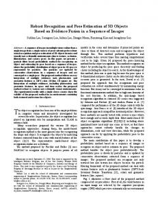
Samples of materials to be tested are examined with a multispectral camera. The used multispectral camera allows imaging in the wavelength range of 450-950nm. Band selections are performed by build in electronically controlled liquid crystal tunable filters (LCTF). Selective band image capture is possible with a bandwidth of 10nm. Illumination of the test specimen is provided by a lighting setup with diffusers with halogen lamps as light sources. Light sources are here halogen lamps. They radiate in a wide visible and infrared spectrum which corresponds with the sensitivity range of the multispectral camera. Optical bandpass filters and a conventional industrial camera can be used for the experiments as well. Some of the defects types on agricultural products show characteristic features in particular wave lengths. Surface defects of a potato tuber can be e.g. imaged with an optimal contrast in the wave length of 530-540nm. Most of the surface defects here are superficial with a depth of approximately 0.3mm. The specimen is illuminated with a custom made LED-lighting setup with 540nm central wave length. The reflected light is received by a grey scale CCD image sensor and interpreted as brightness values. A colour sensor or a multispectral imaging sensor arrangement can be used for special purposes as well. When selecting a customized light source with a particular wave length the spectral sensitivity of camera sensor should be considered (Fig. 3-1).
stereo vision [9] and shape from shading [14]. A possibility to acquire the geometry and intensity information of an object simultaneously using a line scan camera setup is proposed by CALOW [16]. Defects in agricultural products are mentioned by STEVENSON [13]. A classification of cutting methods to correct defects in agricultural products is described in LIGOCKI [10].
3 Approach for defect detection and shape recognition Imaging of the object to inspect can be divided in two main sub tasks – surface imaging and geometry estimation. Principally there are many approaches in the field of optical inspection methods to perform the automated optical inspection systems. According to a given task a suitable combination of methods should be selected. Commonly used approaches have been systemized and evaluated. A summary is depicted in Table 3-1. characteristic feature implementation options camera technology matrix camera line scan camera number of cameras 1 2 3 4 5 … n surface acquisition single image multiple images continuous mode relative movement continuous incremental no movement camera/object movement movement light path between indirect direct plane connica spherica imaging sensor & 2n… object mirror l l mirror mirrors mirrors
lens optics alignment object axis vs. parts feeding
entocentric
telecentric
hypercentric
axial
radial
inclined
linear
circular
free fall
Figure 3-1: Spectral characteristic of a colour camera sensor (left) and a gray scale sensor (right) with overlayed spectrum characteristic of an LED with 540nm centre wave length.
Table 3-1: Morphological analysis – characteristic features of an imaging system for automated inspection
In the field of optical surface inspection improving of contrast between the defective and flawless area of an object plays a major role for reliable and stable automated detection processes. The contrasting is defined especially in terms of lighting and optics. In the field of geometry estimation the shape and dimensions of the object to inspect have to be known in order to describe the location of defect. Finally the defective area can be automatically processed by a machining system.
In general the near infrared band (λ > 800nm) is suitable for visualizing of bigger and sub superficial positioned defects. With increasing weave length superficial defects disappear in images – gross defect are visible only (Fig. 3-2). This effect can be especially useful on agricultural products like apples which have irregular and changing surface colors.
Surface Defects Detection In order to select an optimal method to image the object, different areas of the electromagnetic radiation have to be analyzed. Systematic experiments with different imaging techniques should prove which approach satisfies the requirements.
ISBN: 978-960-474-283-7
Figure 3-2: Surface defects on a potato tuber imaged with 530540nm (left) and 900-910nm (right).
20
Recent Researches in Multimedia Systems, Signal Processing, Robotics, Control and Manufacturing Technology
This property causes difficulties in image registration process.
Due to changing requirements on the inspection task and products to inspect the imaging and lighting systems have to be customized. A mobile image acquisition appliance helps to specify the defects on objects and their characteristic properties. The appliance consists of a multi spectral camera, conventional grey scale camera as well as different types of lightings and optical filters. During the preliminary tests a concept for customised imaging system can be tested under reference conditions. In the following step the optimized imaging system can be configured and assembled.
Stereo Vision The 3D information of an object is here reconstructed from a stereo camera setup and an unstructured light source (passive stereo vision). The geometry reconstruction process is based on disparity of particular image points. Textured surfaces improve the performance and accuracy of this process. Once the surface texture is missing or insufficient an artificial pattern can be projected on the surface (active stereo vision).
Geometry Estimation and Defects Localization Once the visual system for imaging the defects is selected the next task is to localize them geometrically in relation to the world coordinate system. Estimation of the 3D object geometry has to be performed contact-free due to hygienic constrains. For further considerations optical systems based on following principles have been selected and experimentally analyzed: • Photometric stereo (PS) • Time-of-flight camera (TOF) • Triangulation with structured light • Stereo vision (SV)
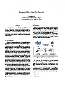
All the mentioned methods for object geometry capturing are capable to image a section of the geometry only. It is caused by the limited field of view from observing point and occlusion effects. In order to obtain a complete object topology the imaging systems have to be extended by more points of view and hence by more cameras. The choosing of imaging systems is a tradeoff among costs, accuracy, robustness, and so on. Practical experiments with selected imaging systems have been performed and evaluated in order to established requirements. The experiments results are represented in a radar diagram in Fig. 3-3.
Photometric Stereo This principle is based on a 3D geometry reconstruction from different lighting conditions using a single camera. In some publications this principle is described as shape from shading (SFS). The reachable depth and lateral resolution is satisfying. But due to natural irregular form, colour and especially brightness deviations of agricultural products, test results were unfavourable. In many cases surface defects cause misinterpretations in depth estimation.
processing speed
supporting defect detection
Time-of-Flight Camera This type of camera uses modulated pulsed infrared light source and reconstructs the depth data from the time-offlight. The image capturing works independent of the object surface colour and brightness but the achievable resolution does not meet the requirements. Current cameras provide a relative low resolution (lateral: 200x200 pixel, depth: app. 10mm).
robustness
costs
accuracy Photometric stereo
Time-of-flight
Stereo vision
Triangulation with structured light
Figure 3-3: Comparison of principles for geometry estimation
Triangulation with Structured Light The geometry estimation is here based on a matrix camera and a line laser module. This technique is similar to the light sheet principle. The achievable lateral and depth resolution is much better than the task requirements. To capture the whole object geometry a relative movement between the camera and object is necessary. A sequence of images is necessary in order to capture the object and reconstruct the object geometry.
ISBN: 978-960-474-283-7
complexity
Implementation Comparison of experiments results lead to a choice for object geometry estimation using stereo vision with auxiliary pattern projection. Additional benefit is the possibility to acquire the geometry as well as the intensity images for surface inspection using the same camera setup. The setup consists finally of four CCD greyscale cameras, laser pattern generators and customized lighting systems (Fig. 3-4).
21
Recent Researches in Multimedia Systems, Signal Processing, Robotics, Control and Manufacturing Technology
approach using k-nearest neighbour has been selected and implemented.
4 Geometric Path Planning The issue of path planning has been studied for more than a few decades. The conventional approach for path planning is the application of the concepts of configuration space (C-Space). In [3], the concept of configuration space and the path planning algorithms are clearly illustrated. The main challenge in path planning is to directly compute Cobc and Cfree, with often a quite high dimensionality of the C-Space [4]. Figure 3-4: Imaging setup for geometry estimation and defects detection
A geometric path planning algorithm proposed by ALJARBOUA [5] will be introduced here. This algorithm has been proved to obviously reduce computation time and find a shortest collision-free path by utilizing the output of the computer vision module and by eliminating any extra work to model the workspace of the robot.
The projected grid pattern allows a significant improvement in performance of stereo images registration especially on sparse textured surfaces. To obtain the object geometry two pairs of stereo camera setups are used for the reconstruction (Fig. 3-5).
4.1 Workspace Representation The 3D geometric path planning algorithm in which the world ࣱ = R3 is based on distance transform where the workspace is modelled as a digital image with a set of occupiable cells as illustrated in Fig. 4.1 Each cell can either be free, occupied by an obstacle or occupied by a point on the path of the robot. Each cell is initialized to zero to indicate a free cell and then the obstacle region φ ⊆ ࣱ is systematically constructed by performing a onetime simple sequential scan of the workspace to assign a non-zero value to all cells occupied by obstacles. The free space Cfree then becomes ࣱ-φ [3].
Figure 3-5: Camera view of a potato with projected grid pattern (left), surface reconstructed with active stereo vision (right).
The LED lighting systems for defects detection are mounted coaxially with cameras. To avoid the negative impact of visible grid pattern on images for surface defects detection a second set of images is needed. During the acquisition of geometry information only the pattern projectors are activated, the lighting system for surface defects is switched off. During acquisition of intensity images the LED lighting system is activated while the laser modules are switched off. While acquiring the second set of images the inspected object usually moves along the conveyor system. Due to a high frame rate of the cameras there is a relatively slight object displacement between both snapshots. It is corrected by an algorithm while matching the position of a surface defect in a 2D image with the 3D object model.
Figure 4-1: The 3D digital image of the workspace with 3D objects. The initial and final positions are notated by Ps and Pf respectively.
Image Processing and Classification Classification of features for defects detection on agricultural products is quite demanding in general. The algorithms have to meet the expectations concerning the flexibility and adaptability. These requirements can be reached by application of learning algorithms. In experiments several approaches have been tested. An
ISBN: 978-960-474-283-7
4.2 Path Planning Algorithm and Improvement In 3D, each cell has 26 adjacent cells, while in 2D each cell has only 8 adjacent cells (see Fig. 4-2). Given the initial and final position of the end-effector, Ps and Pf, the path is computed by recursively re-evaluating the
22
Recent Researches in Multimedia Systems, Signal Processing, Robotics, Control and Manufacturing Technology
processing movable objects which is transported by a conveyor belt.
distance to the final goal from each of the neighbouring cells to select the next intermediate cell that lies on the path.
Figure 4-4 illustrates the industrial application of geometric path planning algorithm. (a) End-effector is set to wait in the front of workspace, if there unprocessed objects does not exist. (b) End-effector begins to move to an unprocessed object, if the unprocessed object containing defects appears in workspace. (c) After processing end-effector moves to next unprocessed object.
Figure 4-2: In 2D, each cell has 8 adjacent cells. In 3D, each cells has 26 adjacent cells. [3]
while ( distance ≤ ε): for i = 1 → 26: dist(i) = ∞ if (cell(i) is free & !=history) dist(i)=norm( cell(i)- Pf ) [distance I] = min(dist) new cell = cel(I) At each iteration, the Euclidean distance from all the 8 adjacent cells to the final position is initialized to infinity and then reassigned the actual distance if the cell is not occupied by an obstacle and it is not already part of the path. Finally, the cell with the shortest distance from the goal is selected and added to the path. This process is repeated until the distance from the goal is less than the specified tolerance ε [3].
Figure 4-4: Application on movable objects. Red spot: Position of end-effector; Blue spot: processed object; Black spot: unprocessed object
5 Realization and Implementation
Some readers might argue that it is impossible to reach the goal position by utilizing the algorithm above; due to the goal position itself lies on the surface of obstacles (review Figure 4-1). Therefore, one improvement has to be done. In section 3, the coordinate of defect point detected by camera system should be offset from the surface of 3D objects. Now, the algorithm can be employed in our paper. The shortest collision-free path is illustrated in Fig. 4-3.
The definition of specific problem has to be considered for the conceptualization of processing and machine design. In addition to the geometry of objects and characteristic of defects, the processing speed and accuracy also have to be considered. For flat products a two axes portal frame might be sufficient. Objects with a more complex geometry need a machine design with an appropriately increased number of degrees of freedom.
(a) (b) Figure 4-3: (a) Defect point is offseted from surface. (b) Optimal path connecting the initial and goal position
Figure 5-1: Test facility for water jet cutting
Corresponding to different inspected goods there are different method for processing. For example, water jet cutting is particularly suitable for food processing and a flexible and fast processing method. Fig. 5-1 shows the test facility for water jet cutting.
4.3 Application on Movable Objects The geometric path planning algorithm has been proved to be efficient in real-time path planning, which can be incorporated in robot system with on-board sensors. This is quite important for industrial application on ISBN: 978-960-474-283-7
23
Recent Researches in Multimedia Systems, Signal Processing, Robotics, Control and Manufacturing Technology
[11] Lu, Renfu; Park, Bosoon: Hyperspectral and multispectral imaging for food quality and safety, In: Sensing and Instrumentation for Food Quality and Safety, Jg. 2, PP. 131-132, 2008. [12] Scarpin, D.; Wahrburg, J.: Entwicklung eines robotergeführten Lichtschnittsensors für die berührungslose Erfassung anatomischer Strukturen. In: Burgert, O.; Lüder, A. K.; Preim, B; Schipper, J. (Hrsg.) 9. Jahrestagung der Deutschen Gesellschaft für Computer- und Roboterassistierte Chirurgie e.V., DAV Verlag PP. 231-235, 2010. [13] Stevenson, Walter R.: Compendium of Potato Diseases. 2. ed., 3. printing. St. Paul, Minn.: APS Press (The disease compendium series of the American Phytopathological Society), 2009. [14] Zhang, Ruo; Tsai, Ping-Sing; Cryer, James Edwin; Shah, Mubarak: Shape from Shading: A Survey. In: IEEE Transactions on Pattern Analysis and Machine Intelligence, Jg. 21, PP. 690-706, 1999. [15] Weyrich, Michael; Klein, Philipp; Laurowski, Martin: Optische Lokalisierung, Klassifizierung und automatische Behebung von Fehlern am Beispiel von Agrarprodukten; in Forum Bildverarbeitung 2010. KIT Scientific Publishing, 2010, PP. 389-400. [16] Calow, Roman: Schnelles Zeilensensorsystem zur gleichzeitigen Erfassung von Farbe und 3D-Form; in Forum Bildverarbeitung 2010. KIT Scientific Publishing, 2010, PP. 181-192. [17] Michelsburg, M.; Gruna, R.; Vieth, K.-U.; Puente Léon, F.: Spektrale Bandselektion beim Entwurf automatischer Sortieranlagen; in Forum Bildverarbeitung 2010. KIT Scientific Publishing, 2010, PP. 389-400.
6 Conclusion In this paper approaches for defect detection and geometry estimation were discussed. Based on these approaches an algorithm and application for path planning also were presented. The effort of comparing a set of computer vision methods has been done. As a result the choosing of a suitable principle for defects detection and shape recognition will be facilitated according to the radio diagram. Specific processing of defects for example on agricultural objects helps to reduce the waste. For this surface defects detection and geometry estimation have to be combined to deduce the processing method and the path planning. Application of the presented methodology depends on the specific problem definition. Vision guided applications could be conceptualized by this universal methodology.
References: [1] Niola, V.; Rossi, C.; Savino, S.; Strano, S.: Robot Trajectory Planning by Points and Tangents; in Proceedings of the 10th WSEAS Int. Conference on ROCOM; WSEAS Press, 2010. [2] Zhang, Y.; Wang, J.: Obstacle Avoidance for Kinematically Redundant Manipulators Using a Dual Neural Network; in Proceedings of the 8th WSEAS Int. Conference on ROCOM; WSEAS Press, 2008. [3] Steven M. LaValle. “Planning Algorithms”. Cambridge University Press. 2006. [4] B. Siciliano, O. Khatib. Springer Handbook of Robotics, 2008. [5] Ziyad Aljarboua. Geometric Path Planning for General Robot Manipulators. WCECS 2009. [6] Besl, P.: Active Optical Range Imaging Sensors. In: Machine Vision and Applications: Springer, Bd. 1, 1998. PP. 127-152. [7] Brosnan, Tadhg; Sun, Da-Wen: Inspection and grading of agricultural and food products by computer vision systems a review. In: Computers and Electronics in Agriculture, Jg. 36, H. 2-3, PP. 193-213, 2002. [8] Kissing, Olaf: Ein Beitrag zur Gestaltung einer lernfähigen Klassifikation in der automatischen Oberflächeninspektion. Diss. Universität Siegen, Shaker, Aachen 2010. [9] Lazaros, Nalpantidis; Sirakoulis, Georgios Christou; Gasteratos, Antonios: Review of Stereo Vision Algorithms: From Software to Hardware. In: International Journal of Optomechatronics, Jg. 2, H. 4, PP. 435-462, 2008. [10] Ligocki, Andreas: Schneiden landwirtschaftlicher Güter mit Hochdruckwasserstrahl. Techn. Univ., Diss.--Braunschweig, Aachen: Shaker, 2005. ISBN: 978-960-474-283-7
24