Vision Based Target Tracking and Collision Avoidance for Mobile Robots A. Tsalatsanis, K. Valavanis1, A. Yalcin Department of Industrial & Management Systems Engineering University of South Florida, Tampa, FL 33620 Tel: (813) 974-6564, Fax: (813) 974-5456 E-mail:
[email protected],
[email protected],
[email protected] 1 Department of Computer Science and Engineering Abstract- A
real-time object tracking and collision avoidance method for mobile robot navigation is presented using stereo vision and a laser sensor. Stereo vision is used to identify the target while laser based range measurements are utilized to avoid collision with surrounding objects. The target is tracked by its predetermined or dynamically defined color. Experimental results in indoor environments demonstrate the effectiveness of the method. Keywords-Moving target tracking; mobile robot navigation;
1
Introduction
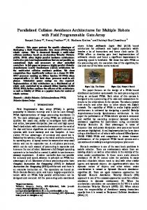
A robust and efficient method is presented for mobile robot dynamic target tracking and collision avoidance in indoor environments using stereo vision and a laser range finder. Key characteristics of the tracking system are realtime operation, efficient computational complexity and ability to adapt to different environments and moving targets. The computational complexity of the vision based tracking is O(n2), where n is the dimension of a square image; the complexity of the laser based range measurement is O(m), where m is the number of laser segments. Contrary to most existing approaches that are restricted to specific environments and certain types of targets such as templates [1, 7, 15], cars [2, 9] and humans [4, 6, 12, 21], the presented method is rather general and applicable to any indoors environment. The target is identified by its color using the HSI color space and a region growing algorithm. The target color may be either predetermined or dynamically defined, regardless of the target’s shape or other physical characteristics. Future work involves distance computation between the target and the robot using the stereo vision system. Thus, limitations have been imposed on the cameras’ motion so that pixels correspondences are found across a single epipolar line reducing in this way the computational complexity of the task. Distance will be used to control the mobile robot’s velocity. Collision avoidance with objects other than the target is accomplished using data from the laser range finder. The proposed tracking system operates as follows: As soon as a potential target has been identified, both cameras
track the target independently of each other with their pan/tilt mechanisms. The robot’s steering angle, φ, is controlled by the angle of the pan mechanism as illustrated in Figure 1. Thus, the target is tracked even if one of the cameras fails to identify it; moreover, in this way, the target is being tracked even while the mobile robot avoids collision with surrounding obstacles, or the target moves in uneven terrains. Experimental validation and verification of the proposed method is demonstrated using the ATRV-Jr skid steering differential drive robot, equipped with 3 GHz P IV processor and 1 GB of RAM. The ATRV-Jr uses a 30m range laser finder that is located in front of the robot, a GPS, a compass unit and a stereo vision system that consists of two uncalibrated pan/tilt video cameras, SONY EVI-D30, mounted on top of the robot at a distance of 35 cm from each other. The robot runs RedHat Linux 7.0 and Mobility interface. Target
X
φ
Left Camera Steering direction
Right Camera
φ
Y
Robot
Figure 1. Tracking control system
Suitable applications that the method may be used are warehouse patrolling and office building security and inspection, where the target may be any moving object and / or human (friend or enemy). However, the proposed method will be used as a failure recovery mechanism in a warehouse / parking lot patrolling application using a team of mobile robots in a master / slave configuration. When the navigation sensors (GPS, IMU and odometer) of a robot fail, then using its vision system it will be able to follow any other robot of the team to complete its task.
The paper is organized as follows: The rest of this Section refers to related work and comparisons. Section II describes the vision system algorithm while Section III presents the motion algorithm. Section IV is dedicated to experimental results and Section V concludes the paper.
1.1
Related work and comparisons
Reported research in [1] uses template matching techniques for object tracking. The authors use a rated gyro and a camera to solve the problem of image deformation caused by the camera rolling and pitching during the mobile robot’s motion on irregular terrains. In [2], a visual feedback controller is proposed using a fixed camera to control the mobile robot to track a moving target. The target is predetermined and its dimensions are known. In [3] and [4] the Condensation Algorithm has been used to implement vision based tracking of moving objects. Objects are tracked by their outlines and features. Research in [5] solves the problem of target tracking and collision avoidance using magnetic sensors mounted on the left and right of the robot. A multi-modal anchoring method has been used in [6] to track humans with a vision system and a laser range finder. Laser data are used to extract the legs of a person while the skin color is detected through camera images. In [7] a vision based tracking system is presented that uses trinocular sets of precisely aligned and rectified images to represent the trajectory of the object being tracked. In [8] a target tracking controller has been designed with collision avoidance consideration and simulation results are shown. In [9, 10] an experimental study has been performed on tracking two autonomous mobile robots using only distance sensors. Research in [11] derives a heuristic algorithm to match the velocity of target and tracker in an indoor structured environment. In [12] a person tracking approach is presented using a stereo vision and face detection modules. This system identifies skin color using a converted RGB color space and performs face detection using the face detector library reported in [16]. Reported research in [13] uses infrared sensor to design a fuzzy controller to track a mobile robot. In [14] a fuzzy controller is presented for a general target tracking system. Finally, research in [15] uses template matching techniques for visual target tracking. In [17], a fuzzy algorithm is used to detect an object based on a color cue and tracking is based on a maximum radius of displacement in subsequent frames. Concerning vision based techniques, research in [20] uses multivariate decision trees for piecewise linear nonparametric function approximation to learn the color of the target object from training samples. The approach in [21] proposes a color model which includes the intensity information in HSI color space using B-spline curves for face tracking. Research in [22] uses the Histogram Intersection and Histogram Back-projection techniques to match and locate a color in an image scene. In [23] color segmentation is performed based on contrast information and adaptive thresholds in static images. The authors in [24] use color segmentation to identify obstacles in indoor
environments. Using a training set of images and the r-g color space they present a model robust to shadows and illumination changes. Similar to [22], researchers in [25] propose color indexing using histograms of RBG color ratios. Another color tracking algorithm is presented in [26] where a neural network is used to robustly identify skin color regardless of lighting conditions. In [27] color histogram information is used to detect and track pedestrian for a stationary visual surveillance system. The main differences and advantages of the presented approach compared to the presented related research are: • Using color histograms on the H-I plane allows for a variety of objects to be used as a target, independently of the target’s shape, size or other physical characteristics. • Both cameras of the vision system track a target independently, providing a redundant mechanism that helps avoiding loosing the target. This means that even if one camera ‘looses the target’, it can retrieve information from the other camera to find it again. • The robot’s direction is controlled by the pan/tilt angles of the cameras, allowing the robot to avoid obstacles and keep tracking a target, or to keep tracking a target that moves on uneven terrains.
2 Vision System The vision system of the ATRV-Jr consists of two uncalibrated pan/tilt color cameras mounted on top of the robot at a distance of 35 cm from each other. The main steps of the proposed vision based tracking algorithm to convert image information to camera’s motion are shown in Figure 2. Each step is presented separately. Camera 1
Camera 2
Image acquisition
Image acquisition
Color Space Transformation
Color Space Transformation
Target Selection
Target Selection
Move Camera to Track the Target
Move Camera to Track the Target
Extraction of interesting points
Extraction of interesting points
Interesting Points Correspondence Distance computation
Figure 2. Block diagram of the vision system function
2.1
Image Acquisition
Image acquisition is achieved by using the Video4Linux API at a rate of 30 fps. Both cameras share the same frame grabbing device, Spectra 8, which supports rates up to 30 fps from 4 analog video inputs. Each 24 bit color image has a resolution of 320x240 pixels.
2.2
Target Selection
The target is being tracked by its color that can be either predetermined or dynamically defined in the image scene. Identifying color in an image using a region growing technique instead of template matching or pattern recognition techniques requires less computational time and allows the system to be robust in choosing multiple targets. The HSI color space has been chosen for the image manipulation techniques discussed below. This is because the HIS color space is similar to the human perception of colors [28].
2.2.1
Predetermined color
When the target is a known object, the variation of the hue, saturation and intensity values of the color’s representation in the HSI color space is known. A segmentation technique on H-I plane based on a region growing algorithm is used to separate the target from the image’s background. The basic concept is to identify a pixel, “seed”, in the image that takes the mean hue and intensity values within the area of the object’s color and grow a region with similar neighboring pixels. For example, the T-shirt in Figure 3a has hue and intensity values that vary between (310, 340) and (125, 145), respectively. Thus, the seed pixel will have a hue value of 325 and an intensity value of 135. The region growing algorithm will merge neighboring to the seed pixels that have hue and intensity values in the former area. Figure 3b shows the result of this technique.
(a)
(b)
zero and it is 4-connected, then motion has been detected. Initially, the original color images were used for the subtraction, but since the variations of color components are significant even for images taken within short periods, it has been decided that the subtraction will occur in the grayscale images. The time difference between two frames must be proportional to the target’s speed to identify the motion in the images. If the target is moving too fast and the time difference between the two frames is large, then the system will fail to identify motion. Reversely, if the target is moving slow and the time difference between the two frames is small, the threshold of 2% of the image pixels will not be met. Experimentally it has been determined that for a walking man or for a moving mobile robot a difference of 0.3sec is adequate to identify motion between the two frames. A median filter with window size 5x5 is applied to the subtracted image to eliminate individual pixels that were erroneously recognized as ‘motion’. These pixels usually belong to objects with shining surfaces where light is irregularly reflected. When the target has been detected, the RGB to HSI transform is performed to the region of the image that surrounds it. This region will be denoted from now on as region of interest. To identify the color of the moving object, the histograms of the hue and intensity components are computed for the region of interest. The hue and intensity value with the greater frequency in the region of interest is used as the seed value for the region growing algorithm. To improve the accuracy of this selection, the seed is the pixel where its 8-connected neighbors present the maximum hue and intensity values in the region of interest. This is a grueling criterion for the selection of the seed that helps to avoid locating objects in the scene with similar colors. Then, the region growing algorithm is applied to merge pixels that present hue and intensity values in the range of ± 20 of the seed’s values. In Figure 4 two sequential images (a), (b) are depicted as well as the region of interest derived by the motion (c) and the region growing algorithm (d).
(a)
(b)
(c)
(d)
Figure 3. Region growing results for the segmentation of an object with known color
2.2.2
Dynamically determined color
When the target is unknown, it is defined as the first moving object in the image scene. Motion in a scene is identified by subtracting sequential frames. If the outcome of the subtraction is a black image then no motion has been detected in the image scene. On the other hand, if 2% or more of the outcome image pixels has values different than
Figure 4. Region growing results for the segmentation of an object with unknown color
The hue and intensity component histograms are only computed for the initial pair of images and the maximum values are used to run the region growing algorithm for the rest of the images. Since illumination may vary even in indoor environments the maximum values of the Hue and Intensity components are recalculated for the region of interest in the case that the seed cannot be found.
2.3
respect to the robot’s direction, Figure 6b. In the first case the failed camera will be forced to the opposite angle of the second camera and in the second case the failed camera will be forced to the angle of the second camera. Given the robot’s velocity and the camera’s angle on the horizontal axis, the steering velocity of the robot can be computed by:
| y |= | x | tan φ
Target tracking
One of the differences of the proposed method compared to others is that in existing approaches there is an effort to control the tracker’s speed and steering angle to follow the target holding the vision system fixed. In the presented method, each camera of the stereo vision system tracks the target using their pan/tilt mechanisms. Thus, the target is being tracked even when the robot is in collision avoidance mode, or when the target is moving in irregular terrains. The robot’s steering angle, φ, is controlled by the angle of the pan mechanism of the cameras, Figure 1. Each camera’s motion is such that it keeps the target at the center of the image. Therefore, each image is segmented into 14 regions as shown in Figure 5. When the mass center of the pixels belonging to the target falls into a numbered sub image, an appropriate motion of the pan/tilt mechanism tends to reinstate the target to the center of the image. Experimentally it has been determined that when the mass center resides to the sub images 1-8, an angle of approximately 7o on the horizontal axis and 5.4o on the vertical axis is efficient to reinstate the target to the center of the image. When the mass center resides on the sub images 9-14 a sharper motion is required, thus the angle of the horizontal axis is set to 12o.
(1)
where y is the steering velocity, x is the robot’s velocity and φ is the horizontal angle of the camera. Target
Target
Optical axis Optical axis
X
Left Camera
Optical axis
Optical axis
Right Camera
Y
X Left Camera
Right Camera
Y Robot
Robot
a
b
Figure 6. Location of the target related with the robot
3 Computational time The computational time required to identify the target depends heavily on the part of the image that the target covers. The maximum frame rate reaches the 20 fps. This is an adequate frame rate when the target is a walking man or a mobile robot, considering that the maximum velocity of the tracker cannot exceed the 1 m/s.
4 Motion Algorithm
Figure 5. Image segmentation for camera motion
Since stereo correspondences will be needed to calculate the distance between the robot and the target, both cameras are forced to the same angle in the vertical axis (tilt). This allows calculating pixel correspondences across a single epipolar line instead of the whole images, reducing the required computational time. The case of one camera failing to locate the target is also considered; then, data derived and collected from the failed camera may no longer be useful. Two cases have been considered. First, the target is located in front of the robot Figure 6a, and second the target is located on an angle with
The laser range finder is divided into three regions; each one is responsible for collision detection in the three main directions: front, right and left. All these inputs are fed to the motion algorithm which decides for the vehicle’s rotational and translational speed. The assumption is that the robot stays still until the vision system detects a target. This is a valid assumption since a failed robot will remain in its current location until it receives new commands from a supervisory controller, or a patrolling robot will visually inspect its territory until a motion is detected. As soon as the target has been identified, the robot starts moving towards it. Given the robot’s velocity and the camera’s angle on the horizontal axis, the steering velocity of the robot is obtained using (1). Collision possibilities are computed using the data derived from the laser range finder in the three main
directions, front, right and left of the robot, as shown in Figure 7. The safety distance from the robot has been arbitrarily set to 40 cm. When an obstacle is detected at a distance less than this threshold; a correction in the steering angle of the robot is performed driving it away from the obstacle. At the same time both cameras keep tracking the target regardless of the robot’s motion. When the vehicle passes the obstacle, it resumes its past route according to the cameras’ pan positions. The system stops the robot when the vision system looses the target.
distinguish the target from the background, even if objects with similar colors appear in the image scene. Figure 8 demonstrates the ability of the vision system to detect the target wearing blue pants. The robot in this sequence is not moving. Notice that both shirt and pants are of blue color.
Figure 7. Segmentation of the laser finder beam in three regions
The correction in the steering angle forces the robot to keep a distance greater than 40 cm from the obstacle, while the velocity of the robot reduces to half. This is performed using a simple set of rules: 1. If an obstacle is detected in the right side of the robot, turn left until its distance is greater than 40cm. Then carry on the target’s route. 2. If an obstacle is detected in the left side of the robot, turn right until its distance is greater than 40cm. Then carry on the target’s route. 3. If an obstacle is detected both in the left and the right side of the robot and the projections on the y axis (Figure 10) of both distances are greater than 20cm, which is the distance between the center of the laser range finder and the edges of the robot, then continue straight passing through the obstacles. Otherwise, conventionally, turn right until the distance computed by the left segment of the laser is greater than 40cm. 4. If an obstacle is detected in front of the robot, it is unlikely that this object is the target since the robot would have stopped moving, turn right until the distance computed by the left segment of the laser is greater than 40cm.
5
Results
Experiments have been conducted in an indoor lab environment with several “furniture obstacles” of different shapes, sizes and colors. For implementation purposes a person wearing different color clothes is used as the target. In the frames that follow, one can note the difference in lighting conditions, as well as the ability of the algorithm to
Figure 8. Tracking Blue Color
Figure 9 demonstrates the same procedure but this time a red color is chased. Notice that the red cones on the background do not confuse the algorithm.
Figure 9. Tracking Red Color
Figure 10 presents the robot’s view as it follows a person in a corridor. Notice the cameras’ motion and the turn of the robot at the end of the corridor.
Figure 11. Tracking red color and obstacle avoidance
Figure 12. Tracking blue color and obstacle avoidance
Archived videos of the experiments are available at www.eng.usf.edu/~atsalats
6 Conclusions and future work
Figure 10. Tracking red color
Figures 11 and 12 demonstrate tracking and obstacle avoidance from an external video source.
This paper has presented a vision based target tracking method for mobile robots using a stereoscopic vision system and a laser range finder. Experimental results demonstrate the effectiveness and the robustness of the approach. Significant advantages over the other vision based target tracking techniques concern the ability on tracking a variety of objects and that the robot’s motion derives from the horizontal angle of the cameras, which allows the robot to avoid obstacles and keep tracking a target, or to keep tracking a target that moves on irregular terrains. The presented approach is initialized using motion estimation techniques to specify the target and compute the color histograms. In the presented results the target is the only object moving in the image scene. However, if more than one object is moving, the algorithm can be trained for the one that occupy greater portion of the image.
Alternative methods to avoid the randomness of the motion estimation can be used. Methods such as template matching will specify with accuracy the object that needs to be tracked. This is only for initialization purposes. When the object of interest is located in the image, its color histograms are computed and the rest of the algorithm continues as is. Future work involves distance measurements between the robot and the target using the stereo vision system. This will allow the robot to adjust its velocity according to the target’s distance. Acknowledgement: This research is partially supported by an ARO Grant with award number W911NF-06-1-0069.
7 [1]
[2]
[3]
[4]
[5]
[6]
[7]
[8]
[9]
[10]
[11]
[12]
[13]
[14]
[15]
References J. Ding, H. Kondou, H. Kimura, Y. Hada, K. Takase, “Robust Tracking for Camera Control on an Irregular Terrain Vehicle”, in Proceedings of the 41st SICE Annual Conference, Volume 2, pp. 1191 – 1196, 2002. H.Y. Wang, S. Itani, T. Fukao, N. Adachi, “ImageBased Visual Adaptive Tracking Control of Nonholonomic Mobile Robots”, in Proc. of IEEE ICIRS, Hawaii, pp. , Nov.2001. E. B. Meier, F. Ade, “Using the Condensation Algorithm to Implement Tracking for Mobile Robots”, in Third European Workshop on Advanced Mobile Robots, pp. 73-80, 1999. H.M. Gross, H.J. Boehme, T. Wilhelm, “A Contribution to Vision Based Localization, Tracking and Navigation Methods for an Interactive Mobile Service Robot”, in 2001 IEEE Intern. Conference on Systems, Man and Cybernetics, pp. 672-677, 2001. J. Miyata, T. Murakami, K. Ohnishi, “An Approach to Tracking Motion of Mobile Robot for Moving Object”, in 26th Annual Confjerence of the IEEE Industrial Electronics Society, vol. 4, pp. 2249 – 2254, 2000. M. Kleinehagenbrock, S. Lang, J. Fritsch, F. Lomker, G.A. Fink, G. Sagerer, “Person Tracking with a Mobile Robot based on Multi-Modal Anchoring”, in Proceedings of 11th IEEE International Workshop on Robot and Human Interactive Communication, pp. 423-429, 2002. P. Saeedi, P. Lawrence, D. Lowe, “3D Motion Tracking of a Mobile Robot in a Natural Environment’, in Proc. Of IEEE International Conference on Robotics and Automation, Volume 2, pp. 1682 – 1687, 2000. S.O. Lee, Y.J. Cho, M.H. Bo, B.J. You, S.R. Oh, “A Stable Target Tracking Control for Unicycle Mobile Robots”, in Proceedings of International Conference on Intelligent Robots and Systems, vol. 3, pp. 18221827, 2000. F.C. Lin, W. Tong, T.H.S. Li, “An Experimental Study on Tracking Control of Two Autonomous Mobile Robots”, in 23rd International Conference on Industrial Electronics, Control and Instrumentation, vol.3, pp. 1311-1316, 1997 W. Tong, T.H.S. Li, “Realization of Two-Dimensional Target Tracking Problem via Autonomous Mobile Robots Using Fuzzy Sliding Mode Control”, in Industrial Electronics Society, Volume 2, pp. 1158 – 1163, 1998.
[16]
[17]
[18] [19] [20]
[21]
[22]
[23]
[24]
[25]
[26]
[27]
[28]
Z. Lin, V. Zeman, R.V. Patel, “On Line Robot Trajectory Planning for Catching a Moving Object”, in IEEE International Conference on Robotics and Automation, vol.3, pp. 1726-1731, 1989. T. Darrell, G. Gordon, M. Harville, J. Woodfill, “Integrated Person Tracking Using Stereo, Color and Pattern Detection”, in Proccedings of Computer Vision and Pattern Recognition, pp. 601- 608, 1998. T.H.S. Li, S.J. Chang, W. Tong, “Fuzzy Target Tracking Control of Autonomous Mobile Robots by using Infrared Sensors”, in IEEE Transactions on Fuzzy Systems, Vol.12, Issue 4, pp. 491-501, 2004. R.C. Luo, T.M. Chean, “Autonomous Mobile Target Tracking System Based on Gray-Fuzzy Control Algorithm”, in IEEE Transactions on Industrial Electronics, Vol. 47, Issue 4, pp. 920-931, 2000. C. Balkenius, L. Kopp, “Visual Tracking and Target Selection for Mobile Robots”, in Proceedings of the First Euromicro Workshop on Advanced Mobile Robot, pp. 166 – 171, 1996. H. Rowley, S. Baluja, T. Kanade, “Neural Network Based Face Detection”, in Proc. IEEE Conf. Computer Vision and Pattern Recognition, pp. 690-696, IEEE Computer Society Press, 1997. Montecillo-Puente F.J., Ayala-Ramirez V., PerezGarcia A., Sanchez-Yanez R.E., “Fuzzy color tracking for robotic tasks”, in IEEE International Conference on Systems, Man and Cybernetics, Vol. 3, pp. 2769 – 2773, 2003. R. Jain, R. Kasturi, B.G. Schunck, Machine Vision. McGraw-Hill International Editions, 1995. John C. Russ, The Image Processing Handbood. IEEE PRESS, 1995. S. Buluswar, B. Draper, “Color machine vision for autonomous vehicles”, in Engineering Applications of Artificial Intelligence, vol. 11, pp. 245-256, 1998. Y.B. Lee, B.J. You, S.W. Lee, “A Real time Color Based Object Tracking robust to Irregular Illumination Variations”, in Proc. Of IEEE International Conference on Robotics and Automation, pp. 1659-1664, 2001. M. Swain, D. Ballard, “Indexing Via Color Histograms”, in Proc. Of the Third International Conf. on Computer Vision, pp. 390-393, 1990 H.C. Chen, W.J. Chien, S.J.Wang, “Contrast Based Color Segmentation With Adaptive Thresholds”, in International Conf. on Image Processing, vol. 2, pp. II73-II-76, 2002. Y.Chao, Z. Changan, “Obstacle Detection Using Adaptive Color Segmentation and Planar Projection Stereopsis for Mobile Robots”, in Proc. Of IEEE International Conf. on Robotics, Intelligent Systems and Signal Processing, pp. 1097- 1101, 2003. B.V. Frunt, G.D. Finlayson, “Color Constant Color Indexing”, in IEEE Transactions on Pattern Analysis and Machine Intelligence, vol. 17, No.5, pp. 522-529, 1995. Ying Wu, Huang T.S., “Nonstationary color tracking for vision-based human-computer interaction”, in IEEE Transactions on Neural Networks, Volume 13, Issue 4, pp. 948 – 960, 2002. Orwell J., “Remagnino P., Jones G.A.,Multi-camera colour tracking”, in Second IEEE Workshop on Visual Surveillance, pp.14 – 21,1999. K. Sobottka, I. Pitas, “Segmentation and Tracking of Faces in Color Images”, in Proc. of Automatic Face and Gesture Recognition, pp. 236-241, 1996.