Visual Programming for Hybrid User Interfaces Christian Pirchheim∗
Dieter Schmalstieg†
Alexander Bornik‡
Graz University of Technology
A BSTRACT This paper presents a novel software system called Thekla that facilitates the integration of 2D and 3D user interfaces into hybrid, distributed mixed reality applications. Combining heterogenous display and interaction devices allows mixing and matching of interaction styles for a convenient user experience that is often absent from pure virtual reality applications. To this aim, Thekla enables an application developer to include standard 2D user interface components based on the popular Qt framework with a convenient visual programming environment, thereby significantly easing the introduction of 2D components into hybrid user interfaces, compared to the effort typically necessary in previous virtual and mixed reality frameworks. Thekla consists of a 2D component which synchronizes Qt-based user interfaces with 3D scene graphs, and a 3D component which translates 3D tracker input into 2D events consumable by desktop applications, allowing to turn any screen or surface into a touch screen. The rapid prototyping of 2D user interfaces is supported by Qt Designer, a professional visual programming tool bundled with Qt. Overall, Thekla provides the necessary software components for the seamless integration of distributed hybrid 2D-3D user interfaces. Several examples including a complex surgery planning application demonstrate Thekla’s abilities. Index Terms: C.2.4 [Computer Communication Networks]: Distributed Systems—Client/server H.5.1 [Information Interfaces and Presentation]: Multimedia Information Systems—Artificial, augmented, and virtual realities 1
I NTRODUCTION
The appeal of Virtual Reality (VR) user interfaces lies in the ability to let a user directly and naturally manipulate three-dimensional content. However, real-world applications do not only require 3D object manipulation, but also involve other tasks, often summarized as system control. Bowman et al. [3] give the following definition: “System control is the action in which a command is issued to either change the mode of interaction or the system state.” System control is well understood in conventional desktop graphical user interfaces (GUI), but often poorly supported and needlessly complicated in VR systems – for example, consider the notorious flying menus which must be operated with cumbersome 3D ray picking. Mixed reality (MR) has the potential to address the need for proper system control by combining virtual 3D content with real-world interfaces, where one possibility is that the real world interfaces have the shape of tried-and-tested 2D desktop interfaces. This approach leverages some ideas from the field of ubiquitous computing and has been dubbed hybrid interface by Feiner and Shamash [7]. Hybrid user interfaces have been introduced a while ago, but have met only limited success in practical VR applications. We believe this is not so much a user interface design but a software ∗ e-mail:
[email protected] [email protected] ‡ e-mail:
[email protected] † e-mail:
engineering problem, grounded in a lack of proper development tools for the 2D part of the interface. While developers of desktop applications can rely on visual programming tools which make the integration of a 2D GUI quick and painless, experimental VR and MR systems do not offer similar commodities. A common practice for desktop VR applications is to split the screen between a 3D window and a 2D panel. However, as soon as the VR/MR application is required to be distributed across multiple hosts, such as in a CAVE or shared space MR environment, standard GUI toolkits are no longer trivially integrated because they lack suitable networking capabilities. Instead, system control is usually deferred to rudimentary system control toolkits directly embedded in the VR system, or attached on a per-application basis with proprietary code. These contingencies lack in code resusability, ergononomics and are not supported by visual programming tools. Thekla is novel software approach that aims to overcome these deficiencies. It extends the MR framework Studierstube [18] with the necessary components for the rapid prototyping of hybrid user interfaces. Studierstube is based on a number of mature components which form the foundation for our hybrid user interface approach: The scene graph library Coin3D1 , based on [19] provides 3D graphics. OpenTracker [14] manages input and tracking devices. Muddleware [22] is a blackboard communication tool for light-weight application synchronisation within Studierstube. We further chose Qt and Qt designer as mature tools for cross-platform GUI development. Thekla, the solution described in this paper, can be characterized as the “glue” that integrates the 2D and 3D components into a seamless hybrid user interface with minimal demands on the side of the application developer. Our intent was to make it so easy to integrate a 2D part into a hybrid environment that there is no reason not to do it. In this way we hoped to encourage more sophisticated and feature-rich yet easy to use MR applications. The quick adoption of Thekla in the ongoing research projects in our lab seems to confirm this expectation. As the main contribution of Thekla we see the fact that it goes beyond the proof of concept stage to show that the integration of professional development tools and experimental MR software is feasible and useful. Thekla is not limited to a particular set of tools, but can be easily extended for example with other 3D libraries. 2
R ELATED W ORK
Thekla is a system integration effort and draws inspiration from a variety of areas, such as message passing systems, computersupported collaborative work technology and visual programming. For reasons of brevity, we limit ourselves only to VR and MR user interface approaches that are relevant in the context of Thekla. A major inspiration are hybrid user interfaces that integrate multiple heterogeneous user interface components according to a ubiquitous computing manner. Besides the EMMIE system [5], there are several works by Rekimoto which aim at bridging physical spaces and incorporate multiple computers and input devices, for example pick-and-drop [15] and Augmented Surfaces [16]. The idea of incorporating 2D user interfaces into VR and MR environments through the use of pen-and-tablet interfaces, goes back 1 http://www.coin3d.org
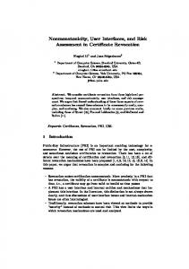
(a) Shared system state of 2D and 3D applications is synchronized by Thekla’s 2D component.
(b) Thekla’s 3D component enables tracked input devices to act as desktop mouse substitutes. Figure 1: Thekla’s components are embedded in 2D Qt and 3D Studierstube/Coin applications and provide synchronization and integration features supporting the authoring of hybrid user interfaces.
to the idea of displaying legacy 2D content in [1]. Later works used 3D rendering in MR to display proprietary 2D user interfaces [20, 17, 6]. Many VR and MR architectures are based on communicating heterogeneous components. Recent examples include DWARF [11], AMIRE [23] and MORGAN [4]. These approaches typically involve the use of object brokers such as CORBA and involve a peer to peer message passing style, which has different advantages and disadvantages to blackboard approaches such as the one featured in Muddleware. By wrapping Qt as one of the components, these systems are able to achieve a similar hybrid user interface, but the necessity of CORBA to publish interfaces in advance does not lend itself to rapid prototyping intermixed with visual programming to the same degree as supported in Thekla. Likewise, many distributed VR systems utilize a shared scene graph, for example Avango [21] and DIVE [8], but scene graph sharing does not address any 2D GUI aspects at all. Several authors have investigated aspects of authoring MR environments. For example, [23] describes a visual editor to define the architecture of MR applications and [9] presents a tool for the layout of the 3D aspects of MR applications. However, these approaches do not address system control or 2D user interfaces and our work is complementary to these approaches.
should be coordinated, maybe even changing the set of components at runtime - there can be multiple concurrent GUIs and scene graphs. We therefore decided to model system state explicitely and store it in a central repository, Muddleware. A subset of the application state is the state of the graphical objects in the scene graph, such as color or position. Input events of the user are not directly distributed, but rather affect some portion of the overall system state, and these state changes are distributed. Muddleware provides persistence of the system state as well as a known point of entry into the system, so all other components may be dynamically altered or even restart after failure. Muddleware supports a publish-subscribe architecture, so components can subscribe to certain aspects of the system state and receive updates irrespective of which component made them. A component joining an ongoing session can receive a complete copy of the relevant state from Muddleware. This is easily possible since Muddleware supports a hierarchal data model that allows to refer to a set of data items with a single root pointer. Thekla’s 2D component allows to create 2D GUIs to control a certain aspect of the system and synchronize the results with other components, notably a 3D scene graph, irrespective of the location of the scene graph component (see Figure 1(a)). In particular, Thekla allows to remote control a scene graph from a different host. Multi-user operation is implicit since multiple scene graph components and multiple GUIs can co-exist and can be arbitrarily wired together to form collaborative software ensembles. The synchronisation between two components sharing a piece of system state works in both directions, so that 2D user interfaces are enabled to display the current state of a 3D scene that was modified with direct manipulation or through other means such as physical simulation. The centralized architecture of Muddleware implies that the system is not designed for very large multi-user environments, but it is very suitable for room-sized collaboration of ubiquitous computing applications. The major highlight of the 2D component of Thekla is the integration with Qt’s visual programming frontend, Qt Designer. Through Qt Designer’s plug-in mechanism, widgets created by a user as part of a GUI design can be published as part of the system state and registered in Muddleware. The published system state is automatically synchronized with a scene graph containing nodes with correspondingly marked-up fields. Qt Designer’s C++ code generator, which lets the user immediately produce executable and testable GUIs, was extended to incorporate automatic synchronization of the system state through Thekla. The development process for Qt GUIs therefore remains largely unaltered compared to desktop development. The 3D component of Thekla addresses the physical integration of 2D and 3D user interfaces. Ergonomic operation of a hybrid user interface demands that the same input device can be used to work in both the 3D and 2D world. Essentially, a 3D tracked input device together with an arbitrary display surface (projector or screen) yields a touchscreen interface. This is conceptually trivial because all that is necessary is a projection of the input device position from 3D to the 2D interaction surface. However, the implementation in a hybrid user interface must allow operation with any combination of 2D and 3D input devices, and of any (unaltered) 2D desktop application. We achieve this by interfacing the OpenTracker library with the desktop event system (see Figure 1(b)). 4 4.1
3
A RCHITECTURAL
OVERVIEW
Hybrid user interfaces are usually developed for experimental applications, requiring a lot of iteration. The number and role of cooperating components can quickly change, and the highest amount of flexibility is expected. Any number of 2D and 3D components
2D C OMPONENT Data-Driven Publish-Subscribe Pattern
Muddleware is a general-purpose communication tool based on a blackboard approach. Publishers provide data items to Muddleware, and subscribers either query for specific data, or subscribe to receive notifications when data matching a particular pattern becomes available. Muddleware decouples publishers and sub-
scribers, and also stores the data persistently, so that it can be used as a permanent log or configuration tool. All data is represented in the Extensible Markup Language XML and represented in Muddleware as a Document Object Model (DOM). Queries issues by subscribers use XPath to describe the portion of the Muddleware DOM they are interested in. By relying on XML as a common representation, all recent advances in web-based information systems can be harvested in Muddleware-based communication. In particular, the self-descriptive nature of XML makes it easy to build dynamic connections between components using Thekla, relying just on an XML encoding of the relevant system state they refer to. Thekla leverages Muddleware by publishing system state in the Muddleware DOM. User input modifies the system state, and the changes are published in Muddleware. Any subscribers of the modified system state will be notified of this change (see Figure 2).
Figure 4: Update notification chain from observable to observer.
Adapters are also employed in the assignment of data values to observer objects. Observable data values arrive encoded as XML strings and need to be deserialized to binary objects resembling the original data type. Qt objects, properties and signals employ primitive and Qt data types to store its values. These data types can be serialized and deserialized using QVariant objects. Node fields in Coin3D provide methods for serialization and deserialization that are originally used for Inventor script. The type conversion module of Thekla performs conversion between Coin3D and Qt data types on basis of QVariant and SoField objects (see Figure 5).
Figure 2: XML representations of observables are published in the XML database, subscribed and connected to observers.
Connections are formed by observable and observer object pairs. Observables are published with Thekla by intializing a DOM element that creates the XML representation of the object and inserts it into the database. The workflow of subscribing an XML representation starts with the creation of a DOM element by specifying key values to Thekla. Keys are XML attribute values that correspond to predefined attribute names and uniquely identify an XML element within the database. The subscribing DOM element selects the corresponding XML representation of the observable from the database. The connection to an observer object is established by passing appropriate objects to the DOM element (see Figure 3).
Figure 3: Establishing a connection between observable and observer using DOM elements.
Connected observable and observer objects are synchronized by Thekla. Each value change of the observable object is forwarded to all connected observers. Synchronization is completed by overwriting the observer object value with the updated observable value. Thekla establishes a consistent update notification chain from observable to observer. Publishing DOM elements are notified about changes in the observable object and update their XML representations in the database. Subscribing DOM elements use the Muddleware’s watchdog feature to receive update notifications from the database. Whenever an observable XML representation on the server is changed, Muddleware sends update messages containing the updated XML string to DOM elements, that assign the contained data values to connected observer objects (see Figure 4). The first link of the notification chain concerns the observable. Thekla employs adapters to receive update notifications from observable objects. Qt adapters are used to track Qt signals and properties. Field sensors are used to track fields of nodes in the scene graph. Receiving an update, the object values are serialized and the XML representation in the database is updated.
Figure 5: Employment of adapters in receiving update notifications from observables and synchronizing observers.
4.2 Hybrid Application Development Workflow To illustrate how Thekla works, we will consider a simple distributed application consisting of a 2D GUI and a 3D graphics application running on different machines. Figure 6 illustrates the workflow of creating a simple hybrid graphics application using development tools provided by Qt and Thekla. 4.2.1 Creating the 2D Qt GUI application For drawing and layouting the GUI, the visual development tool Qt Designer is used. Working with Qt Designer, forms are populated with widgets which are arranged in layouts. Qt Designer saves the forms in XML user interface (.ui) files. Thekla provides context context menu extensions within Qt Designer that allow to publish Qt widgets. When right-clicking on
Figure 6: Ideal workflow for creating a hybrid application that consists of a 2D GUI and a 3D graphics application and employs Thekla as object communication mediator. Green parts signalize visual tool support, blue parts automatic code generation and yellow parts manual programming work.
Figure 7: Inventor script using engines to publish, subscribe and connect Qt widgets and Coin fields.
a Qt widget, the “object settings” dialog allows to publish signals (events) and properties of the corresponding widget. This information is stored alongside the standard .ui file of Qt Designer. The global settings dialog provides the “generate” button that triggers the generation of a Qt application source code skeleton corresponding to the actual form window. The source code skeleton consists of the UI form class file, the application main file and the Qt project file. The form file contains a wrapper class for the form that initializes a Thekla client with the current observable settings. The application main file creates an instance of the form class and starts the Qt main loop. The Qt build tool qmake, applied to the provided Qt project file, creates Makefiles or Visual Studio project/solution files depending on the current operating system platform. The compilation of the generated source code files yields an executable Qt application whose appearance resembles the form preview in the Qt Designer and features a Thekla client, publishing all scheduled observables. Thus, selected signals and properties (i. e., system state) are ready to be subscribed by other application components. 4.2.2
Implementing Thekla in the 3D application
Existing 3D applications can easily be extended with Thekla services. For all manual programming tasks Thekla provides a client API to publish and subscribe observables by writing only a few lines of source code. Using the Thekla client API, connections between published Qt properties and Coin3D fields are established. First, the Qt object and its associated property need to be selected from the database. This returns a proxy object which is then used to establish the connection to the node field. The establishment of connections from Coin3D fields to Qt widgets requires the publication of corresponding fields. Publishing is a two-step workflow consisting of inserting and binding. For each Coin3D field, a proxy is created which inserts its observable into the Muddleware database. Binding the proxy to the field refers to the establishment of mechanisms that allow the proxy to observe the field. Receiving notifications, the proxy updates the observable in the database. To simplify this process within Coin3D, a set of Coin3D engine classes was implemented that allows to script these connections directly in .iv script files as part of the scene graph. The Thekla engine classes were bundled in a shared library as part of the Studierstube components collection, and can be loaded on demand.
Two types of engines are provided. Input type engines subscribe to specific Qt widgets such as buttons or sliders from a database, providing relevant values in their output fields. Output type engines publish Coin3D fields in a database. Information about targeted Muddleware database, Qt widgets and Coin fields are specified in the engines’ input fields. Each engine creates a Thekla client object that is initialized with the given Muddleware server information and the application ID. Each input engine class is dedicated to a specific Qt widget type. They subscribe to a default set of properties and signals, and assign the observable values to the output fields. Output fields can be connected to multiple appropriate fields within the main scene graph. Output engines provide input fields which can be fed from arbitrary scene graph fields. The connected master field is published in the Muddleware database using the Thekla client. Using Thekla engine classes allows to write .iv scripts as presented in Figure 7. The depicted script is devided into three sections. In the first section, input engines are employed to subscribe Qt widgets from the database. In the second section, referencing the engines allows to connect their output fields to arbitrary scene graph fields in the main section. Finally in the third section, references to scene graph entities are used to let Thekla engines publish fields which are connected to their inputs. 4.2.3
Extending the 2D application skeleton code
Thekla’s Qt Designer plugin does currently not allow to specify connections between form widgets and observables of other application components. Statements that establish such connections must be added manually to the existing source code skeleton. Compiling the extended skeleton yields a Qt GUI application that communicates bi-directionally with the Muddleware database. Scheduled Qt widgets are published, remote Coin3D fields are subscribed and employed to establish synchronized connections with Qt widgets. 4.2.4
Fine-tuning Thekla clients
The Thekla client API provides some fine-tuning methods to manage performance issues. The problems are related to the high update and synchronization rate of some Thekla clients. Besides the default immediate mode, clients can be configured to work in queued mode. Working in queued mode, clients stack scheduled update and synchronization operations locally, processing them efficiently in configurable intervals, triggered by timers. Both update and synchronization processing intervals can be specified separately. Applications may also globally disable and re-enable Thekla clients using appropriate client API methods. For example, the Thekla client may be shut down in phases when the application performs stressful computations, and switched back on after the computation is complete. 5
3D C OMPONENT
OpenTracker is a dataflow processing framework specifically designed for the high performance acquisition and processing of tracker data. It features support for a wide variety of hardware devices and is widely used both within the Studierstube research community and by others. Its main purpose is to provide tracking data to applications through a well defined interface called a sink. An OpenTracker sink can be feed with a stream of tracking data acquired either from a device connected to the local host, or received via the network. The Thekla sink for OpenTracker provides a bridge to let tracked input devices simulate the desktop mouse in GUI applications. In order to generate appropriate mouse events (move, button, wheel) different types of source devices are required by the Thekla sink.
Figure 9: The screen cuboid is spanned by the screen width v1 , screen height v2 and screen depth v3 . v3 is computed as dot product of v1 × v2 . The volume marks the mouse event sensitive region.
Figure 8: Geometric transformations applied to compute the spatial desktop screen location starting from the world (tracking) coordinate system origin and its correlations with the data gained in the calibration routine from the user-marked screen corner positions (1), (2), (3) and (4). φ determines the orientation difference of the ASPD to the world coordination system. The positional vector w directs from the application screen coordinate system origin to the screen root position, per definition the top left corner of the screen. The vectors v1 and v2 span the extent of the screen plane. During operation mode the location of the screen plane must be recomputed if the position or orientation of the ASPD changes. If the new orientation angle is φ 0 , the recomputation is established by rotating the position vectors w and v1 , v2 about the difference angle φ 0 − φ . These operations match vector transformations from one coordinate system (represented by φ ) to another coordinate system (represented by φ 0 ).
The following source devices are distinguished, allowing the developer to specify different physical devices for specific subtasks: • Mouse Position Interface Provides spatial 3D position data for the calculation of the desktop mouse cursor position (3DOF). • Mouse Button Interface Provides button state values either enabled or disabled for each button at a time, at least the left, right and middle mouse button. • Mouse Wheel Interface Provides wheel state values either enabled or disabled for wheel forward and backward rotation. • Application Screen Position Interface Provides 3D position and orientation of the target applicaton desktop screen (6DOF) in case a movable, tracked screen is used (otherwise OpenTracker can simply provide a constant). Each source device is related to a corresponding Thekla sink which receives the tracking data. Thekla requires the application screen position, mouse position and button to the provided, while the wheel is optional. A single source device can be employed for multiple interfaces. Thekla distinguishes between calibration mode and operation mode. The latter is executed within the target application context and actually generates mouse events from tracking data. Calibration mode is employed during the preliminary calibration procedure of the desktop screen. The Thekla module also provides a dedicated singleton class that implements the public interface and is intended to be used by target applications to initialize the module and trigger the desktop mouse simulation services at application startup.
5.1 Calibration mode The calibration mode is applied during the execution of the calibration routine. The purpose of the calibration routine is to calculate and store the location and extent of the target application screen relative to the position and orientation of the tracked screen. Thekla provides a command line tool, which guides the user through the calibration procedure. The tool is invoked with an intermediate OpenTracker XML configuration file specifying the source devices. The results of the calibration are written to final configuration file. During calibration, the user is asked to mark the four corner points of the target desktop screen in clockwise order (see Figure 8). 5.2 Operation mode In operation mode the desktop application initializes the Thekla module, which also instantiates the necessary OpenTracker runtime. A timer thread is started that drives the processing of tracking events. The Thekla sinks store incoming events only if the pending event differs from the last event to reduce computational load if idle. The processing of pending events starts with the application screen (see Figure 8). Obviously, without accurate information about the location and extent of the desktop screen, the computation of the mouse cursor relative to the screen is pointless. Thekla defines a certain 3D volume located in front of the target desktop screen as mouse event sensible region. This region is called screen cuboid. Figure 9 illustrates this concept. If the input device is inside the screen cuboid, the source devices for position, buttons and wheels are used to update the desktop cursor coordinate. The use of screen cuboids prevents unwanted effects if the input device is not near a particular screen, and also permits to use the same input device for 2D interaction with multiple tracked and non-tracked screens as long as the cuboids are non-overlapping. 6 E XAMPLES 6.1 Liver Surgery Planning System This section describes the implementation workflow of Thekla into the existing hybrid user interface of the Liver Surgery Planning System (LiverPlanner) [13]. The LiverPlanner was developed to support radiologists and surgeons in the preparation of liver tumor resections in order to make optimal decisions. The project combines medical image analysis and VR. The task of medical image analysis is the segmentation of the liver (tumors, vessels, segment approximation) based on computer tomography data, in order to compute a volumetric model of the liver. When the liver model is then visualized in 3D the user alternately switches between model inspection stage and the actual resection planning stage. The LiverPlanner consists of two application components which are distributed on different machines and communicate via the network. A Qt GUI application is used for system control and some
(a) System overview.
(b) Tablet PC user interface.
(c) Hybrid interaction device.
Figure 10: LiverPlanner system overview explained from left to right. The hybrid setup consists of (1) optical tracking system, (2) Tablet PC and (3) 3D stereo wall, showing the liver geometry on both display devices. System control tasks are exectuted on the Tablet PC 2D user interface. The hybrid input device allows to operate both 2D and 3D user interfaces (images taken from [2]).
2D manipulation/inspection tasks. A VR application displays the liver geometry and allows to manipulate it directly in 3D. When we started the work on Thekla, the hybrid setup of the LiverPlanner consisted of a Tablet PC and a large 3D stereo projection wall. A special hybrid input device called the Eye-of-Ra was developed, that can conveniently be used in all 2D and 3D tasks. The Eye of Ra is tracked with 6DOF and can also be used as a stylus on the Tablet PC due to its embedded magnetic stylus tip. The usage of the 2D screen for an additional monoscopic 3D view is motivated by the higher display resolution compared to the projection wall, and the steady precise operation with a stylus on a screen surface, which is necessary for per-slice manipulation of the volumetric liver dataset. Of course system control widgets have their natural place on the 2D screen of the Tablet PC. The original hybrid user interface integrated the high end workstation driving the projection screen with the Tablet PC using Thekla and Muddleware. Soon it became evident that the Tablet PC did not deliver sufficient graphics performance to display the required medical datasets. Rather than replacing it with a more powerful graphics workstation with an expensive external touch screen, we resorted to upgrading to a workstation with just a conventional, inexpensive flatscreen. We resued the already existing tracked Eyeof-Ra as 2D mouse replacement with a tracked flat screen and let the Thekla sink translate the tracking information from the Eye-ofRa into mouse events for the 2D user interface. The Eye-of-Ra is thus sufficient to operate all parts of the hybrid LiverPlanner system, a mouse is no longer required at all. 6.2
Vidente: 3D Visualization of Subsurface Features in Real Time
Vidente2 [10] refers to a research project that aims to provide field workers with mobile devices such as ultra-mobile PCs that visualize subsurface cable and pipe networks depending on the devices’ actual position and orientation. Using a video see-through approach, the real-world scene is captured with a video camera, registered with spatial geographic data from a geographic information system (GIS) database, augmented with information about the subsurface supply infrastructure, and rendered in real-time on the mobile device. Vidente is a work-in-progress research project. The current mobile client prototype works in local environments as shown in Figure 11(a) and is executed on a Samsung Q1 ultra-mobile PC. An USB camera captures a miniature urban site model. Optical marker tracking is employed to register a previously acquired virtual 3D model with the physical model. All information about the subsur2 http://studierstube.icg.tu-graz.ac.at/vidente/
(a) Local environment setup.
(b) Hybrid 2D/3D client application.
Figure 11: Vidente setup and user interface. The miniature model is equipped with markers. The client application tracks these markers optically from video images, registering physical and virtual 3D model. The display of aboveground and subsurface objects is adjustable. Objects’ rendering style alters when intersected with context-sensitive lenses.
face infrastructure is contained in the virtual model that is stored in a scene graph database. The user interface of the Vidente client consists of 2D and 3D applications which are arranged side by side without leaving gaps as shown in Figure 11(b). The 3D application is based on the Studierstube framework. The 2D application is based on the Qt library. The appearance of the displayed 3D scene is customized via the 2D GUI. The display of aboveground and subsurface objects is enabled or disabled using checkboxes. The provided set of contextsensitive lenses can be used to alter the visualization of displayed objects. Magic Lenses [12] are context-sensive information filters that affect the rendering style of objects in a 3D scene. The lenses are displayed as transparent volumes in the 3D scene and are guided by the user with the sliders from the 2D UI, intersecting objects from the scene. Depending on the lenses’ attached context, rendering styles of the intersected objects are changed. In the bottom right panel of the 2D UI text labels are employed to display 3D application status information. Connections between the 2D and 3D application components are realized with Thekla. The switch from a rudimentary 3D interface for system control to the Qt interface was much appreciated by the users. The implementation workflow of the hybrid user interface for the Vidente client followed the workflow presented in Section 4.2 without significant deviations, and was performed within a few days. Thekla additionally allows to rapidly switch between different user interface configurations in Vidente. Since 2D GUI and 3D
components of the Vidente user interface are executed in different application processes and synchronized over a (local) network interface, they can easily be spread over two different machines changing only the host name of the Muddleware server in the Thekla configuration files. The split setup is useful for presentation purposes where the 3D graphics are exclusively displayed on a larger display and operated from a separate machine such as a Tablet PC (see Figure 11(a)), whereas the single ultra-mobile PC setup is used for outdoor operation. 7
D ISCUSSION
AND
C ONCLUSIONS
This paper presented design and implementation of Thekla, a special-purpose library that facilitates the integration of 2D and 3D applications into hybrid user interfaces. It provides an API that allows to establish synchronized one-to-many connections between Qt and Coin3D application objects. Furthermore, Thekla supports the visual development of GUI application prototypes, which are employed for system control and symbolic input tasks in interactive distributed VR/MR systems. Interviewing developers who used Thekla in their applications revealed that they appreciated the idea of using GUIs. They described the usability of 2D interfaces as superior to their previous interfaces. Alternatives such as 3D menus were possible, but required considerable re-design of their applications. The proposed implementation workflow was mentioned as well-considered. Especially the visual development tool support in the creation of the Qt GUI application was praised. In general, the work for creating 2D GUIs and integrating them into existing Coin3D applications was completed within one or two days, including the installation of the Thekla software library. The authors rate this feedback as confirmation for the targeted rapid prototyping capabilities of Thekla. Slight criticism was raised because of the additional deployment complexity arising from the introduction of the Muddleware server. Running the combined 2D and 3D applications, the Thekla synchronization services worked flawlessly. Questions arose particularly around the generic approach of Thekla concerning the treatment of Qt object properties and signals as observables. The developers requested even more automatization, e.g. in the selection of property and signal observables for certain default widgets in the Qt Designer plugin. Such a service would would save developers from reading the Qt API documentation, figuring out the “requested” property and signal observables. Furthermore, developers also asked for scripting support for the establishment of connections in favor of adding appropriate source code statements manually, freeing them from the annoyance of steady compilation passes. In this context, the Thekla Coin engine class extensions (see Section 4.2.2) were conceived, providing the possiblity to define connections in Inventor scripts of Coin3D applications. Extending the Qt Designer plugin with subscription features would be desirable. Currently, the plugin only allows to publish widgets. Another request concerned the possiblity to establish bidirectional synchronized connections, e.g. between Qt properties and Coin fields. Such connections conflict fundamentally with the currently implemented publish-subscribe pattern, which does not allow observers to modify observables. Although bi-directional connections are possible by establishing a second connection from the observer to the observable, the resulting synchronization operations are not very efficient. The addition of the requested “observable-observable” connection feature to the existing implementation is planned for future work. Developers raised the question concerning the usage of Thekla in standalone hybrid 2D/3D GUI applications. The Coin3D framework comes with a library called SoQt which is based on Qt. SoQt allows to integrate 3D geometry panels into Qt interfaces. Synchronization between Qt and Coin3D data structures must be pro-
grammed manually, but SoQt does not require to spawn multiple processes or install and execute Muddleware. To reduce the overhead in such situations, Thekla can be configured to link Muddleware into an application process, which simplifies Thekla’s deployment, but retains the synchronisation and persistency features. The choice among SoQt and this standalone version of Thekla is somewhat subjective, but definitely the strength of Thekla come into play in larger multi-host configurations. Fair comment was also received in terms of performance issues. Frame rates of graphics applications decreased considerably due high CPU usage of Muddleware when many subscriptions were concurrently registered. This problem is related to a lack of caching query results from XPath evaluations within Muddleware and will be addressed in future versions of Muddleware. However, most of the performance problems could be quickly resolved without improving Muddleware by simply restricting the update rate of Qt signals in certain widgets to useful rates (for example, it is unrealistic to check for button presses with 100Hz per button). The Thekla sink simulates touchscreen behavior from 3D input devices through simulated mouse events. It thereby complements the construction of a hybrid user interface by allowing a single 3D input device to be used with both the 3D and the 2D part of the application. The Thekla sink performs accurately and conforms with reference behavior of the desktop mouse in most ways. Some performance critical tasks such as drag and drop do not always work reliably, and some advanced features such as combined mouse/keyboard interaction are not supported. These deficiencies were not found to be showstoppers, but we intend to address them over time. Thekla acts as glue between 2D Qt and 3D Studierstube/Coin applications, using Muddleware as communication platform. The Qt framework was choosen because of its cross-platform applicability and its excellent development tool support. Qt integrates with popular IDEs, allowing to draw UIs and use Thekla’s features e.g. from within Microsoft’s Visual Studio. Some developer may think of replacing Thekla’s backend libraries with the intention to employ a different 2D GUI or 3D graphics toolkit. While architecturally possible, the developer must bargain for completely re-implementing the entire Thekla functionality for the replacement library. Generally, 2D UIs can be used to control any kind of device or application remotely over the network. We think of scenarios, where backend adapters for some target devices are implemented, which communicate with Muddleware servers and access interaction event data that is written by 2D Thekla clients. In these scenarios, Thekla provides the visual programming and code generation tools that allow to quickly create and adapt 2D UIs for that purpose. Overall, the test users’ reactions to Thekla have been mainly positive, and confirm our expectation that Thekla significantly simplifies the development of hybrid user interfaces. ACKNOWLEDGEMENTS This work was sponsored by the Austrian Science Fund FWF under contract no. Y193. The authors would like to thank Erick Mendez, Daniel Wagner, Markus Sareika and everyone who commented on and contributed to the development of Thekla. R EFERENCES [1] I. Angus and H. Sowizral. Embedding the 2D Interaction Metaphor in a Real 3D Virtual Environment. In Proceedings SPIE, volume 2409, pages 282–293, 1995. [2] A. Bornik, R. Beichel, E. Kruijff, B. Reitinger, and D. Schmalstieg. A Hybrid User Interface for Manipulation of Volumetric Medical Data. In 3DUI ’06: Proceedings of the 3D User Interfaces (3DUI’06), pages 29–36, Washington, DC, USA, 2006. IEEE Computer Society. [3] D. A. Bowman, E. Kruijff, J. J. LaViola, and I. Poupyrev. 3D User Interfaces: Theory and Practice. Addison-Wesley, 2005.
[4] W. Broll, I. Lindt, J. Ohlenburg, I. Herbst, M. Wittkamper, and T. Novotny. An Infrastructure for Realizing Custom-Tailored Augmented Reality User Interfaces. IEEE Transactions on Visualization and Computer Graphics, 11(6):722–733, 2005. [5] A. Butz, T. Hollerer, S. Feiner, B. MacIntyre, and C. Beshers. Enveloping Users and Computers in a Collaborative 3D Augmented Reality. In Augmented Reality, 1999. (IWAR ’99) Proceedings. 2nd IEEE and ACM International Workshop on, pages 35–44, 20-21 Oct. 1999. [6] S. Coquillart and G. Wesche. The Virtual Palette and the Virtual Remote Control Panel: A Device and an Interaction Paradigm for the Responsive Workbench((tm)). In VR ’99: Proceedings of the IEEE Virtual Reality, page 213, Washington, DC, USA, 1999. IEEE Computer Society. [7] S. Feiner and A. Shamash. Hybrid user interfaces: breeding virtually bigger interfaces for physically smaller computers. In UIST ’91: Proceedings of the 4th annual ACM symposium on User interface software and technology, pages 9–17, New York, NY, USA, 1991. ACM Press. [8] E. Frecon. DIVE: communication architecture and programming model. Communications Magazine, IEEE, 42(4):34–40, Apr 2004. [9] M. Haringer and H. T. Regenbrecht. A Pragmatic Approach to Augmented Reality Authoring. In ISMAR ’02: Proceedings of the International Symposium on Mixed and Augmented Reality (ISMAR’02), page 237, Washington, DC, USA, 2002. IEEE Computer Society. [10] S. Junghanns, E. Mendez, and D. Schmalstieg. Vidente - Ein Augmented-Reality-System zur Echtzeitvisualisierung unterirdischer Ver- und Entsorgungsinfrastruktur. In J. Strobl, T. Blaschke, and G. Griesebener, editors, Angewandte Geoinformatik 2006 - Beitrge zum 18. AGIT-Symposium Salzburg. Wichmann Verlag, Heidelberg, 2006. [11] A. MacWilliams, C. Sandor, M. Wagner, M. Bauer, G. Klinker, and B. Bruegge. Herding sheep: live system for distributed augmented reality. In Mixed and Augmented Reality, 2003. Proceedings. The Second IEEE and ACM International Symposium on, pages 123–132, 710 Oct. 2003. [12] E. Mendez, D. Kalkofen, and D. Schmalstieg. Interactive ContextDriven Visualisation Tools for Augmented Reality. In Proceedings, ISMAR 2006, pages 209–216, Santa Barbara, California, USA, October 22-25 2006. [13] B. Reitinger, A. Bornik, R. Beichel, and D. Schmalstieg. Liver Surgery Planning Using Virtual Reality. IEEE Computer Graphics and Applications, 26(6):36–47, Nov/Dec 2006. [14] G. Reitmayr and D. Schmalstieg. OpenTracker: A flexible software design for three-dimensional interaction. Virtual Real., 9(1):79–92, 2005. [15] J. Rekimoto. Pick-and-drop: a direct manipulation technique for multiple computer environments. In UIST ’97: Proceedings of the 10th annual ACM symposium on User interface software and technology, pages 31–39, New York, NY, USA, 1997. ACM Press. [16] J. Rekimoto and M. Saitoh. Augmented surfaces: a spatially continuous work space for hybrid computing environments. In CHI ’99: Proceedings of the SIGCHI conference on Human factors in computing systems, pages 378–385, New York, NY, USA, 1999. ACM Press. [17] D. Schmalstieg, L. M. Encarnao, and Z. Szalavri. Using transparent props for interaction with the virtual table. In SI3D ’99: Proceedings of the 1999 symposium on Interactive 3D graphics, pages 147–153, New York, NY, USA, 1999. ACM Press. [18] D. Schmalstieg, A. Fuhrmann, G. Hesina, Z. Szalav´ari, L. M. Encarnac˜ao, M. Gervautz, and W. Purgathofer. The studierstube augmented reality project. Presence: Teleoper. Virtual Environ., 11(1):33–54, 2002. [19] P. Strauss and R. Carey. An object oriented 3D graphics toolkit. In ACM SIGGRAPH’92, 1992. [20] Z. Szalavri and M. Gervautz. The Personal Interaction Panel – a TwoHanded Interface for Augmented Reality. Computer Graphics Forum (Proceedings of EUROGRAPHICS’97), 16(3):335–346, 1997. [21] H. Tramberend. Avocado: a distributed virtual reality framework. In Virtual Reality, 1999. Proceedings., IEEE, pages 14–21, 13-17 March 1999. [22] D. Wagner and D. Schmalstieg. Muddleware for Prototyping Mixed
Reality Multiuser Games. In Proceedings of IEEE Virtual Reality 2007 (VR2007). IEEE, IEEE, March 2007. [23] J. Zauner, M. Haller, A. Brandl, and W. Hartmann. Authoring of a Mixed Reality Assembly Instructor for Hierarchical Structures. In ISMAR ’03: Proceedings of the The 2nd IEEE and ACM International Symposium on Mixed and Augmented Reality, page 237, Washington, DC, USA, 2003. IEEE Computer Society.