Mathai, et. al. [5] present a chip implementation of the same video watermarking algorithm. A DCT domain in- visible watermarking chip is presented by Tsai and ...
VLSI Implementation of Visible Watermarking for a Secure Digital Still Camera Design Saraju P. Mohanty, N. Ranganathan and Ravi K. Namballa Dept. of CSE, University of South Florida, Tampa, FL 33620 smohanty,ranganat,rnamball � @csee.usf.edu
Abstract Watermarking is the process that embeds data called a watermark into a multimedia object for its copyright protection. The digital watermarks can be visible to a viewer on careful inspection or completely invisible and cannot be easily recovered without an appropriate decoding mechanism. Digital image watermarking is a computationally intensive task and can be speeded up sigificantly by implementing in hardware. In this work, we describe a new VLSI architecture for implementing two different visible watermarking schemes for images. The proposed hardware can insert on-the-fly either one or both watermarks into an image depending on the application requirement. The proposed circuit can be integrated into any existing digital still camera framework. First, separate architectures are derived for the two watermarking schemes and then integrated into a unified architecture. A prototype CMOS VLSI chip was designed and verified implementing the proposed architecture and reported in this paper. To our knowledge, this is the first VLSI architecture for implementing visible watermarking schemes.
1 Introduction Watermarking is the process that embeds data called a watermark, tag or label into a multimedia object such that watermark can be detected or extracted later to make an assertion about the object. The object may be an image, audio, video, or text. In general, any watermarking scheme consists of three parts, such as, the watermark, the encoder and the decoder. The marking algorithm incorporates the watermark into the object, whereas the verification algorithm authenticates the object determining both the owner and the integrity of the object. The watermarks can be applied either in spatial domain or in frequency domain. According to human perception, the digital watermarks can be divided into four categories : visible watermark, invisible-robust, invisible-fragile and dual [1, 2]. A visible watermark is a secondary translucent overlaid into the primary image and appears visible to a viewer on careful inspection.
Input
Image Sensors
A/D Converter
DSP Processor
Watermarking Processor Watermarking Controller
Controller
Memory
and
Output
(Flash, SDRAM) Watermarking Datapath
Interface
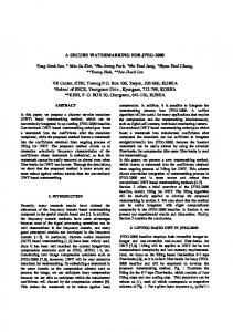
Figure 1: System Architecture of a Secure Digital Still Camera Several software based watermarking schemes have been presented in the literature; however, only a few hardware schemes have been proposed. Strycker, et. al. [4] proposed the implementation of a real-time spatial domain watermark embedder and detector on a Trimedia TM-1000 VLIW processor. Mathai, et. al. [5] present a chip implementation of the same video watermarking algorithm. A DCT domain invisible watermarking chip is presented by Tsai and Lu [6]. Garimella, et. al. [7] proposed a VLSI architecture for invisible-fragile watermarking in spatial domain. Mohanty, et. al. [8] described a watermarking chip that has spatial domain invisible robust and fragile watermarking functionalities. In this work, we focus on the VLSI implementation of two spatial domain visible watermarking schemes, one proposed by Braudaway, et. al. [9] and the other by Mohanty, et. al. [3]. The VLSI chip can insert either one or both the watermarks depending on the requirement of the user. The proposed watermarking chip can be integrated within any existing digital still camera. We provide the schematic view of a still camera that includes a watermarking module in Fig. 1, and call such a camera as a ”secure digital still camera”.
2 Watermarking Algorithms In this section, we outline the watermarking algorithms in brief with the modifications needed for hardware implementation. The notations listed in Table 1 are needed for describing the algorithms.
= 5jQTSKUeWlY s 8eI
5jQkSVUXW,Y =T6
Table 1: List of Variables used in Explanation �
: : : : : : : : : : : : : : : : : : : : : :
� ����� � �� ���������
�
���
��� � �
� �� � � � � � � � ! � � �#"%$�& � "(' � � "%$�& � "(' � �*) '
� � � ,� + -/. � -10 -(2 � -(3
Original (or host) grayscale image Watermark image (a grayscale image) A pixel location Watermarked image Original image dimension Watermark image dimension � ����� block of the original image � ����� block of the watermark image �� ����� block of the watermarked image Scaling factor for ����� block Embedding factor for ����� block � Mean gray value of the original image ��� Mean gray value of image block ��� Variance of the original image block � � The maximum value of � The minimum value of � � � The maximum value of � � The minimum value of Gray value corresponding to white pixel A global scaling factor Linear regression co-efficients Linear regression co-efficients
(3)
for
(1)
The above equation is further simplified to make the hardware implementation easier. At the same time, care is taken to make sure that the hardware is as accurate as the software 6�XI
C implementations. We assume y�y and simplify the above equations to the following.
for
9I;J=K?BADC
for
for
687:9I;J=K?BADC
EFF 6 9I;J=K?BABLPJ� MO9=@?BA169=@?BA FF {K|VZ]\ Z ` FF 69=@?BA FF ~ FF 6 9I;J=K?BABL P K MO9I;J=K?BA16 9I;J=K?BA FF ^]\ |V{V_K^T` FF t6 9I;J=K?BA ~z� MO9I;J=K?BA16 9I;J=K?BA P w G 6 9I;J=K?BABL ^]\ |V{V_K^T` FF 69=@?BA FF n ~ x FF 6 9I;J=K?BABLP(w z� MO9I;J=K?BA16 9I;J=K?BA FF ^]\ |V{V_K^ ` FF p 69=@?BA FF x ~¡ 8¢ FFH 6 9I;J=K?BABL P( K £ MO9I;J=K?BA16 9I;J=K?BA ^]\ |V{V_K^T` ¤69=@?BAo ¢ y�z
for
FF 6 9I;J=K?BABLNMO9I;J=K?BA1P 5RQTSVUXW,Y 58cedbf gih F ZK[]\ ^K^V_T`ba 5jQkSVUeWlY%monp 4%5 G 58cedbf gih 5jQkSVUeWlYrqtsvu sws�x�xkyiz FF FF 6 9I;J=K?BABLNMO9I;J=K?BA 58cedbf gih a {K|VZ]\ Z FH m 4}5 58cedbf gih 5jQkSVUeWlYr~tsvu sws�x�xkyiz
EFF 6 9I;J=K?BABLPw MO9=@?BA�9�6 9I;J=K?BA@A ^]\ |V{V_V^ ` 69=@?BA G np q u yixw FFH 6 9I;J=K?BABLP� MO9=@?BA@6 9I;J=K?BA {K|VZ]\ Z ` 69=@?BA ~ u yixw
5jQTSVUXW,Y
for
6 7
EFF
for
Z
5jQTSKUeWlY =
5jQkSVUeWlY
for
Algorithm 1 (Proposed in [9]) : The watermarked image is obtained by adding a scaled gray value of the image to the host image. The amount of scaling is done in such a way that the alternation of each original image pixel occurs perceptually by equal degree. The original formula is simplifed as follows, where the scaling factor 4%5 determines the strength of the watermark [10].
687:9=@?BADC
5jQTSVUXW,Y =
, , and , . We fit four linear regression co-efficients that best approximates the cubic root in each of these ranges. Moreover, we roundup the fraction involved in the comparison operation and the final simplified expression that is implemented using hardware is as follows.
such as Z
(2)
for
We further simplify the above expressions and remove the cubic root function with a piecewise linear model. We =T6 eI
* divide the gray values range s to four ranges,
Algorithm 2 (Proposed in [3]) : The pixel gray values are modified based on the local and global statistics. The watermaking insertion process consists of the following steps. 6 Both the host image (one to be watermarked) and the waM I termark (image) are divided into blocks of equal sizes (the two images may be of unequal size). Let ¥§¦ denoteI the ¨ 6 block of the original image and ©�¦ denote the ¨ block M of the watermark . For each block (¥§¦ ), the local statistics; mean ªB¦ 5 and variance « ¦ 5 are computed. The image mean gray value ª 5 is also found out. The watermarked image block is obtained by modifying ¥ ¦ as follows. 7 ¥
C ¦
4(¦¥§¦
L¬
¦©�¦
¨
C
=*
ulueu
(4)
¬
Where, 4 ¦ and ¦ are scaling and embedding factors respectively, depending on ª ¦ 5 and « ¦ 5 of each host image block. ¬ The choice of 4 ¦ and ¦ are governed by certain characteristics of human visual system (HVS) and mathematical models are proposed so that the perceptual quality of the image are not degraded due to watermark addition. The 4(¦ and ¬ ¬ ¦ are obtained as follows. The 4%¦ and ¦ for edge blocks ¬ ¬ are taken to be 4 d®�¯ and d g respectively. The 4(¦ and ¦ are found out using the following equations. ¬ ¹
¦ 4 ¦
C C
° P ¸ 9/¹ K ª ¦ 5 ²´± ³ k µ¶�· ¹ P ¸ P@¸ «¦ 5 µ ¶w· ¹
¸
¹ A ` ª5 9º¹ ¹ A ¸ `` ªB¦ 5 ª 5
(5)
Where, ª ¦ 5 and ª5 are normalised values of ª ¦ 5 and ª5 , ¹ and « ¦ 5 are normalised logarithm values of « ¦ 5 . The 4 ¦ and ¬ ¬ ¬ ¦ are scaled to the ranges ( 4}d g , 4%d®�¯ ) and ( d g , d®�¯ ) respectively, where 4}d g and 4%d®�¯ are minimum and max¬ ¬ imum values of scaling factor, and d g and d®�¯ are minimum and maximum values of embedding factor. These parameters determine the extent of watermark insertion. A lin¬ ear transformation is used to scale¬ current 4 ¦ and ¦ values ¬ to the ranges ( 4 d g , 4 d®�¯ ) and ( d g , d®�¯ ), respectively.
Let current values of 4 ¦ be written as 4%»¦ , and 4%d» g and 4(do » �¯ , respectively denote the current minimum and maxi¬ mum values. Similarly, let current values of ¦ be written ¬ ¬ ¬ as ¦ » , and d » g and d® » �¯ , respectively denote the current ¬ minimum and maximum values. The 4 ¦ and ¦ values are scaled as follows.
I(m,n)
Comparator
Register File
I(m,n)
W(m,n)
α
Multiplier
α α
I
Multiplier
Edge Detection Unit
k
and β k Calculation Unit
max
0
W(m,n)
α
β min
k
1
0
Multiplier
C ¦
4 ¬
�¼}½@¾´¿�¼ UXÀ L a w } ¼Á ½@¾ ¿ ¼Á UXÀ m 4%»¦ ¼B½K¾ ¿ ¼ eU À ¬ L avà ¼B Á ½K¾ ¿ à ¼ Á eU À m ¦» à Ã
C ¦
¬ a
�¼B½K¾Â¿�¼ XU À a w » �¯ m B ¼Á ½K¾ ¿ ¼Á XU À m 4%d® ¼}½@¾ ¿ ¼ UXÀ ¬ aÄà ¼} Á ½@¾ ¿ à ¼ Á UXÀ m d » �¯ m ® à à ¸
a 4%d®�¯ ¸
d®�¯
ÅÊÍ
° Î%Ï1ÐÄÎ%ÏÒÑ d
Ñ g
Å
9=@?BA
(6)
¹
¦ 5
C
;
° ÐÓÎ Ï
Î
Ï
° 5jQkSVUeWlYwm a
Ñ d
Ñ
W
6 9I;J=K?BA
(8) I
Where, and are the pixel locations of the ¨ image block, same as their locations in the original image. The norI malized standard deviation of gray values for the ¨ block is calculated as follows. ¹ « ¦ 5
C
° ÐÓÎ Ï
Î
Ï a
Ñ
5jQTSVUXW,Ywm
d
Ñ
6 9I;J=K?BA gÔ Ô
¸
5RQTSVUXW,Y Ô Ô
(9)
The exponential term in Eqn. 5 is approximated as a Taylor series upto the square term. In step three of the insertion algorithm, scaling needs to be done using a linear transformation, to find the¬ current minimum and maximum values for both 4%¦ and ¦ over all the blocks. The hardware performance is going to be severely degraded since it has to wait till all the pixels of the images are processed to derive the local statistics of all the blocks. So, we modify the above Eqn. 5 to ensure that the performance of the hardware is improved with no compromise on ¬ the quality. We find 4 ¦ and ¦ using the following equations. ¬
4(¦ ¦
C C¬
4 d
d
g
g
LJ9 L9I¬
4
d®�¯ d®�¯
¸
¸ ¬ d
4
A 9 ¹ ¹ A P ¸ / @ ¸ ° ` ª ¦ 5 B ª 5 g ² ±³ µ ¶w· P ¸ P ¸ 9Õ¹ A ¹ A ¸ ¹ ` ` g « ¦ 5 ª ¦ 5 ª 5 µ ¶�· d
Adder
(a) For Algorithm 1
I (m,n) W
(b) For Algorithm 2
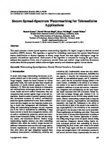
Figure 2: Datapath Architectures for the Algorithms
3 VLSI Architecture
(7)
g
?
Adder
I (m,n)
When the mean amplitude for a block exceeds a predefined ; threshold, we declare it as an edge block. The values of ? and correspond to the pixel locations of individual blocks with reference to the original image pixel location. The mean gray value of a block is calculated as the average of the gray values of all pixels in the image block. The mean gray values are normalized with pure white pixel gray value. Thus, the normalized mean gray values of a block is, ª
Multiplier
Multiplier
We used first-order derivatives for edge detection. For horizontal edge detection, we compute the horizontal gradiv9I;J=K?BAÆCÇ69=@?BA ¸ 6 9I;ÈL =@?BA ent as : Å . The vertical 9=@?BADCË6 9I;J =K?BA ¸ 69=@?¤L A gradient is computed as ÅÊÉ for vertical edge detection. The amplitude of an edge is cal9I;J=K?BA/CÌ 9=@?BA8Ì8LÌ 9=@?BA]Ì culated as, Å . The mean Å ÅÊÉ amplitude for a block is computed as, C
βk 1
(10)
Extensive simulations for various images show that the 4 ¦ ¬ and ¦ obtained using Eqn. 6 and Eqn. 10 are comparable (maximum difference is ykÖ [1]).
We develop an architecture for the first algorithm shown in Fig. 2(a). A register file is used to store the constants needed to scale the image-watermark product in Eqn. 3. We £ ° store the constants {K|VZ]\ Z , ^�\ |*{V_K^ , ^]\ |V{V_V^ , ^�\ |*{K_V^ , and ^�\ |*{V_K^ p and the other constant 4%5 is assumedn as a parameter. The comparator is used to determine the range in which a particular pixel gray value lies, such that an appropriate constant can be picked up from the register file. The left side multiplier calculates appropriate constant times the host image pixel gray values and the right side multiplier is used to find 4 5 times the watermark image pixel gray value. The results of the above two multipliers are fed to the third multiplier which effectively calculates the product of constants, 4%5 , the host image pixel gray value, and the watermark image pixel gray value, respectively. The product is added to the host image pixel gray values using the adder to obtain watermarked image pixel gray values. The above described process is carried out for all the pixels to obtain the watermarked image. The architecture being proposed for the second algorithm is shown in Fig. 2(b)¬ which present the operation at pixel level. The ” 4%¦ and ¦ I calculation unit” computes the 4(¦ ¬ and ¦ values for the ¨ non-edge block using expression in Eqn. 10. The ”edge detection unit” determines if a block is an edge block or non-edge block. If the Å Í exceeds an user defined threshold, then it is an edge-block. Larger the threshold more are the blocks declared as edge-blocks. The multiplexors help in selecting the scaling and embedding factors between the edge and non-edge blocks. The multiplier on the left calculates the scaling factors times the host image pixel gray value. The right side multiplier multiplies the embedding factor with the watermark image pixel gray value. The products from these two multipliers are added using an adder to find the watermarked image pixel gray value. This process is repeated for all pixels in a block, and subsequently for all the blocks in the image.
¹
I(m,n) 128
Adder
Adder / Subtractor
Accumulator
Adder 1 16384
I(m+1,n)
Multiplier
I(m,n)
I(m,n+1)
Accumulator