This article has been accepted for publication in a future issue of this journal, but has not been fully edited. Content may change prior to final publication. Citation information: DOI 10.1109/TNANO.2018.2811958, IEEE Transactions on Nanotechnology
Vortex-Driven Rotation for Three-Dimensional Imaging under Microscopy Xiaoming Liu, Student Member, IEEE, Qing Shi, Member, IEEE, Yuqing Lin, Masaru Kojima, Yasushi Mae, Qiang Huang, Fellow, IEEE, Toshio Fukuda, Life Fellow, IEEE and Tatsuo Arai, Fellow, IEEE Abstract—The noninvasive rotary motion of bio-objects for three-dimensional (3D) observation and posture adjustment has been a great challenge in micro robotics. This paper reports a harmless non-contact 360° rotation method with a controllable velocity, which applied the vortex induced by vibrating the micro pipette in an open fluidic environment. The micro pipette was driven by a piezo actuator which was mounted on a copper pillar. By generating a resonance between the copper pillar and the piezo actuator fed with sine wave of a specific frequency, we controlled the micro pipette to vibrate circularly. The vibration-induced vortex around the micro pipette could trap micro objects close to it, and then drive the trapped objects to rotate with the uneven drag force acting on their surface. Experiments of 360°rotation of the micro beads were carried out to demonstrate this method and analyze the rotation velocity. An application in 3D imaging under optical inverted microscopy was achieved. The spheroids assembled by single cells were rotated, which enabled us to observe the different aspects of the cell spheroids and reconstruct its 3D view. Index Terms—micro robotics, rotary motion, microscopy, three-dimensional imaging.
I. INTRODUCTION
N
O matter in macro or micro scale, transportation and rotation are two fairly common mechanical motions [1], [2]. Recently, advances in micro robotics enable us to manipulate and analyze biological objects in micro scale [3]. However, as one of the basic operation in micromanipulation, noninvasive rotation of a micro biological object is still one of the biggest challenges we are facing now [4]. Rotating biological object in micro scale is a fundamental technique in the biological research. For example, rotation of the objects with an axis vertical to the axis of the objective lens can expose different aspects to the light for three-dimensional (3D) observation under optical microscopy [5]. Such 3D observation is especially significant in the observation and This work was supported by the National Natural Science Foundation of China under Grants 61433010, 61520106011, Beijing Nova Program under Grant Z161100004916071, and the Grant-in-Aid for Scientific Research (JP23106005, JP16H06076) from the Ministry of Education, Culture, Sports, Science and Technology of Japan. X. Liu, Q. Shi, Y. Lin, Q. Huang, T. Fukuda and T. Arai are with Beijing Advanced Innovation Center for Intelligent Robots and Systems and the Intelligent Robotics Institute, School of Mechatronical Engineering, Beijing Institute of Technology, Beijing 100081, China (phone: +86-15101117324; fax: +86-10-68915812; e-mail: liuxiaoming555@ bit.edu.cn). M. Kojima and Y. Mae are with the Department of Systems Innovation, Osaka University, 1-3, Machikaneyama, Toyonaka, Osaka, 560-8531 JAPAN. Copyright (c) 2018 IEEE. Personal use of this material is permitted. However, permission to use this material for any other other purposes must be obtained from the IEEE by sending a request to
[email protected] .
manipulation of a biological object with asymmetric 3D structures and low transparency. Besides, rotation of micro objects is also necessary in cell assembly (posture adjustment before assembling asymmetric cellular structures), in vitro fertilization (orientation control before sperm injection) and enucleation [6], [7]. In these biological operations, viability of the objects is paramount which requires such biological objects to be rotated noninvasively for further operation or culturing [8]. In most biological research and clinical operations under the optical microscopy, well-trained operators can utilize a micro pipette to keep absorbing and releasing the object until the it is properly rotated to the targeted gesture [6]. Such manual operation is a typical trial-and-error method with an extremely low controllability and low accuracy. Thus, operators need extensive training and lots of practice to be skilled in the manual rotation. Even though, the biological viability still varies due to the low reproducibility and long time cost. Therefore, a controllable and highly reproducible robotic rotation method in microscale is in demand. Robotic rotation in micro scale under the optical microscopy mainly includes two types: rotation axis parallel to the axis of the objective lens (PR) and rotation axis vertical to the axis of the objective lens (VR). PR can be achieved by conventional stages. However, for 3D observation, PR cannot change the views under the microscopy. Conventional robotic VR is often realized by the cooperation of two micromanipulators which hold different parts of the micro object [9]. The object can be rotated via relative movement between the two micromanipulators. However, such 3D manipulation demands extremely complex system setup and precise position control which diminishes the efficiency a lot [10]. In a similar way, VR by optical tweezers has also been reported to realize the rotation of targets (≤ 100 μm) with a pair of closely separated optical traps [11]. However, both two methods might bring potential damages to the living cells because of the mechanical contact or strong laser power. Recently, microfluidic chips with flow generated by the walls or magnetic field driven end-effector inside emerged as a promising noninvasive PR and VR rotation method [12], [13]. The closed environment of the microfluidic chips made object extraction, further operation and time lapse observation difficult. Besides, the fixed predesigned channel size limited object selection. However, micromanipulation driven by flow has been attracting attention of many researchers in micro robotics. Our team have successfully generated micro flow by microbubbles and vibration, and applied them in the micro
1536-125X (c) 2018 IEEE. Personal use is permitted, but republication/redistribution requires IEEE permission. See http://www.ieee.org/publications_standards/publications/rights/index.html for more information.
This article has been accepted for publication in a future issue of this journal, but has not been fully edited. Content may change prior to final publication. Citation information: DOI 10.1109/TNANO.2018.2811958, IEEE Transactions on Nanotechnology
2
Fig. 1. The schematic drawing of the rotation driven by the vortex induced by circular vibration of the micro pipette.
assembly and release of the micro objects adhering on the end-effector respectively [14]. In this paper, a harmless non-contact 360°rotation method with a controllable velocity driven by a micro vortex flow in open environment is reported. Electric sine waves were applied to a single piezo actuator to drive the micro pipette to vibrate circularly, as shown in Fig. 1. The vortex induced by the circular vibration could trap objects around and rotate the trapped objects by the uneven drag force acting on the surface of the object. Rotation of microbeads was demonstrated and utilized to analyze the rotation velocity. Finally, the spheroids assembled by single cells were rotated and the different views of the cell spheroids were observed. These views were further applied to the 3D reconstruction of the cell spheroids.
Fig. 2. Vortex-driven rotation system setup.
II. SYSTEM SETUP The micro robotic system we set up for the rotation of micro object mainly included three parts: a vibration unit, motorized micromanipulator and an optical observation system. As shown in Fig. 2, in the vibration unit, a single piezo actuator (AE0203D16, NEC-Tokin) with a length of 20 mm and a maximum elongation of 17.4 μm was utilized in the system and it was powered by the piezo driver (PZJ-0.15P, Matsusada Precision Inc.). The control signal generated by a function generator (AFG-2225, GW Instek) was amplified up to 15 times by the piezo driver before being applied to the piezo actuator. A micro pipette pulled by needle puller (PC-10, NARISHIGE) was fixed on one end of the piezo actuator. The piezo actuator together with the micro pipette was mounted on a copper pillar with an outer diameter of 6 mm. A manual stage was involved to hold the copper pillar and adjust the micro pipette position in the initial setup. The length between the holding position and the end of the copper pillar was set to 60 mm. The system also included a motorized XYZ stage (TAM-655, Sigma koki) to position the micro pipette during the operation. Each axis of the micromanipulator was driven by a 5phase stepper motor (SGSP-13ACT-B0, Sigma koki). It was powered by a stepper motor driver (SG-55MA, Sigma koki) and controlled by the PC through a MCU (mbed NXP LPC1768). In the optical observation system, inverted optical microscopy (IX73, Olympus) imaged by a high speed camera (MC-2, Photron) was adopted. The maximum frame rate of 2000 fps enabled us to analyze the high-speed movement of the vibrated micro pipette.
Fig. 3. Working principle of the rotation using vortex induced by circular vibration.
III. PRINCIPLES OF THE VORTEX-DRIVEN ROTATION Fig. 3 illustrates the working principle of the micro object rotation using vortex induced by single piezo actuator driven vibration in an open fluidic environment. It mainly includes two reactions among the micro pipette, fluids and the micro objects. In Part A of this section, vortex induced by the circular vibration of the micro pipette (reaction between micro pipette and fluids) will be introduced, then rotation driven by the vortex (reaction between fluids and objects) will be described in Part B. A. Vortex induced by the Circular Vibration In the vortex generation, controlling the micro pipette to vibrate circularly is the key. The system shown in Fig. 2 was previously set up for active release of the object adhering on the end-effector by vibrating the glass needle. The single piezo actuator driven glass needle was supposed to vibrate in one dimension. However, in experiments we found that the trajectory of the motion of the micro pipette was an ellipse in most cases. The reason for this phenomenon was that the vibration of the piezo could also cause the resonance of the copper pillar. The displacement of the micro pipette was the
1536-125X (c) 2018 IEEE. Personal use is permitted, but republication/redistribution requires IEEE permission. See http://www.ieee.org/publications_standards/publications/rights/index.html for more information.
This article has been accepted for publication in a future issue of this journal, but has not been fully edited. Content may change prior to final publication. Citation information: DOI 10.1109/TNANO.2018.2811958, IEEE Transactions on Nanotechnology
3
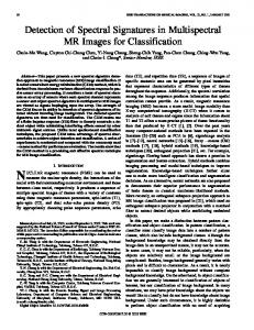
Fig. 4. (a) The schematic drawing of generation of the circular vibration of the micro pipette. (b) Relationship between the Vpp (Peak-peak voltage of the sine waves applied to the piezo actuator) and the amplitude of circular vibration of the micro pipette. Insets are the side view of the circular vibration and vortex visualized by micro beads with outer diameter of 9.7 μm.
vector sum of the displacement of the copper pillar and the displacement of the piezo actuator, as shown in Fig. 4 (a). Such kind of resonance was very sensitive to the frequencies. The shape of the trajectory of the micro pipette changed when we adjusted the frequency of the electric sine waves applied to the piezo actuator. A standard circle trajectory could also be achieved when the frequency was set to 350 Hz under the setup shown in Fig. 2. Microbeads with outer diameter of 9.7 μm were utilized to visualize the vortex induced by the circular vibration of the micro pipette in an open fluidic environment. We also found that the vibration amplitude of the micro pipette varied when we adjusted the Vpp (Peak-peak voltage of the sine waves applied to the piezo actuator). An approximate linear relationship between the Vpp and the amplitude of circular vibration of the micro pipette was found, as shown in Fig. 4 (b). This law enabled us to control the rotation velocity. B. Rotation Driven by Vortex The vortex induced by the circular vibration featured with two main properties: fluid motion in a vortex created a low pressure in the core region and the velocity of the flow close to the core region was much larger than that of the one far away. The first property enabled the vortex to trap the micro object and keep it close to the core region. As shown in Fig. 3, the rotation of the micro object was driven by the drag force acting on the surface. The drag force in micro scale depended linearly on the flow velocity. The flow velocity changing continuously from the core region to the distance led to the uneven drag force
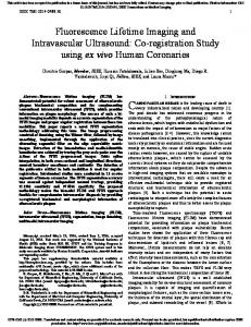
Fig. 5. Vortex driven rotation of micro beads with outer diameter of 97 μm in water. (a), (b) Rotation of micro beads along X axis with 135 V and 30 V Vpp. (c) Relationship between the rotation angular velocity and Vpp (Peak-peak voltage of the sine waves applied to the piezo actuator)
which could generate a torque to drive the micro object rotate. The flow velocity in the circular vibration induced vortex was also influenced by the amplitude of the vibration. As we demonstrated in Part A of this section, the amplitude of the circular vibration depended linearly on the Vpp of the electric sine wave applied on the piezo actuator. In the rotation method presented in this paper, the Vpp was utilized to control the rotation velocity of the micro objects. Experiments of rotation of the micro beads with an outer diameter of 97 μm (1.05 g/cm3, Duke scientific) were carried out to demonstrate our rotation method and the velocity control by adjusting Vpp. The micro beads were maintained in a water droplet and lying on the bottom due to its little higher density compared with the water. We usually set the distance between the tip of the micro pipette and the bottom as the radius of the object. As shown in Fig. 5 (a) and (b), the rotation could be observed clearly with the displacement of the small bubble (black impurity) inside of the micro bead. The stable continuous 360° non-contact rotation around X axis was realized. By adjusting the Vpp from 30 V to 135 V at the frequency of 350 Hz, the rotation angular velocity of the micro bead reached up to 5.48 rad/s, and also could be as lowered as 0.26 rad/s. Finally, as shown in Fig. 5 (c), the positive correlation between the rotation angular velocity and Vpp was demonstrated experimentally. The rotation angular velocity being controlled by Vpp ranging from 0.26 rad/s to 5.48 rad/s make this rotation method accessible in lots of applications previously mentioned in the introduction of this paper.
1536-125X (c) 2018 IEEE. Personal use is permitted, but republication/redistribution requires IEEE permission. See http://www.ieee.org/publications_standards/publications/rights/index.html for more information.
This article has been accepted for publication in a future issue of this journal, but has not been fully edited. Content may change prior to final publication. Citation information: DOI 10.1109/TNANO.2018.2811958, IEEE Transactions on Nanotechnology
4
Fig. 6. (a-h) Vortex driven rotation of the cell spheroid in PBS. (i-l) The application of the rotation in 3D imaging of the cell spheroid.
IV. APPLICATION IN 3D IMAGING A significant application of this rotation method is the 3D imaging under microscopy due to its VR rotation, controllable 360 °rotation and noninvasive operation with the fluidic force. As shown in Fig. 6, a spheroid assembled by the single cells (Fibroblasts, NIH/3T3) were rotated 360° continuously and stably in phosphate-buffered saline (PBS, Wako) under inverted optical microscopy to expose its different aspects to the light, which can be observed by a cell marked with white arrow in Fig 6 (a)-(h). It enabled us to check the viability of the cells distributed in different parts of the spheroid, which is very important in our research on the regeneration of microvessel by assembling cell spheroids in a bottom-up way [14]. The figures shown in Fig. 6 were taken after rotating the spheroids more than 5 minutes. Few cells were found dead which demonstrated that the rotation method we developed was harmless to living cells. During the rotation, we took a picture around every 22°. Finally, 16 pictures showing different aspects of the spheroid were obtained and further processed by a 3D reconstruction software (Agisoft PhotoScan), as shown in Fig. 6 (i)-(l). The background of original figures were first eliminated. Then, after feature recognition and alignment, 3D view of the spheroid was reconstructed. V. CONCLUSION In summary, we proposed a novel vortex driven rotation method. 360°continuous rotation with a controllable rotation angular velocity ranging from 0.26 rad/s and 5.48 rad/s has been experimentally demonstrated by rotating micro beads. Application in 3D imaging of the cell spheroid has been shown under the optical inverted microscopy, and this method has been proved harmless to the living cells. In the future, this rotation method will be further applied in the egg cell orientation control before in vitro fertilization and posture adjustment in assembly of asymmetric cellular structures.
REFERENCES [1]
[2]
[3]
[4] [5]
[6]
[7]
[8]
[9]
[10]
[11]
[12]
[13]
[14]
M. Hagiwara, T. Kawahara, F. Arai, Local streamline generation by mechanical oscillation in a microfluidic chip for noncontact cell manipulations, Applied Physics Letters, vol. 101, no. 7, 074102, 2012 L. Dong, et al, "Dual-Chirality Helical Nanobelts: Linear-to-Rotary Motion Converters for Three-Dimensional Microscopy," Journal of Microelectromechanical Systems, vol. 18, no. 5, pp. 1047-1053, Oct. 2009. M. Hagiwara, T. Kawahara, Y. Yamanishi, T. Masuda, L. Feng, F. Arai, “On-chip magnetically actuated robot with ultrasonic vibration for single cell manipulations”, Lab on a Chip, vol. 11, no. 12, pp. 2049-2054, 2011 N. Li and J. Hu, “Multi-functional manipulations of microobjects based on electrolysis of water”, Applied Physics Letters, 103, 124101, 2013. H. Takeshi, S. Sakuma, and F. Arai. "On-chip 3D rotation of oocyte based on a vibration-induced local whirling flow," Microsystems & Nanoengineering, 15001, Jan. 2015. X. Liu, Z. Lu and Y. Sun, “Orientation Control of Biological Cells Under Inverted Microscopy,” IEEE/ASME Transactions on Mechatronics, vol. 16, no. 5, pp. 918-924, Oct. 2011. C. Leung, Z. Lu, X. P. Zhang and Y. Sun, "Three-Dimensional Rotation of Mouse Embryos," IEEE Transactions on Biomedical Engineering, vol. 59, no. 4, pp. 1049-1056, April 2012. L. Feng, B. Turan, U. Ningga and F. Arai, "Three dimensional rotation of bovine oocyte by using magnetically driven on-chip robot," 2014 IEEE/RSJ International Conference on Intelligent Robots and Systems, Chicago, IL, 2014, pp. 4668-4673. H. Xie and S. Regnier, “Development of a flexible robotic system for multiscale applications of micro/nanoscale manipulation and assembly,” IEEE/ASME Trans. Mechatronics, vol. 16, no. 2, pp. 266-276, Feb. 2011. T. Tanikawa and T. Arai, “Development of a micro-manipulation system having a two-fingered micro-hand,” IEEE Trans. Robot. Autom., vol. 15, no. 1, pp. 152–162, Aug. 1999. V. Bingelyte1, et al, “Optically controlled three-dimensional rotation of microscopic objects”, Appl. Phys. Lett. Vol. 82, no.5, pp. 829-831, Jan. 2003. T. Yue, et al. “On-chip Self-assembly of Cell Embedded Microstructures to Vascular-like Microtubes,” Lab on a Chip, vol.14, pp.1151-1161, 2014. Hayakawa, Takeshi, et al. "A Single Cell Extraction Chip Using Vibration-Induced Whirling Flow and a Thermo-Responsive Gel Pattern," Micromachines, pp. 681-696, Sep. 2014. X. Liu and T. Fukuda et al., "Automated Fluidic Assembly of Microvessel-Like Structures Using a Multi-Micromanipulator System," IEEE/ASME Transactions on Mechatronics, doi: 10.1109/TMECH.2018.2796182
1536-125X (c) 2018 IEEE. Personal use is permitted, but republication/redistribution requires IEEE permission. See http://www.ieee.org/publications_standards/publications/rights/index.html for more information.