dominant vortex ring of the pair, which consists of vorticity from the wake, persists ... The collision breaks cohesive bonds between the dust particles and, if the ...
Conference on Bluff Body Wakes and Vortex-Induced Vibrations (BBVIV3) Port Douglas, Australia 17-20 December, 2002
Vortex Dynamics of Particle Interactions with Walls Mark C Thompsona , Thomas Lewekeb , Alex Cheunga & Kerry Hourigana a
Fluids Laboratory for Aeronautical and Industrial Research (FLAIR) Department of Mechanical Engineering Monash University, Melbourne, 3800, Australia b
Institut de Recherche sur les Ph´enom`enes Hors Equilibre 49 Rue F. Joliot-Curie, BP. 146, 13384 Marseille Cedex 13, France
For moderate Reynolds numbers, a sphere striking a wall in the normal direction will lead to the trailing wake threading over the sphere and forming a pair of counter-rotating vortex rings which strikes the wall. The dominant vortex ring of the pair, which consists of vorticity from the wake, persists and convects outwards away from the sphere, presumably due to the induced motion from its image vortex. In this article, numerical and experimental techniques are used to study this flow. The interaction of the vortical structures is presented in terms of a sequence of visualisations of the vorticity fields. Passive tracer particles are used to visualise the effect on a layer of particles (e.g., dust) on the surface. The evolution of the position and strength of the main vortex ring is quantified.
1. INTRODUCTION When a rigid body collides with a surface, a layer of dust on the surface can be resuspended due to the effects of two different mechanisms recently described by Eames & Dalziel (2000). The first is a ballistic mechanism. The collision breaks cohesive bonds between the dust particles and, if the kinetic energy is sufficiently large, this can lead to the ballistic ejection of particles from the wall. For dust ejection by sand particles, experiments by Rice, Willetts & McEwan (1996), and Shao, Raupach & Findlater (1993) related the mass ejection rate to the collision rate and the energy loss per collision. The second mechanism leading to dust ejection is hydrodynamic; this is the focus of the current study. At Reynolds numbers in excess of approximately 100, the wake flow following the rigid body overtakes it on impact and resultant ring vortex structure(s) can cause significant dust resuspension. More recently Eames & Dalziel (2000) have examined the behaviour in more detail as the Reynolds number was varied between 300 and 3500. In that study, the analysis was primarily directed towards resuspension characteristics of different dust types and layer thicknesses rather than the fluid dynamics, which is of primary concern in this paper. Joseph et al. (2001) experimentally examined particle-wall collisions for Reynolds numbers between 10 and 3000 and showed that the rebound was primarily a function of the Stokes number. Both Joseph et al. (2001), and Gondret, Lance & Petit (2002) determined the coefficient of restitution as a function of Stokes number and showed that it reaches an asymptotic value for high Stokes number corresponding to the value for dry collisions. Note that particle impacts with walls also have importance for other areas as well such as enhancement of heat transfer due to the convection of fluid towards and way from the surface through wake structures. In this paper the fluid dynamics associated with the impact is explored using both experimental and numerical methods. Only the restricted case of a spherical body impacting a wall normally is considered.
2. METHODOLOGY 2.1. NUMERICAL METHOD The spectral-element method (e.g., Karniadakis & Sherwin 1999) is employed to study the interaction numerically. An existing in-house axisymmetric spectral-element code, which has been validated extensively (e.g., Thompson, Leweke & Provansal 2001; Sheard, Thompson & Hourigan 2001), has been modified to treat the particle impact. The modification is based on the ALE (Arbitrary Lagrangian-Eulerian) method described in
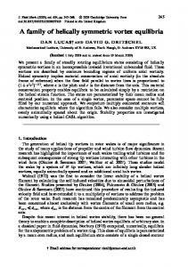
Warburton & Karniadakis (1997). As the sphere moves towards the surface, the vertices of the mesh move with predetermined specified velocities so that the semi-circular boundary of the sphere (in the axisymmetric coordinate system) is maintained and the mesh does not become too distorted. The computational boundaries are placed sufficiently far from the sphere so that the blockage effect is negligible. A computational domain and mesh are shown Figure 1. This corresponds to the initial time before the sphere is instantaneously accelerated to the right to a (non-dimensionalised) velocity of unity.
Figure 1. Left: Mesh system for the numerical calculation. The outer boundaries are at 25D from the sphere. Only macro-elements shown.
For the simulations described in this paper, the initial distance from the wall was 25D, where D is the sphere diameter. This allows the wake to become almost fully-developed before the particle impact occurs. Visualisations from experiments performed after the numerical simulations indicated that it is difficult to maintain axisymmetry of the wake for initial distances beyond about 5-10D. Further numerical simulations are currently underway using the experimental distances, however, the predicted wake dynamics suggests that this change is unlikely to affect the main findings. The sphere is stopped at 0.005D from the wall to avoid mesh singularity problems. Despite the significant final skewness of the mesh at that time, further time integration during the flow evolution stage is quite stable.
2.2. EXPERIMENTAL TECHNIQUES The experiments were carried out in a 50 × 50 × 50 cm3 glass tank filled with water. A metal ball 19.02 mm in diameter was attached to a fine twisted nylon thread. The thread passed over a pulley and was wound on a threaded reel driven by a computer-controlled stepper motor. This mechanism allowed the sphere to be lowered through the water at a specified speed, thereby allowing specification of the Reynolds number. Fluorescein dye and light from an Argon ion laser were used to visualise the wake vortical structures and the formation and advection of the vortex ring structures as the wake threaded over the sphere on impact. All of the experimental sphere impact studies were conducted with an initial distance from the wall of 5D.
3. RESULTS 3.1. VISUALISATION OF VORTICITY AND PARTICLE MOTION Simulations were performed at Re = 100, 500 and 800. The evolution was followed for a non-dimensional time of at least 16 units after the collision. It was visualised through the azimuthal vorticity distribution in the neighbourhood of the sphere. In addition passive tracer particles were introduced at the walls at the time of impact. They were distributed randomly out to a distance of 0.1D and their positions integrated in time to visualise the effect of dust or dye at the surface. Figure 2 shows the vortical flow patterns and particle resuspension for the three Reynolds number investigated. The visualisations correspond to non-dimensional times of τ = tU/D = 2, 4, 8, 16, respectively, from left to right. (One time unit corresponds to the time taken for the sphere to move one diameter.) At Re = 100, while the trailing wake threads over the sphere on impact, there is little effect on the surface particles. No particles are actually ejected from the surface although there is slight shifting of particles due to the induced convective motion of the vortical ring structure. At τ = 16, the vorticity originally from the wake has diffused and cross-annihilated substantially so that the particle distribution shown at that time is close to the
Figure 2. Top three sequences: Vorticity and resuspended particle patterns for sphere impacts at different Reynolds numbers from the numerical calculations. Top to Bottom: Re = 100, 500 and 800 respectively. Left to Right: Non-dimensional times after impact of τ = 2, 4, 8, 16, respectively. Last two sequences: Experimental dye visualisations of the sphere impact for Re = 500 and 800 at the same times as for the numerical snapshots.
final distribution. The details of the experimental visualisations and the numerical predictions, e.g., time of vortex rings impact with the wall, final position of the ring vortex, and development and evolution of vortical structures, agree well given the difference in starting distance. At the two higher Reynolds numbers studied, the flow structures are much more interesting. In both cases, a pair of counter-rotating vortex rings form as the anticlockwise vorticity from the wake passes over the top of the sphere which is paired with clockwise vorticity shed from the sphere surface. At approximately τ = 2, the
vortex pair reaches the surface and the particles are convected away from where the pair strikes the surface. Each of the vorticity and particle distributions are similar at this time for both Re = 500 and Re = 800. During the next two time units, differences in the vorticity distributions develop. The circulation from the wake is stronger than that generated at the surface of the sphere, hence the anticlockwise vorticity dominates. The clockwise vorticity is wrapped around the anticlockwise vorticity at τ = 4. There is still effectively a vortex (ring) pair at this time. For the higher Reynolds number the trailing clockwise vorticity breaks up into semi-discrete structures, whereas at the lower Reynolds number, the vorticity trails remain continuous. This is probably the result of a centrifugal instability which at the higher Reynolds number is not sufficiently damped to prevent the voriticity tails breaking up. At τ = 8, the effect is more pronounced with two distinct clockwise vortical satellites orbiting the still strong anticlockwise vortex ring. At a later time, (not shown), three distinct clockwise vorticity satellites are clearly visible. In both cases, the region cleared out by the hydrodynamic interaction is similar but the particle distribution is considerably more complicated for the higher Reynolds number case. For Re = 800, the final snapshot at t = 16 indicates that some of the anticlockwise vorticity from initial wake is being pulled around the established anticlockwise vortex ring, presumably due to the action of the clockwise rotating satellite vortices.
3.2. TRAJECTORY OF THE RING VORTEX For the Re = 500 case, the position of the centre and peak vorticity of the anticlockwise rotating ring vortex was recorded as a function of time. These characteristics are shown in Figures 3(a) and 3(b). maximum azimuthal vorticity
2.0
y/D
1.5 1.0 τ=1 τ = 25
0.5 0.0 0.0
0.5
1.0
1.5 x/D
2.0
2.5
3.0
10 8 6 4 2 0 0
5
10
τ
15
20
25
Figure 3. Left: Trajectory of main vortex ring for Re = 500. Right: Decay of maximum vorticity of the ring as the flow evolves.
The vortex ring is located 1.8D from the centre of the sphere at τ = 25. At this stage it is still moving away slowly. The peak vorticity decays exponentially in the long term. REFERENCES 1. EAMES, I. and DALZIEL, S.B. 2000 Dust Resuspension by the Flow around an Impacting Sphere J. Fluid Mech. 403, 305–328. 2. GONDRET, P., LANCE, M. & PETIT, L. 2002 Bouncing Motion of Spherical Particles in Fluids Phys. Fluids 14, 2, 643–652. 3. JOSEPH, G.G., ZENIT, R., HUNT, M.L. & ROSENWINKEL, A.M. 2001 Particle-Wall Collisions in a Viscous Fluid, J. Fluid Mech. 433, 329–346. 4. KARNIADAKIS, G.Em. & SHERWIN, S.J. 1999 Spectral/hp Element Methods for CFD Oxford University Press. 5. RICE, M.A., WILLETTS, B.B. & McEWAN, I.K. 1996 Wind Erosion of Crusted Solid Sediments, Earth Surface Processes and Landforms 21, 279–293. 6. SHAO, Y., RAUPACH, M.R. & FINDLATER, P.A. 1993 Effect of Saltation Bombardment on the Entrainment of Dust by the Wind J. Geophys. R. 98, 12719–12726. 7. SHEARD, G., THOMPSON, M.C. & HOURIGAN, K. 2001 A Numerical Study of Bluff Ring Wake Stability Proceedings of 14th Australasian Fluid Mechanics Conference, editor B. Dally, Adelaide University, December 2001, 401–405. 8. THOMPSON, M.C., LEWEKE, Th. and PROVANSAL, M. 2001 Kinematics and Dynamics of Sphere Wake Transition J. Fluids Struct. 15, 3/4, 575–585. 9. WARBURTON, T.C. & KARNIADAKIS, G.Em. 1997 Spectral Simulations of Flow Past a Cylinder Close to a Free Surface ASME paper FEDSM97-3389, 1997.