Our first prototype simulated the new UNC Computer Science building with some 8000 polygons. BSP-tree software on the Adage Ikonas gave a colored, ...
A INTERACTIVE 3D GRAPHICS %@
Walkthrough A Dynamic
Graphics
System Frederick
Department University
0.1
-
for Simulating P. Brooks, of Computer
Virtual
Buildings
Jr. Science
of North Carolina at Chapel Hill
Abstract
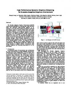
As part of our graphics research into virtual worlds, we are building a tool for an architect and his client to use for rapid prototyping of buildings by visually “walking through” them in order to refine specifications. Our first prototype
simulated
the new UNC Computer
Science building
with
some 8000 polygons. BSP-tree software on the Adage Ikonas gave a colored, shaded perspective view every 3-5 seconds while the user moved a cursor in real-time over floorplans shown on the Vector-General 3300. The current (third) version uses Pixel-Planes view images shown 4’ x 6’ by projector.
to generate 9 updates/second,
Active short- and long-term research questions include speed-up, stereo, a 6-DoF interface with eye-level defaults, and an interactive
model-building,
model-changing
system.
0.2
Application
Concept
At the 1965 IFIP Congress, Ivan Sutherland
challenged computer graphicists to
look beyond “the picture in the window” toward creating virtual environments in which the viewer is immersed, and where he sees, feels, and manipulates the virtual objects as if they were real. Much of the research at Chapel Hill has been aimed at this objective. The Walkthrough Project aims at providing a tool in which virtual buildings, designed but not yet constructed, can be explored by “walking through” them in the same way that simulated airplanes “fly” over virtual terrain. The object is not training,
as it is with flight simulators,
but visualization
to permit the architect to 9
OCTOBER 23-24,1986
)_.. -2.
“prototype” it.
a building
Today’s CAD-CAE
and to iterate with his client on the detailed desiderata for systems for building architecture
the designer in recording
aim primarily
at assisting
his decisions in a database and in producing
standard
blueprints and specifications. We envision another, complementary, computer graphics tool to help the designer visualize and explore the spaces he is creating, as part of the design process. Such a tool could be especially useful for designer-client the designer is trained and experienced in imagining needs visualizations
to aid his thinking
dialogues.
Whereas
spaces, the client is not. He
and his communication
with the designer.
So the objective is a system that allows the user to visually experience the spaces in a virtual
building,
For architects
a vision first articulated
the ability
by Donald Greenberg:
to simulate motion is highly useful.
principal
concerns of architectural
building
and the external space of the building
One of the
design is space: the internal spaces of a and its setting.
One does
not react to space from a static position, as one might view a painting. To obtain a deeper understanding of architectural space it is necessary to move through
the space, experiencing
complex spatial relations.
new views and discovering the sequence of
[Greenberg, 19741
Given this objective, what can be done? The fielded state of the art offers two extremes: moving views and user-steered pre-computed high-quality views. Color wire-frame models of great intricacy can be moved and rotated in real time by vector displays. Skidmore-Owings-Merrill’s vector model of the Chicago Loop is a most impressive example. (We define real-time matching silent movies).
to be twelve updates/second
or better,
Alternatively, one can select a fixed view of a virtual building or other model and produce a precisely rendered, color-shaded, illuminated, textured, anti-aliased image of high quality. Each such frame takes at least 20 minutes on a l-MIPS computer. One can make video of a succession of such frames along a preplanned cruise path, at 30 frames, or 10 hours of computing, per second of video. Today the technology
puts an attractive
intermediate
within
striking
distance:
real-time user-directed cruising through a virtual building, with continuous time production of TV-cartoon-quality shaded, colored, stereo views.
10
real-
CHAPELHILL,NC
INTERACTWE 3D GRAPHICS 92 ‘++d
0.3
Ikonas
Walkthrough
Last year we built a prototype
of such a system for our new Computer
Science
building.
The user gets a floorplan view on the vector display, with eye position and
direction
marked by a cursor, and he gets a rendered view on the Ikonas display.
Thus the user can steer himself down corridors, peer into offices, even see the several floors as he rides in the elevator - all before the building has been constructed. This work was initially
motivated
by our own needs for our interactions
our architects, the firm of O’Brien and Atkins. in decision-making,
This prototype
with
has been useful to us
especially about the lobby layout and the balcony width.
The
user sees the spaces in 3-D stereo perspective, properly solid, colored, and lighted. The program
was still too slow for real-time
viewing,
by a factor of about
35. One did get real-time updating of the floorplan cursor, so navigation was not difficult. The eye view got updated about every 3 seconds, at best, if the computer had no other load. By stopping for three seconds at a desired viewpoint, get any arbitrary
view.
This architectural namely l
one could
tool was a lash-up of some in-hand
The Fuchs, Naylor, Kedem binary-space-partitioning gory Abram’s software for it,
advanced technology, algorithm,
and Gre-
l
an Adage Ikonas 3000 video frame buffer and a VG 3303 vector display,
l
a very fast bit-sliced microprocessor
l
new stereo viewing devices.
in the Adage Ikonas,
This prototype is demonstrated on the videotape, made with an earlier 5000polygon database. The building database today consists of some 8000 polygons. In fact, we had not expected to get so near to real-time
viewing speed in this
first try. The success of this prototype attracted the attention of Turner Whitted, Henry Fuchs, and me to the possibility of trying to make it into a useful tool. We are approaching algorithm
our dream system in steps, following
a sort of Bresenham’s
in which each successive version makes a step improvement
aspect seems to have the widest remaining
discrepancy
in whichever
between where we are and
the ideal system.
OCTOBER 23-24.1986
. :*..I.:I- .6&L, ..
11
1986 WORKSHOP ON
0.4
Pixel-Planes
Walkthrough
In this first prototype, shortcoming
Ikonas Walkthrough,
the slow update
rate was the
that most impaired the illusion we were seeking.
Our second system was therefore designed to take advantage of the high polygon rendering speed of Fuchs’s Pixel-Planes was building ‘86.
a 512 x 512 pixel prototype
Building Interface
display engine. A team under John Poulton
a Pixel-Planes-based Conversion.
aimed at demonstration
Walkthrough
at SIGGRAPH
necessitated two steps:
The user interface was converted
from a Vax-driven
system using the Vector-General 3303 vector display, an HP 2621 character display, a data tablet, and a box of analog knobs
and sliders to a Masscomp workstation system using only a mouse and the Masscomp screen for floor plans, menus, and analog controls. Oliver Steele, Michael Sayko and John Singleton did this work as a spring-term project, using the Blox interface management Database
class
system sold by Rubel Software.
Conversion.
The polygon database was converted from the form suitable for the binary-space-partitioning tree algorithm to the form suitable for driving Pixel-planes. Douglass Turner did this work and integrated and tested the whole system.
0.5
Big-Screen
Wide
Angle.
Walkthrough In Pixel-Planes
Walkthrough,
the small image size, and especially
the narrow angle subtended at the eye, seemed to be the major impediments realism. The use of a commercial high-quality
Barcodata
video projector
to the
promised
to address both of these problems. With projection, the viewer’s field of view can be quite wide, although the resolution per steradian drops proportionately. We do not yet know where the best point in this tradeoff lies. Stereo. through
In June a team under Michael
Pique established
our plastic screen preserves circular
polarization,
that rear projection so that the Tektronix
liquid-crystal stereo shutter works with our projector. This offered the option of having big-screen stereo, at the cost of cutting the effective update rate in half.
12
CHAPEL HILL, NC
INTERACTIVE 3D GRAPHICS 6
Meanwhile, guaranteed
Douglass Turner
mutual
invisibility,
had been dividing
the database into zones of
which is always possible with buildings.
This is
aimed at getting to real-time update rates. Interface.
The mouse-driven interface in our Pixel-Planes system proved awkward
for easy-to-understand
reasons. User head-motion
in walking through a real building
has six degrees of freedom,
all of which can be changing
Pixel-Planes
mouse system, which allows at most two degrees of
Walkthrough’s
dynamically
at once.
freedom to change dynamically, was noticeably worse than the Ikonas Walkthrough’s interface, where three could be changed dynamically. John Hughes therefore rigged our Polhemus sensor into an appropriate carrier, a sphere with the bottom flattened so that the head stays level as its default position. This gives six degrees of freedom and seems more satisfactory. extensive software modifications
0.6
System
Turner made the
necessary to accept these inputs.
Structure
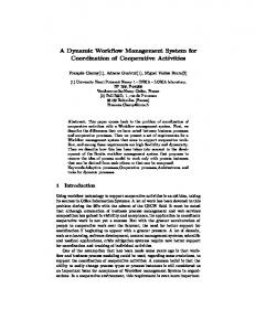
The figure shows the structure consists of six major parts
of the Walkthrough
System as planned.
the View Specifier, the user interface with which one drives the system. Specifier reads mouse, Polhemus, data-tablet, joystick, etc., devices.
l
l
l
Builder, model.
It The
a subsystem with which the user enters and modifies the building
the Master Model, an Ingres-based relational components in easy-to-manipulate form.
database carrying
the building’s
l
the Working Model, a specialized database constructed
for fast view generation.
l
the View Instanter,
Model and makes views
from it. The Instanter l
which encapsulates the Working drives the display devices.
the Toolbox, which contains algorithms by the other modules.
and data manipulation
routines needed
This decoupled modular structure is not the way the prototype is built today. Builder and View-Specifier are decoupled modules today; the rest is fairly monolithic. Data
Acquisition
OCTOBER 23-24.1986
13
A major part of the work associated with using a building the building into it. The database must be constructed. interactively
simulator
is getting
Then one wants to modify it
as one explores design concepts. During building
a building model many times, and most modifications few polygons out of thousands.
design, one modifies
are minor, affecting only a
Constructing a mathematical model of a building polygon-by-polygon is tedious work. The work is moreover unnatural, in that designers think in more hierarchical fashion. Much of it is redundant; a rectangular solid requires 6 parameters to be specified, but doing it polygon-by-polygon could require 72. For our running prototype, Dana Smith adapted Ousterhout’s Caesar microchip design tool for the input of building parameters. [Ousterhout, 19811 The Caesar tool is especially designed for manipulating,
sizing, connecting,
and labeling scaled rectangles, so it
was an excellent choice for our prototype. It is crucial, if we are to make a usable system, to devise data representations and interactive data specification techniques so that specifying and maintaining a building model is made as easy and natural as the information content will inherently
allow, and so that visual feedback is promptly
Central to our concept is the use of two distinct
available.
databases, one containing
a
subset of the other’s data: l
the Master Model, an entity-attribute relational database, operated with the Ingres relational database software, designed for cleanliness of structure and ease of modification.
l
Of this, more below.
the Working Model, a specialized data structure - visibility
and rendering
parameters
containing
only, for polygons
a subset of the data as the only entities.
This is designed for speed of instancing views.
14
CHAPELHILL.NC
INTERACTIVE 3D GRAPHICS $2 “*/
Planned (Mouse
or Tablet
SecretBUiider Man-M’achine
Interface
1 1 Sliders
M
BIOX,
MacDraft, Aulocad
I Master
System
or
Model
The library database containing the building model in entity-attribute form Secret: Data format lngres
I
Structure
(May be virtual)
PS-30n “9 I insh I Macint,,.., lor PC-RI 1
1 I Mouse,
.
ISecrets:
Tablet,
wGeneral
Tool box
1
Library of algorithms and data i subroutines
I
1 I
View
lnstancer
Generates displays for all screens Secrets: Update and refresh cycles Color-table contents Display lists and buffers Screen layouts Display device characteristics I
TreeBuilder Compiles Working Model from Master Model c++
Working
Model
Data Structure (PxPt, BSP, or other) Secrets:
Intermediate Data state
formats,
t-l
asscomp
OCTOBER 23-24,1986
Sensor 1
Blox Gia2 c++
?i
Pixei-
I
@>1986WORKSHOPON Working
Model.
The Working Model is now, and will be, entirely encapsulated
by the View Instanter, structures
so that new visibility
can be substituted
algorithms
bodily for it without
with
their own data
affecting the rest of the system.
The Working Model contains a Model Compiler that upon invocation the Master Model and rebuilds
the Working
Model.
Ultimately
accesses
we would hope
to use journaled data of changes to the Master Model to allow rapid and partial modification of the Working Model. The system component Builder is envisioned as an interBuilder Subsystem. active program that gets model parameters from the user and transforms them to canonical form and places them in the Master Model. In the process it is to be doubly interactive - by interacting with the Master Model it determines inconsistencies and incompletenesses and generates prompts for the user. By invoking the View Instancer
to make dynamic views on the vector scope, it gives
visual feedback to the user. The user will work with a mouse or datatablet, from pop-up or pull-down
0.7
The Usefulness
selecting
menus and scale views of the component he is specifying.
Question
We have now the third version of Walkthrough. than an exercise in expensive toy-building their clients be shown?
So what?
Is this any more
? Can its usefulness to architects
and
We believe this to be an inescapable, central question for all advanced application research. So UNC teams have in the past undertaken degrees of formality,
to establish, with various
the usefulness of graphics systems for:
l
molecule modeling
.
object definition
l
force display
l
true 3-D display
.
multi-parameter
l
teaching numerical
by reconstruction
from medical images
study of inventory control policies methods
As to Walkthrough, we don’t know about usefulness yet. Conclusive validation of a system such as Walkthrough is very difficult. Flight simulators can be measured by testing the operational
16
behavior of pilots trained in them. No easy operational
CHAPELHILL,NC
INTERACTIVE 3D GRAPHICS
$$$ “//
test is available to us. We plan first to collect and document anecdotal and testimonial evidence from real users. Indeed, I am reluctant to do much more technical development of the system until we get such feedback. Our fifteen years of research on graphics for molecular
structure
studies has
hammered home one lesson again and again: Frequent,
close, iterative
an essential
discipline
interaction
for the system
with
real users doing
real work
is
researcher.
Direct feedback from real work helps .
aim research at concrete objectives,
l
focus research on a few objectives at a time,
l
order
.
measure
research goals, accomplishment
against extrinsic objective criteria.
We have found capturing user sessions, by computer to yield many insights and surprises.
logging and on videotape,
There is, of course, the danger of getting idiosyncratic, not generally valid, input when one works intently with a few users. Our experience encourages us to take this risk. Each time we have learned how to solve some user’s particular well, we have found generalization Hence our next activity
problem
to solving a larger set of problems to come easily.
is to find one or more architectural
enterprises whose
working designers are willing to invest hours of their time in collaborating by using our system. We clearly must undertake to make the effort worthwhile to them on a “tbday’s job” designer-client
0.8
We suspect that usefulness will first be demonstrated
basis.
for
dialogues.
Research
Questions
The Walkthrough and applicability
System encounters several research questions of wider interest
in 3-D graphics research.
1. How fast an update rate is fast enough to give the illusion of continuous motion in a raster color-graphics context? 2. Which components of visual fidelity and world-model difference to real designers and their clients:
accuracy make the most
17
OCTOBER 23-24,1986 _-
I,
1986WORKSHOPON stereopsis - (W-11 1 a cheap post-perspective
shear transformation
be satis-
factory?) lighting models, model detail (number of polygons, e.g., doorknobs,
moldings),
texturing, curved-surface
rendering,
wide angle of view?
18
CHAPELHILL.NC
INTERACTIVE 3D GRAPHICS 4* //
3. Which of the viewing and model parameters need to be smoothly
controllable,
and how? Can analog sliders with little loss be replaced by pop-up slider scales overlaid on views?
l
Can some parameters that today are analog-specifiable seriously affecting function?
l
be fixed without
l
How is the best way to specify a head turn involving no position shift?
l
Which of our dozens of switchable
display options (e.g., walls, trees, furni-
ture) are worth the trouble? 4. How can we take advantage of special properties of the class building models to simplify or speed up our computations ? Note that flight simulators take extensive advantage of the special properties of their world models [Schachter, 19831. Among these properties for buildings are: l
Most zones of a building
are permanently
l
Most polygons are rectangular.
l
Most polygons are axial, i.e., parallel to two of the axes. Within the x,y; x,z; y,z sets of axial rectangular simplified.
l
Most potentially
invisible to each other.
polygons, visibility
each of
calculation
is
visible polygons are usually hidden by a very few that are
close to the eye. l
Most polygons are members of coplanar sets.
l
Many coplanar polygons are also nested.
l
Rooms, doors, windows, furniture,
l
Furniture
is compact - building
of a furniture l
Walk-paths
l
polygons do not intersect the convex hull
piece. are continuous and can be extrapolated
1982]. In particular, l
and other elements are replicated.
most steps change polygon visibility
Outdoor scenery visible through treated as flat painted backdrops.
windows
can perhaps
Many polygons are partly defined by intersections l
l
floors extend to exterior walls interior walls extend floor-to-ceiling
OCTOBER 23-24.1986
[Shelley and Greenberg, only slightly. be satisfactorily
with others:
or floor-to-adjacent-floor.
".,' " I, ..C?.&.?"..