Journal of Applied Science and Engineering, Vol. 15, No. 1, pp. 79-88 (2012)
79
Watermarking-Based Image Inpainting Using Halftoning Technique Kuo-Ming Hung1*, Ching-Tang Hsieh2, Cheng-Hsiang Yeh2 and Li-Ming Chen1 1
Department of Information Management, Kainan University, Taoyuan, Taiwan 338, R.O.C. 2 Department of Electrical Engineering, Tamkang University, Tamsui, Taiwan 251, R.O.C.
Abstract This study proposes a novel image inpainting technique based on watermarking and halftoning. The LSB method is used to embed error diffusion halftone image into original image for protecting the image. In image repair process, we use LSB method to extract the halftone information, and the reference image is achieved from LUT inverse halftone. Finally, the reference image is used to finish the image inpainting work. Experimental results show the performance of our method is very excellent in image inpainting. Key Words: Watermark, Inpainting, Halftone Image, Inverse Halftoning
1. Introduction Along with the gradual development of science and technology, large numbers of multi-media products get into the human’s daily life. The image information stored in a media will be damaged due to bad storing media environment or careless use by the user. Image inpainting technique aims to fill in the damaged region of an image with new information so that it is hard to find that the image has once been damaged. The technique can be used in image restoration, (e.g., scratch removal), zooming, image coding, wireless image transmission (e.g., recovering lost blocks), and special effects (e.g., removal of objects) [1]. In recent years, this technology has received extensive attention, and researchers have developed some different theories and techniques to deal with this complex image processing task. Although several early image inpainting methods have been proposed in space dimension to repair the damaged image including Partial Differential Equations (PDE) [2], fast image inpainting [3], and radial basis inpainting [4], these inpainting methods are implemented directly and simply. However, this kind of algorithm is applicable to repair *Corresponding author. E-mail:
[email protected]
narrow damaged regions in images like scratches, smuts and letters, but may produce very obvious faintness while dealing with large damaged regions. The main reason is that the image includes different frequency components at the same dimension for a single layer analysis. It will provide bad results if the inpainting decision algorithm depends on the complex components. In order to reduce the complexity degree of reconstruction and increase the relation of similarity texture, many researchers transform the image from spatial domain to frequency domain or multi-resolution domain so that the repaired results can be improved by enhancing the diversity of information analysis [5-7]. For the multi-resolution domain, wavelet transform decomposes the complex texture components into different directive sub-bands in different frequency layers. Therefore, the image complexity will be reduced in each sub-band of the decomposed image and the similarity relationship of the image components will be better, leading to a better inpainting work. But they still need sufficient data to analyze for image inpainting. In the wavelet transform, the repaired result is still good to the image with dot points, but it is unsatisfactory to the line image signals with high-frequency composition [8,9]. Hung et al. [10] proposed an inpainting algorithm based on bandelet trans-
80
Kuo-Ming Hung et al.
form, which utilizes the geometrical flow of the neighboring texture of the damaged regions as the basis of restoration. And it transforms the textural variation into the nearing domain axis utilizing the bandelet decomposition method to decompose the non-relative textures into different bands, and then combines with the affine search method to perform image restoration. However, these methods above even can be achieved good results in a certain type of image, but that cannot suit to each case and cannot work well while dealing the large damaged regions including important independent features. Therefore, we proposed a novel image inpainting technique based on data hiding and inverse halftoning which can work well suited to each case and can repair large damaged image. The LSB method is used to embed error diffusion halftone image into original image for protecting the image. In image repair process, we use LSB method to extract the halftone information, and the reference image is achieved from LUT inverse halftone. Finally, the reference image is used to finish the image inpainting work. Experiment shows the performance of our method is very excellent in image inpainting, especially applied in lossless compress transmission environment. The remainder of this chapter is organized as follows: The related works is described in section 2. Section 3 refers to our proposed method. Section 4 reports the experimental results and evaluation. Section 5 is our conclusion and future work.
2. Related Works The merit of inpainting algorithm cannot be easily detected when the repaired district is very small. For larger damaged district inpainting algorithm will determine the quality of repaired result in image contour from the viewpoint of human visual system (HVS) [11,12]. Thus, in order to improve the defects, many researchers have proposed different progressive image repairing rules. In general, the rough contours of image are repaired first and then process the local fine texture regions. They take the neighboring blocks of damaged data as effective reference data. When pixel loss increase, a large amount of both global and local reference data will be also lost, then it may lead to bad repairing results. Therefore, this study proposes a novel method to prevent such incorrect inpainting by considering three steps: one is estimating geometric flow to indicate the image contour or the rough flow of texture. The other is using
bandelet transform as analysis method to reduce the complexity of neighboring blocks of damaged data and to improve the quality of repairing results. Finally, the pixels are refilled considers the affine matching method to searching similar texture as repairing references.
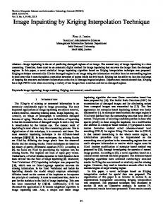
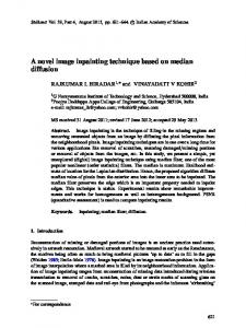
2.1 Geometric Flow Traditional image inpainting methods used highly reliable neighboring image data as the basis to repair image. If these reliable information are insufficient then the repairing results will produce wrong inpainting, as shown in Figure 1. The problem with incorrect repairing method is particularly obvious when the image is complex. In order to solve this problem, many researchers proposed multiple-scale analysis algorithm which can decompose complex images into hierarchies with different compositions. Thus, in each hierarchy the local (high-frequency data) and global (low-frequency data) reference data of images can be simultaneously considered and also maintain the correlation of each hierarchy. Such as wavelet pyramid [13] and Laplacian Pyramid [14], and Gaussian Pyramid [15], features are analyzed to avoid the repaired error to be detected from global geometry viewpoint to local geometry. Hence, better repairing result can be achieved in HVS. Errors that are resulted from neglecting the global image geometry (low-frequency composition) are the main factor of affecting the inpainting result of large damaged regions, as shown in Figure 2. In order to obtain the correct prediction for the inpainting in the rough contour of an image, establishing the geometric flow as the repairing reference is an important technique. Each image has its geometrical regular edges. Although the edges have different variations, the variations are still regular. The contour features can be represented by geometric flow. In a region W, let f (x1, x2) is the funcr tion of W. A geometric flow is a vector field t( x 1 , x 2 ) which gives a direction in which function f has regular variations in the neighborhood of each (x1, x2) Î W. To construct an orthogonal basis with a geometric flow, we shall impose that the flow is locally constant in this direction either parallel in vertical direction or parallel in horizontal direction. To simplify the explanations, we shall first consider horizontal or vertical level models [16], which are functions f that include a single edge C whose tangents have an angle with the horizontal or vertical level that remains smaller than p/3, so that C can be parameterized horizontally or vertically by a function g.
Watermarking-Based Image Inpainting Using Halftoning Technique
81
Figure 1. (a) The original image; (b) The incorrect reference information leads to the incorrect repair result.
Suppose that f is a horizontal level model. We define a vertically parallel flow whose angle with the horizontal direction is smaller than p/3. Such a flow can be written as the Eq. (1): (1) A flow line is an integral curve of the flow, whose tanr gent at (x1, x2) is collinear to t( x 1 , x 2 ). Let g(x) is a x
primitive of g¢(x) defined by g ( x ) = ò g ' ( x ) dx, that we 0
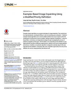
shall call flow integral. The flow lines are set of points (x1, x2) Î W which satisfy x2 = g(x1) + constant. A band B parallel to this flow is defined as follows: (2) The band height a2 and b2 are chosen so that a neighborhood of C is included in B. Geometric flow is a kind of geometric shape by describing an image with geometric vector lines. The vector lines define the local direction with regular changes in images. The decomposition of the analyzed image will obtain the parallel geometrical flow in each sub-block. In each block, the geometric flows are represented by vector field of measured direction. In the same direction of any block the geometric flow should have regular changes. If the block has no specific geometric flow, the binary system decomposition will be performed to the block. The decomposed block can be classified into three categories, which are non-geometric flow, single geometric flow, and multiple geometric flows, as shown in Figure 3.
2.2 Affine Matching In order to reconstruct the damaged pixel value, this section goes on to look at how to repair missing patches in images containing geometrical graphics. The image pixel restoration algorithm looks at how to use the effective data in the surrounding area and the inpainting deci-
Figure 2. The damaged district may be carried out to repairing direction.
sions to reconstruct the fringe values. A review of the early research papers showed that commonly used inpainting methods included extrapolation, double curve and projection. For small areas of damage and non-geometric graphics these all provided effective reconstruction pixel value estimations and good inpainting results. When these methods are applied to images containing geometric shapes, the reconstruction of missing pixels usually result in obvious repair errors because geometric shapes have a set of patterns and the human eye picks up the slightest deformations in the reconstructed image. To achieve reconstructions of geometric images that satisfy the exacting standards of human perception, this study proposed a novel repairing algorithm for lost pixels. This method uses the self-similarity of fractal geometry to strengthen the image inpainting results for geometric shapes [17-19]. In image compression and comparison applications, the fractal image processing is one of the more effective methods. This method carries out image compression using similar blocks in the image and substitutes the comparison value for the original image pixel value. This
Figure 3. The image is divided into three categories: nongeometric flow, single geometric flow, and multiple geometric flows.
82
Kuo-Ming Hung et al.
reduces the amount of redundancy in the image data and realizes the ultimate goal of increasing the image compression rate. For image comparison applications, this processing technique can quickly compare different locations within the same image to find the most similar block and achieve the optimal similarity image comparison. The central concept is that in natural images similar image information can always be found in different parts of the same image. When part of the geometric blocks within the image are damaged or lost, fractal geometry similarity comparison can be used with the available geometric information to find the most similar geometric graphics in the same image. The information from the identified image block can then be used as a basis for image inpainting. The image self-similarity search method seeks to find most similar block within the same image. The target partition R (range blocks) consists of range blocks within damaged area and search partition D (domain blocks) consists of domain blocks within undamaged area of image. We then calculate the similarity between the domain blocks and range blocks. The self-similarity conversion uses the following Eq. (3) to transform the domain blocks in search partition D. (3) In this function, the contrasting self-affinity reflection operation w is made up of two subsets [17] -contrast scaling s and luminance shift o, and x i' , yi' denote the location of domain block in the image. To find the block that matches the range block in target partition R, this study used the mean squared error measurement to calculate the similarity between range blocks and transformed domain blocks. That is (4) where xi, yi denote the location of range block. Each domain block is transformed by adjusting the contrast scaling factor S and luminance O such that its corresponding similarity reaches minimum domain block will have corresponding smallest similarity. When a domain block has the smallest similarity among all domain blocks, it means that the block is the closest match to the range block in the damaged area. Based on this mechanism the image data in the target partition R can be used to inpaint the pixel values of damaged area and complete the image reconstruction process.
3. Proposed Methods This study proposed a novel image inpainting algorithm which combines the related techniques about watermarking, halftoning and inverse halftoning. Because of self-embedding the halftone image of the cover image, we can recover the cover image from different types of damages.
3.1 Least Significant Bit Substitution The rapid development of multimedia content in digital form has escalated the necessity to build secure methods for legal distribution of the digital content. Watermarking has been considered for many copy prevention and copyright protection applications. Watermarking is the practice of hiding a message about an image, audio chip or meaningful logo within that work itself for protecting copyright. The most straight-forward method of watermark embedding would be to embed the watermark into the least-significant-bits of the cover object. LSB modification proves to be a simple and fairly powerful tool for stenography, however lacks the basic robustness that watermarking applications require. The message capacity of LSB embedding however is quite good, a 1:1 correlation with the size of the image. 3.2 Error Diffusion Algorithm for Halftoning Digital halftoning converts multi-tone image into two-tone format, and is commonly employed in newspapers, books, magazines, and computer printouts. Halftone images contain only 2 tones and are generated by a procedure called halftoning from multi-tone images. There are several kinds of published halftoning methods, including order dithering, error diffusion, dot diffusion, and least square error, and the common digital halftoning methods can be divided into two categories: ordered dithering and error diffusion [20]. The error diffusion algorithm, first introduced by Floyd and Steinberg in 1975 [21], requires neighborhood operations and is thus more computationally intensive. It is currently the most popular neighborhood halftoning process, and a generic form of this algorithm is graphically illustrated in Figure 4. (5)
(6)
Watermarking-Based Image Inpainting Using Halftoning Technique
Figure 4. The error diffusion algorithm.
(7) where I(x, y) is the input continuous-tone image at position (x, y); h is the error filter; Q is the threshold function; e(x, y) is the quantization error at position (x, y). R is the support region of the error filter coefficients; H(×) is the halftone image. The threshold t is fixed at 128 where the resulting binary output value of 0 or 255 is compared with the original gray level value. The difference is suitable called the error that the past error value is passed through an error filter to produce a correction factor to be added to future input values. The error diffusion filter suggested by Floyd and Steinberg is shown in Figure 5(a). A filter with four elements being the smallest number that could produce good results was argued. Jarvis [22] and Stucli [23] both reported as error filter with 12 elements shown in Figures 5(b) and (c) separately. The effects of error diffusion with this error filters are found to be quite similar to the host images. The error diffusion method obtains a higher quality but has high computational complexity.
3.3 Look-Up-Table Inverse Halftoning Inverse halftoning is the process of retrieving a
Figure 5. Error filters of different error diffusion methods.
83
gray-scale image from a given halftone. This has a wide range of applications such as compression, printed image processing, scaling, and enhancement. In these applications, operations cannot be done on the halftone image directly so that inverse halftoning is mandatory. Many good studies in inverse halftoning have been available in the literature, such as Gaussian Filtering [24], Nonlinear Filtering [25], Wavelet-Based technique [26,27], Shape-Adaptive DCT [28], Look-Up-Table (LUT) [29] and Edge-Based Lookup Table (ELUT) [30]. We adopt LUT algorithm for inverse halftoning because it is general and practical. We describe LUT algorithm as follow: A Look-Up-Table (LUT) based algorithm proposed by Mese and Vaidyanathan [29] produces very good results with low computational complexity. However, the LUT method uses the mean of corresponding contone values of existent binary input patterns to predict the contone value of non-existent binary input patterns. In other words, the LUT method creates the reconstructive function according to the training images. The first step is to choose the neighborhood or template for the pixels to be used in the prediction. Author used two different templates as shown in Figure 6. In Figure 6(a), a rectangular template is shown, and this template is abbreviated as “Rect” in comparison tables later. “O” denotes the estimated pixel. All of the pixels are used in the prediction. In Figure 6(b) another template is shown. This pattern consists of a symmetric part and some additional pixels. In the 16-pixel pattern the “a” pixels and the “O” pixel are used in the prediction of the contone value of pixel “O”. This template is denoted as “16 pels” in comparison tables. Another example of a template is obtained by adding “b” pixels to the “16 pels” template and this template is referred to as “19 pels” template. Authors assume that there are pixels (including the pixel being estimated) in the neighborhood and that they are ordered in a specific way. They call the pixel values
Figure 6. LUT template [29].
84
Kuo-Ming Hung et al.
as p0, p1, …, pN-1. Where pi Î {0, 1} for i = 0, 1, …, N - 1. Note that there are 2N different patterns since for i = 0, 1, …, N - 1. If the original image is an 8 bit gray image, LUT should return a value for each pattern, i.e., T(p0, p1, …, pN-1) Î {0, 1, …, 255}. During the inverse halftoning phase, the pixels in the template will be arranged in a specific order, and the contone value will be obtained from the LUT. The design of LUT describe as follows: author first obtained the expected contone value for each template pattern. Then this contone value would be assigned to the corresponding LUT position for that pattern. They denoted the number of occurrences of pattern (p0, p1, …, pN-1) in the sample halftone images as K(p0, p1, …, pN-1). Thus, K(p0, p1, …, pN-1) is the histogram value of the pattern (p0, p1, …, pN-1). They denoted the contone values in the original images corresponding to patterns (p0, p1, …, pN-1) as C(p0, p1, …, pN-1), for i = 0, 1, …, K(p0, p1, …, pN-1) - 1. If, K(p0, p1, …, pN-1) > 0, the LUT value for the pattern would be the mean of the corresponding contone values, i.e.
(8)
If K(p0, p1, …, pN-1) = 0, then the pattern (p0, p1, …, pN-1) does not exist. The contone values for nonexistent patterns should be estimated from the existent patterns. The best linear estimator was proposed for nonexistent
pattern estimation [29]. In this method, a linear model is used to estimate the contone values in terms of halftone values inside the template.
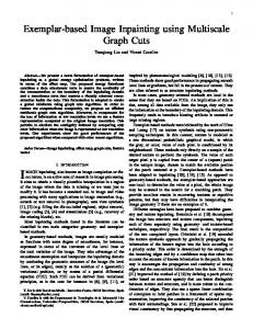
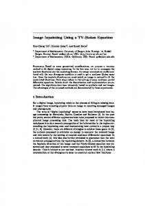
3.4 Proposed Image Inpainting System The proposed image inpainting system was divided into two phases: watermark embedded phase and inpainting phase. In watermark embedded phase, we first converts original image into halftone image with halftoning algorithm. Then we permute the halftone image in order to increase the robustness to local attacks. Finally, we embed the permuted random binary image into the original image with Least Significant Bit Substitution method. The process of watermark embedded phase is shown as Figure 7. In inpainting phase, we first extract the random binary damaged image from the damaged image with least significant bit substitution method, and then repermute the random binary damaged image to obtain the damaged halftone image, and convert the damaged halftone image to the reference image with inverse halftoning algorithm. Finally, after enhancing reference image with median filter, we substitute the pixels of attacked area in damaged image with the enhanced reference image in the same position. The process of inpainting phase is shown as Figure 8.
4. Experimental Results The process of proposed image inpainting system is
Figure 7. The process of watermark embedded phase.
Figure 8. The process of inpainting phase.
Watermarking-Based Image Inpainting Using Halftoning Technique
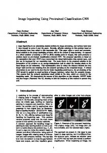
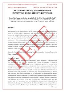
divided into two phases: watermark embedded phase and inpainting phase. There are three steps in watermark embedded phase as follows: Step 1: Converts original image into halftone image. Step 2: Permute the halftone image. Step 3: Embed the permuted random binary image into the original image with LSB method. In our experiment, we converts original image into halftone image with error diffusion algorithm, because of the performance of error diffusion algorithm is better than order dithering. We permute the halftone in order to increase the robustness against local attacks. For the good results of imperceptibility and capacity, we adopt LSB method for data embedding. Figure 9 is the process and result in watermark embedded phase for Lena. Figure 9(a) is the original image Lena (512 ´ 512). Figure 9(b) is the halftone image converted from Figure 9(a) with error diffusion method. Figure 9(c) is the permuted binary random image converted form Figure 9(b). Figure 9(d) is the protected image which is embedded Figure 9(c) into Figure 9(a). In watermark embedded phase, we compare the protected image (Figure 9(d)) with original image (Figure 9(a)), they are difficultly distinguished with human visual system. The PSNR of the protected image (Figure 9(d)) to (Figure 9(a)) is 54.14 db. In inpainting phase, there are five steps as follow: Step 1: Extract the random binary damaged image from the damaged image with LSB method. Step 2: Repermute the random binary damaged image to obtain the damaged halftone image. Step 3: Convert the damaged halftone image to the reference image with LUT inverse halftoning algorithm. Step 4: Enhance the reference image with median filter. Step 5: Substitute the pixels of attacked area in damaged image with the enhanced reference image in the same position. We adopt LUT algorithm for inverse halftoning because it is general and practical. Figure 10 is an example of inpainting phase. Figure 10(a) is the damaged Lena image attacked in both eyes. Because the both eyes are the important independent features, there could not be found similar reference areas or textures in the neighborhood within the image. Other published inpainting algorithms cannot work well while dealing the large damaged regions including important independent features
85
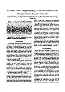
like Figure 10(a). Figure 10(b) shows the random binary damaged image extracted from the damaged image (Figure 10(a)) with LSB method. Figure 10(c) shows the damaged halftone image converted from the random binary damaged image Figure 10(b). Figure 10(d) shows the reference image converted from the damaged halftone image (Figure 10(c)) with LUT inverse halftoning algorithm. Figure 10(d) the reference image converted from the reference image Figure 10(c) with LUT inverse halftoning algorithm. Figure 10(e) shows the enhanced reference image form the reference image Figure 10(d) with median filtering. The restored image is shown as Figure 10(f), and the PSNR to original image is 48.82. This experiment shows the performance of the proposed algorithm is very excellent. We also test the results of inpainting for different damaged rate as shown in Figures 11-17. Even if the damaged rate is 64.83%, we still can distinguish the content of the image. Finally, we use the common image “Barbara” as the test image for inpainting. This test mainly focuses on the texture part of image, because this type of damaged regions cannot be repaired well using the current image inpainting methods. In Figure18(b), we can easily find the errors of the repairing result using the PDE method. However, based on Figures 18(c) and (d), which are im-
Figure 9. Watermark embedded phase (a) Original image Lena (512 ´ 512); (b) The halftone image converted from (a) with error diffusion method; (c) The permuted binary random image converted form (b); (d) the protected image which is embedded (c) into (a), PSNR = 54.14.
86
Kuo-Ming Hung et al.
plemented by PII [7] method and our proposed method, respectively, it’s hard to distinguish the difference in vi-
sual. We use the zoom-in images to compare these two repairing results, which are shown in Figures 19 (b) and
Figure 12. (a) Damaged rate is 1.35% for Lena; (b) Restored image, PSNR = 48.82.
Figure 13. (a) Damaged rate is 2.09% for Lena; (b) Restored image, PSNR = 47.25.
Figure 10. An example of inpainting phase (a) The damaged Lena image attacked in both eyes from the protected image (Figure 9(d)); (b) The random binary damaged image from (a) with LSB method; (c) The damaged halftone image converted from (b); (d) The reference image converted from (c) with LUT inverse halftoning algorithm; (e) The enhanced reference image form (d) with median filtering; (f) The restored image.
Figure 14. (a) Damaged rate is 5.46% for Lena; (b) Restored image, PSNR = 41.12.
Figure 11. (a) Damaged rate is 1.76% for Lena; (b) Restored image, PSNR = 47.80.
Figure 15. (a) Damaged rate is 10.74% for Lena; (b) Restored image, PSNR = 34.17.
Watermarking-Based Image Inpainting Using Halftoning Technique
87
Figure 16. (a) Damaged rate is 41.07% for Lena; (b) Restored image, PSNR = 16.69.
Figure 18. Experimental results from utilizing different methods: (a) The damaged image; (b) The PDE method [2]; (c) The PII method [7]; (d) Our proposed method. Figure 17. (a) Damaged rate is 64.85% for Lena; (b) Restored image, PSNR = 10.69.
(c). We can clearly find that the repairing result of our proposed method is more precise than that of PII method in texture variation. Figures 18 and 19 show that the proposed method is better than others.
5. Conclusion and Future Work This study proposes a novel image inpainting techniques which integrate algorithms of halftoning, inverse halftoning and watermarking. The LSB method is used to embed error diffusion halftone image into original image for protecting the image. In image repair process, we use LSB method to extract the halftone information, and the reference image is achieved from LUT inverse halftone. Finally, the reference image is used to finish the image inpainting work. Experimental results show the performance of our method is very excellent in image inpainting. Because of using LSB method to embed halftone data, our proposed system can only be applied in lossless compression transmission environment. In future, we will modify the embedded method to enable our system to be possible applied under loss and lossless environments.
References [1] Shih, T. K. and Chang, R. C., “Digital Inpainting —
Figure 19. Zoom-in inpainting result of Figures 18(a), (c) and (d): (a) The damaged region; (b) The PII method [7]; (c) The proposed method.
Survey and Multilayer Image Inpainting Algorithms,” Proc. IEEE Int. Conf. Inform. Tech. Appl., Vol. 1, pp. 15-24 (2005). [2] Bertalmio, M., Sapiro, G., Caselles, V. and Ballester, C., “Image Inpainting,” SIGGRAPH, pp. 417-424 (2000). [3] Telea, A., “An Image Inpainting Technique Based on the Fast Marching Method,” Journal of Graphics Tools, Vol. 9, ACM Press, pp. 25-36 (2004). [4] Zhou, T., Tang, F., Wang, J., Wang, Z. and Peng, Q., “Digital Image Inpainting with Radial Basis Functions,” J. Image Graphics, pp. 1190-1196 (2004). [5] Liew, A. W. C., Law, N. F. and Nguyen, D. T., “Multiple Resolution Image Restoration,” IEE Proceedings Vision, Image and Signal Processing, Vol. 144, pp. 199-206 (1997). [6] Burrus, C. S., Gopinath, R. A. and Guo, H., Introduc-
88
Kuo-Ming Hung et al.
tion to Wavelets and Wavelet Transform, Prentice-Hall (1998). [7] Chen, Y. L., Hsieh, C. T. and Hsu, C. H., “Progressive Image Inpainting Based on Wavelet Transform,” IEICE, Trans. Fund., Vol. E88-A, pp. 2826-2834 (2005). [8] Le Pennec, E. and Mallat, S., “Sparse Geometrical Image Representation with Bandelets,” IEEE Trans. Image Process, Vol. 14, pp. 423-438 (2005). [9] Le Pennec, E. and Mallat, S., “Bandelet Image Approximation and Compression,” SIAM J. Multiscale Simul., Vol. 4, pp. 992-1039 (2005). [10] Hung, K. M., Chen, Y. L. and Hsieh, C. T. “A Novel Bandelet-Based Image Inpainting,” IEICE TRANSACTIONS on Fundamentals of Electronics, Communications and Computer Sciences, Vol. E92-A, pp. 24712478 (2009). (SCI) [11] Grattoni, P., Pollastri, E. and Premoli, A., “A Contour Detection Algorithm Based on the Minimum Radial Inertia (MRI) Criterion,” CVGIP, Vol. 43, pp. 22-36 (1988). [12] Eslami, R. and Radha, H., “Wavelet-Based Contourlet Transform and Its Application to Image Coding,” IEEE Intl. Conf. on Image Processing, pp. 3189-3192 (2004). [13] Olshausen, B. A., Sallee, P. and Lewicki, M. S., “Learning Sparse Image Codes Using a Wavelet Pyramid Architecture,” Advances in Neural Information Processing Systems 13, MIT Press: Cambridge, MA, pp. 887893 (2000). [14] Burt, P. J. and Adelson, E. H., “The Laplacian Pyramid as a Compact Image Code,” IEEE Trans. Commun., Vol. 31, pp. 532-540 (1983). [15] Adelson, E. H., Anderson, C. H., Bergen, J. R., Burt, P. J., Ogden, J. M., “Pyramid Methods in Image Processing,” RCA Engineer, Vol.29, pp. 33-41 (1984). [16] Donoho, D., “Wedgelets: Nearly-Minimax Estimation of Edges,” Ann. Statist., Vol. 27, pp. 353-382 (1999). [17] Belloulate, K. and Konard, J., “Fractal Image Compression with Region-Based Functionality,” IEEE Trans on Image Proc., Vol. 2, pp. 345-350 (2002). [18] Fisher, Y., Fractal Image Compression, SpringerVerlag, New York (1995). [19] El Rube, I. A., Ahmed, M., Kamel, M., “Coarse-toFine Multiscale Affine Invariant Shape Matching and Classification,” Proceedings of the Pattern Recogni-
tion, 17th International Conference on (ICPR’04), Vol. 2, pp. 163-166 (2004). [20] Ulichney, R., Digital Halftoning, The MIT Press (1987). [21] Floyd, R. W. and Steinberg, L., “Adaptive Algorithm for Spatial Grey Scale,” SID Int. Sym. Digest of Tech. Papers, pp. 36-37 (1975). [22] Javis, J. F., Judice, C. N. and Ninke, W. H., “A Survey of Techniques for the Display of Continuous-Tone Pictures on Bilevel Displays,” Computer Graphics and Image Processing, Vol. 5, pp. 13-40 (1976). [23] Stucki, P., “MECCA - A Multiple Error Correcting Computation Algorithm for Bilevel Image Hardcopy Reproduction,” Research Report RZ1060, IBM Research Laboratory (1981). [24] Hein, S. and Zakhor, A., “Halftone to ContinuousTone Conversion of Error-Diffusion Coded Image,” IEEE Trans. Image Processing, Vol. 4, pp. 208-216 (1995). [25] Shen, M. Y. and Kuo, C.-C. J., “A Robust Nonlinear Filtering Approach to Inverse Halftoning,” J. Vis. Commun. Image Represen., Vol. 12, pp. 84-95 (2001). [26] Neelamani, R., Nowak, R. and Baraniuk, R., “WinHD: Wavelet-Based Inverse Halftoning via Deconvolution,” IEEE Trans. on Image Process., October 2002. Submitted. [27] Xiong, Z., Orchard, M. T. and Ramchandran, K., “Inverse Halftoning Using Wavelets,” IEEE Trans. Image Process., Vol. 8, pp. 1479-1482 (1999). [28] Dabov, K., Foi, A., Katkovnik, V. and Egiazarian, K., “Inverse Halftoning by Pointwise Shape-Adaptive DCT Regularized Deconvolution,” Proc. 2006 Int. TICSP Workshop Spectral Meth. Multirate Signal Process., SMMSP 2006, Florence (2006). [29] Mese, M. and Vaidyanathan, P. P., “Look Up Table (LUT) Method for Inverse Halftoning,” IEEE Trans. Image Process., Vol. 10, pp. 1566-1578 (2001). [30] Chung, K.-L. and Wu, S.-T., “Inverse Halftoning Algorithm Using Edge-Based Lookup Table Approach,” IEEE Trans. on Image Process., Vol. 14, pp. 15831589 (2005).
Manuscript Received: Oct. 26, 2010 Accepted: Apr. 29, 2011