764
JILIANG ZHANG, ET AL., WATERMARKING FPGA BITFILE FOR INTELLECTUAL PROPERTY PROTECTION
Watermarking FPGA Bitfile for Intellectual Property Protection Jiliang ZHANG, Yaping LIN, Qiang WU, Wenjie CHE College of Information Science and Engineering, Hunan Univ., No. 252, Lushan South Road, Changsha, 410082, China
[email protected],
[email protected],
[email protected],
[email protected] Abstract. Intellectual property protection (IPP) of hardware designs is the most important requirement for many Field Programmable Gate Array (FPGA) intellectual property (IP) vendors. Digital watermarking has become an innovative technology for IPP in recent years. Existing watermarking techniques have successfully embedded watermark into IP cores. However, many of these techniques share two specific weaknesses: 1) They have extra overhead, and are likely to degrade performance of design; 2) vulnerability to removing attacks. We propose a novel watermarking technique to watermark FPGA bitfile for addressing these weaknesses. Experimental results and analysis show that the proposed technique incurs zero overhead and it is robust against removing attacks.
Keywords Field programmable gate array (FPGA), intellectual property protection (IPP), watermarking.
1. Introduction The advance in semiconductor processing technology has led to rapid increase in integrated-circuit (IC) design complexity. Reuse-based design methodology has prevailed in IC design field. Intellectual property (IP) reuse can reduce product costs, shorten design cycles and decrease the design risk. Nowadays, reusable IP cores have become the basic units of system design. IP cores are widely exchanged and are being sold as an independent design. Most of reusable IP cores require a lot of time and effort to be implemented and verified by IP vendors, but these IP cores can be very easily copied or modified. Therefore, IP vendors are eager in keeping their products protective from unauthorized using and tampering. Additionally, users also expect that purchased IP core is correct and legitimate. How to protect reusable IP cores effectively has become a serious problem and therefore an increasing amount of attention has been paid. Various kinds of IPP techniques, such as watermarking, fingerprinting, are proposed by researchers both from the industry and the academia. Among these techniques, watermarking is the most extensive mechanism imple-
mented in the abstraction levels of IC design flow to protect IP cores from illegal reuse. The concept of digital watermarking FPGA is first proposed by Lach et al. [5]. The basic idea is that the owner's digital signature is embedded into unused (look-up tables) LUTs in unused slices (i.e. non-functional slices) at physical layout level. The constrained Configurable Logic Blocks (CLBs) are then incorporated into the design with unused interconnect and “don’t care” inputs of neighboring CLBs, which then consecutively further hides the signature. Since watermark is randomly embedded into unused slices, this method inevitably generates extra area overhead, and neighboring CLB “don’t care” inputs that are used to connect watermarked slices will incur timing overhead to a certain extent. The watermark is vulnerable to (partial) removing attacks. Later, the author improved the robustness to a certain extent using multiple small watermarks [6]. The experimental results report resource overhead varying from 0.05% to 33.86% and timing overhead from –25.93% to 11.95%. Additionally, no attention has been paid on probability of coincidence (Pc) and power overhead due to watermarking. Kahng et al. [7] first proposed the notion of constraint-based watermarking. The idea is as follows. Firstly, in order to make use of a number of satisfiability (SAT) issues during IP development process, the constraint generator transforms embedded watermark into a set of additional constraints, then limits the solution of the SAT problem into a smaller space when they are added to the constraints. Finally, a unique design is generated with a watermark. The constraint-based method has been used to develop many watermarking schemes for IPP at different abstraction levels of VLSI/FPGA design flow [8-13]. However, additional constraints of these methods if imposed would consecutively bring extra overhead to the design. A zero-cost method of watermark embedding was proposed by Adarsh K. Jain et al. [15]. The method mainly modifies the non-critical path delay between non-synchronous registers to embed the watermark in the placement and routing stage. The proposed watermark scheme doesn’t need additional hardware resources. Therefore its area and delay overheads are almost zero. However, because the changing part is the path delay, the performance of design would be affected to a certain extent. Additionally, authorship verifiability is a fatal weakness, since the watermark cannot be verified at lower abstract level of IC design flow. The
RADIOENGINEERING, VOL. 21, NO. 2, JUNE 2012
watermarking technique cannot be applicable if lack of traceability. D. Ziener et al. [16] introduce a method to identify IP cores in an FPGA by analyzing the content of LUTs. This technique can be used to identify registered cores for IP protection against unlicensed usage, but the extraction of content of the LUT from a configuration bitfile excessively depends on FPGA device and FPGA vendor. M. Schmid et al. proposed a netlist-level IPP scheme [17], which modifies LUTs of netlist-level and converts functional LUTs to LUT-based RAMs or shift registers to prevent deletion due to optimization. But the overhead incurred is large. After an analysis of the public domain core: Cordic, the scheme showed resource overhead ranged from 4.97% to 52.57% and timing overhead from 32.53% to 78.76% at a fixed interconnection length of 4. Finite state machine (FSM) watermarking [10], [14], [21] is another kind of method that can be applied to FPGA design for IPP. FSM watermarking embeds the signature at behavioral/RT level of design abstraction. Although ownership can be authenticated directly, it is challenging to keep the overhead of watermarked design low [1] and it does not permit ownership to be detected directly after IP cores have been packaged except the literature [1]. Lots of watermarking techniques have been proposed. However, there are two key weaknesses for existing IP watermarking techniques. Firstly, many of these techniques incur extra overhead (area, timing or power overhead). However, area, timing and power are key optimization goals of FPGA design [2]. Watermarking hardware IP demands that the watermarked IP maintains the correctness of functionality while keeping the performance and cost overheads as low as possible [3]. Secondly, existing watermarking techniques can successfully embed watermark into IP cores, but they have the vulnerability to watermark removal. In this paper, we propose a novel watermark technique that can achieve the goals of zero-overhead without affecting the function and performance of design. Additionally, it has the ability of resisting to removing attacks. There are many functional slices containing lots of LUTs that have not been used effectively. This kind of LUTs, we call as “ILUT”. Firstly, we acquire a set of ILUT at post layout of FPGA design flow. Secondly, the locations where encrypted watermarks need to be embedded into are determined by a pseudo random sequence. Thirdly, Encrypted watermark is grouped using Content-Copy Method (CCM), and then inserted into ILUTs. Finally, an interconnection method applies to interconnection between embedded watermark LUTs and the adjacent functional LUTs to disguise the embedded watermark. Our watermarking method has several merits in comparison with related watermarking techniques: 1) zerooverhead: zero area, timing and power overhead; 2) having no impact on the function and performance of design; 3) The watermark is grouped by using CCM, which makes the content feature of the watermarked ILUTs be identical to functional LUTs. Hence, the embedded watermark is very difficult to be detected and removed; 4) the proposed
765
watermarking scheme has a very low probability of coincidence and hence provides strong proof of authorship. 5) The position of the watermark inserted is determined by a pseudo-random sequence, so watermarking verification process is executed easily; 6) the proposed watermarking technique is zero-overhead, so it can blend well with existing watermarking techniques for the IPP to augment the ownership detectability and traceability.
2. The Proposed Watermarking Technique 2.1 Watermarking Principle The CLBs are the main logic resources of FPGA for implementing sequential as well as combinational circuits. A CLB element in Virtex-5 FPGAs contains a pair of slices. Each slice contains four 64×1 LUTs (or 32×2 LUTs) and four flip-flops. The function generators are implemented as six-input LUTs. There are six independent inputs and two independent outputs for each of the four function generators in a slice. The function generators can implement any arbitrarily defined six-input Boolean function [18]. In other words, you can configure the LUTs to implement any Boolean function. The logic functions that the slices implemented are classified into three categories after placement and route phase: 1) Combinational with register. The slices are used to implement the combinational logic and sequential logic. 2) Register only. These slices are only used to implement sequential logic. Flip-flops of these slices are used, but the LUTs are not used. 3) Combinational with no register. These slices are only used to implement the combinational logic. The number and utilization factor of the three kinds of slices can be obtained from Device Utilization Summary (Xilinx FPGAs) or Fitter Resource Usage Summary (Altera FPGAs). All of the three kinds of already used slices may contain some LUTs, which have not been used effectively. We called this kind of LUTs as “ILUTs”. ILUTs have a key feature: they consist in functional slices and actually have been used by FPGA designs, except that these ILUTs have no function. All the cells content of a 6-input ILUT are set to ‘1’. These ILUTs have been reported "used" in the Place and Route Report, which is generated by Xilinx ISE tool. The reasons why ILUTs exist in FPGA designs are related to placement and routing. Simply adding interconnects to achieve high LUT utilization is not always area efficient [19]. Since interconnection resources consume most of the area on FPGA devices (often 80-90%), we can achieve more area efficient designs by allowing some LUT to go unused — allowing us to use the domain resource, interconnect, more efficiently [19]. Therefore, there are lots of ILUTs in FPGA designs. The experimental result (see Tab. 1) also shows that the number of ILUT is large.
766
JILIANG ZHANG, ET AL., WATERMARKING FPGA BITFILE FOR INTELLECTUAL PROPERTY PROTECTION
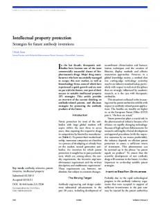
After placement and routing, we acquire the set of ILUTs, and then we employ the editing tool FPGA Editor to configure ILUTs to embed the watermark. A 6-input ILUT can be considered as a RAM and can store up to 64bit digital marks, with a 6-bit inputs specifying the address of the bit to read from the stored mark. For instance, assume a 4-bit marks w = “0110”, which can be implemented with a Boolean function F (A1, A2, A3, A4, A5, A6) = A1 or A2. A1 and A2 are inputs that are randomly selected from A1~A6. F can be configured into an ILUT by the FPGA Editor; the output of the ILUT is w. Fig. 1 shows that the watermark w is embedded into an ILUT.
Fig. 1. An example of implementing a function F in an ILUT.
2.2 The Proposed Content-Copy Method All LUTs of an FPGA have n inputs. There are lots of m used input LUTs in B, m < n. m-input LUTs must be mapped into n-input LUTs. If one input is unused, only half of the memory is needed to store the function and the remaining space must be filled [16]. This depends on FPGA architecture. If the output of an ILUT is routed to the input of an n-input LUT, the content of an (n-1)-input LUT is copied into the unused region of the n-input LUT, no matter the unused input is applied one or zero, the output of the LUT is correct (This feature of FPGA is called CCM). Therefore, the functionality of LUT remains unchanged.
of the LUT cell is 000010 (001010), and the corresponding output of the LUT is 0 (0). i.e., no matter A4 is 0 or 1, the output of the LUT is 0, which is correct. In order to improve the robustness of the proposed watermarking technique, we applied the CCM to group the watermark and then embedded the grouped watermark into ILUTs. After applying the CCM, the content features of the watermarked ILUTs are the same as functional LUTs. The implement of CCM is: for an n-input ILUT, we randomly selected m inputs from n to implement function as the watermark (m n). After the watermark is embedded into the ILUTs, watermarked functional slices have connected with other slices, but there is no physical net connection between the watermarked ILUTs and the original design, an attacker may use brute-force search to find the non-interconnected LUTs with no input and output, and then empty the content of these LUTs. The watermark would be removed. An interconnection method is applied to the watermarked ILUTs to disguise the embedded watermark. Besides, the interconnection method can maintain the correctness of designs. Therefore, our watermarking method can guarantee the security of the embedded watermark without affecting the function of designs. Meanwhile, experimental results show that the proposed interconnection method incurs zero timing overhead on original FPGA design. The interconnection method is that the inputs of the watermarked ILUTs are taps off of inputs or outputs of adjacent functional LUTs, and then the outputs are routed to neighboring functional LUTs “don’t care” inputs or the watermarked ILUTs “don’t care” inputs.
2.3 The Overview of the Proposed Watermarking Technique In this paper, we employ mathematically precise approaches [17], [20] to describe our watermarking technique. The proposed watermarking technique for FPGA designs consists of watermark preparation algorithm PB, watermark embedding algorithm EB, and watermark verification algorithm VB.
Fig. 2. An example of LUT’s function remaining stable with interconnection method.
Give a simple example, a 6-input LUT is shown in Fig. 2, suppose the function of ILUT is F (A1, A2, A3, A4, A5, A6) = ~ (A1 XOR A2) (A1 and A2 are the used inputs of the LUT, and A3~A6 are “don’t care” inputs). The output of an ILUT is connected to A4 (indicated by red lines). Given A1 is 0 and A2 is 1, if A4 is 0 (1), then the address
Watermark preparation algorithm PB (WB = PB (K, S)) generates a watermark WB according to a key K and the signature S. A key K is a sequence of binary bits (K= {0, 1}n). The watermark is embedded into the design IB by the embedding algorithm EB (‘IB = EB (IB, WB, L, R)) creating a watermarked design ‘IB. R is the position where watermark will be embedded in. L = Ext (IB), L is extracted from the design IB. The verification algorithm VB (‘IB, WB) receives a watermark WB and a design ‘IB as inputs. It is capable of efficiently determining whether WB is contained in ‘IB. If WB is contained in the design ‘IB, the output of the verification algorithm is VB (‘IB, WB) = true, and if it is not, VB (‘IB, WB) = false.
RADIOENGINEERING, VOL. 21, NO. 2, JUNE 2012
767
Define the set of ILUT L= {ILUT1, ILUT2,…, ILUTn} (n = 0, 1,…). Each ILUT can accommodate up to 64bit watermark. The hashed and encrypted signature WB is divided into groups: {wB1, wB2,…,wBl}, wBi∈WB, i = 0,1,…,l. LenBi representing the length of wBi, is randomly selected from the set of {4, 8, 16, 32, 64}. wBi was embedded in the specific location where determined by the pseudo-random number sequence R (R = Random (WB) = {rB1, rB2,…, rBl}. We describe our watermarking algorithm in the flowchart shown in Fig. 3. Detailed description of our watermarking algorithm is presented in section 2.4 and 2.5.
Fig. 4. The flow of watermark preparation and watermark embedding.
The watermark preparation and embedding algorithm are shown as follows: 1. 2. 3. 4. 5. 6. 7. 8. 9. 10. Fig. 3. The overview of the proposed watermarking method.
2.4 Watermark Preparation and Embedding In order to ensure the safety of our signature, it needs to be hashed and then encrypted. First we employ a secure hash algorithm (e.g. SHA1) to generate a hash value with non-linear functions from a signature, which is denoted by h = H(S), S denotes the signature. It is computationally infeasible to find another signature that hashes to the same value. The next step is to encrypt the hashed value with the key Key1. This is implemented by a public key algorithm, e.g. RSA, which is an asymmetrical cryptographically method. To embed the watermark, we need to get information about the content of the watermark and the positions where the watermark will be embedded. The content of the watermark is generated by WB = Enckey1 (h). WB is divided into groups {wB1, wB2,…,wBl} by randomly selecting the length of wBi from the set of {4, 8, 16, 32, 64}, the length of wBi is denoted by LenBi = length(wBi). We get the information about the positions of the watermark from a pseudo random sequence, which is generated by a pseudo random generator, e.g. RC4 (WB as the seed). The pseudo random sequence is denoted by R = Random (WB) = {rB1, rB2,…,rBl }. The preparation and embedding process of the watermark is detailed in Fig. 4.
Provide the signature S; h = H(S); WB = Enckey1 (h); Divide WB into groups {wB1, wB2,…, wBl};//CCM R = Random (WB); // R = {rB1, rB2,…,rBl } L = Ext (IB); // L = {ILUT1, ILUT2,…, ILUTn} for (i = 0; i < Bl; i ++) { Build logic Functions FBi according to wBi; Configure FBi into an ILUT according to rBi; Apply the interconnection method to connect the watermarked ILUTs with the original design; 11. } 12. The watermark Embedding is done;
Watermark preparation is performed in steps 1 - 3. CCM is applied to the watermarked ILUTs in step 4. The locations of the watermark are generated in step 5. The set of ILUTs can be extracted from the design IB in step 6. Watermark embedding is then performed from step 7 - 11.
2.5 Watermark Verification When the IP vendors suspect that their IP has been infringed, they can apply for a neutral third-party organization to extract the watermark from the IP core using the following algorithm, and then the ownership of the IP core will be easily verified. The process of watermark verification is the inverse of watermark embedding.
3. Experimental Results The proposed technique has been implemented on Xilinx Virtex XC5LX50t-3ff1136 FPGA. The tested IP cores come from IWLS 2005 benchmarks [4]. The experimental results show that the proposed watermarking technique has zero overhead and very low Pc.
768
JILIANG ZHANG, ET AL., WATERMARKING FPGA BITFILE FOR INTELLECTUAL PROPERTY PROTECTION
reported "used" in the Place and Route Report, which is generated by Xilinx ISE tool. Since we embed marks into the ILUTs, our approach incurs zero area overhead. Time overhead is measured by the minimum period degradation. We use the Timing Analyzer (Xilinx tool) to analyze timing overhead. As shown in Tab. 3, minimum period is unchanged, so we claim that our method has zero timing overhead. This can be explained that we only change part of the net connection of adjacent functional LUTs and hence original design is changed slightly. Tab. 5-7 dedicate that the changes are inappreciable: only some of the “hold
3.1 Overhead Analysis Tab.1 shows that the number of ILUTs is very large for different IP cores. The length of the embedded watermark can go up to 64-bit for an ILUT. The watermark can be embedded into each ILUT. Hence, for any medium IP core it can accommodate a fairly large digital watermark. As shown in Tab. 2, resources overhead is denoted by the increased “Number of Slice LUTs”. ILUTs consist in functional slices and actually have been used in the FPGA design. Only these ILUTs have no function and have been Cores #ILUTs # watermark bits = #ILUTs*64
aes_core 481 30784
vga_lcd 841 53824
pci_bridge32 2240 143360
ethernet 1151 73664
des_perf 5752 368128
Tab. 1. The number of ILUTs and corresponding watermark bits. N.S.L.: Number of Slice LUTs Original IP Core N.S.L. aes_core 564 vga_lcd 1,007 pci_bridge32 1,453 ethernet 2,914 des_perf 5,768
W.M: Watermark 64bit W.M N.S.L. Overhead 564 0% 1,007 0% 1,453 0% 2,914 0% 5,768 0%
256bit W.M N.S.L. Overhead 564 0% 1,007 0% 1,453 0% 2,914 0% 5,768 0%
512bit W.M N.S.L. Overhead 564 0% 1,007 0% 1,453 0% 2,914 0% 5,768 0%
1024bit W.M N.S.L. Overhead 564 0% 1,007 0% 1,453 0% 2,914 0% 5,768 0%
2048bit W.M N.S.L. Overhead 564 0% 1,007 0% 1,453 0% 2,914 0% 5,768 0%
Tab. 2. Effect of number of watermarks on resources (Slice LUTs). M.P.: Minimum Period Original IP Core M.P(ns) aes_core 5.728 vga_lcd 3.747 pci_bridge32 5.576 ethernet 7.139 des_perf 2.605
64bit W.M M.P(ns) Overhead 5.728 0% 3.747 0% 5.576 0% 7.139 0% 2.605 0%
256bit W.M M.P(ns) Overhead 5.728 0% 3.747 0% 5.576 0% 7.139 0% 2.605 0%
512bit W.M M.P(ns) Overhead 5.728 0% 3.747 0% 5.576 0% 7.139 0% 2.605 0%
1024bit W.M M.P(ns) Overhead 5.728 0% 3.747 0% 5.576 0% 7.139 0% 2.605 0%
2048bit W.M M.P(ns ) Overhead 5.728 0% 3.747 0% 5.576 0% 7.139 0% 2.605 0%
Tab. 3. Effect of number of watermarks on timing (Minimum Period). P.: Power IP Core aes_core vga_lcd pci_bridge32 ethernet des_perf
Original P. (mW) 505 506 506 15 506
64bit W.M P. (mW) Overhead 505 0% 506 0% 506 0% 15 0% 506 0%
256bit W.M P. (mW) Overhead 505 0% 506 0% 506 0% 15 0% 506 0%
512bit W.M P. (mW) Overhead 505 0% 506 0% 506 0% 15 0% 506 0%
1024bit W.M P. (mW) Overhead 505 0% 506 0% 506 0% 15 0% 506 0%
2048bit W.M P. (mW) Overhead 505 0% 506 0% 506 0% 15 0% 506 0%
Tab. 4. Effect of number of watermarks on power. Source Original 1024bit W.M
text_in 1.485 1.486
text_in 0.724 0.725
text_in 1.418 1.419
text_in 0.931 0.932
text_in 1.570 1.571
text_in 1.071 1.072
text_in 0.986 0.987
text_in 1.473 1.474
text_in -0.250 -0.251
text_in -0.209 -0.210
Tab. 5. The change of hold to clock clk (IP core: aes_core). Source Original 1024bit W.M
text_in -0.237 -0.238
text_in 0.586 0.585
text_in -0.168 -0.169
text_in 0.363 0.362
text_in -0.207 -0.208
text_in 0.639 0.638
Tab. 6. The change of setup to clock clk (IP core: aes_core) Destination Original 1024bit W.M
text_out
text_out
text_out
text_out
text_out
text_out
text_out
text_out
text_out
7.666 7.675
8.240 8.241
7.649 7.650
7.372 7.382
7.631 7.632
6.935 6.936
7.095 7.096
7.696 7.697
6.930 6.931
Tab. 7. The change of clock clk to pad (IP core: aes_core)
RADIOENGINEERING, VOL. 21, NO. 2, JUNE 2012
to clock clk” , “setup to clock clk” and “clock clk to pad” of clk in the design are changed due to the proposed interconnection method. As shown in Tab. 4, we use the XPower (Xilinx tool) to analyze the power overhead, which includes static power overhead and dynamic power overhead. In an SRAM-based FPGA, all of the cells are set to either 1 or 0 (all of the cells of un-watermarked ILUTs are set to 1, and the cells of watermarked ILUTs are set to watermark bit), even if they are unused. Therefore, the static power overhead ought to be negligible. There may be some dynamic power overhead due to the switching that wouldn't have occurred without the additional connections, but we conclude that the dynamic power overhead would be fairly small, since the result of XPower analysis for the power overhead is zero.
3.2 False Positive Analysis To evaluate the proof of authorship provided by the proposed watermarking technique, the false positive rate must be convincingly low. Pc is the measure for false positive [10]. It is defined as the probability that a non-watermark design carrying the legitimate watermark. In our proposed scheme, Pc is the probability that a permutation P of un-watermarked LUTs carry the same watermark as the watermark WB by coincidence. Generally, we cannot compute Pc exactly. Let S be the number of occupied slices in a non-watermark design. Each occupied slice contains 4 LUTs, so the number of LUTs in the occupied slices is N = 4*S. M represents the number of LUTs (each LUT is an element of the groups {wB1, wB2,…,wBl } as a Li-bit output, Li ∈ {4, 8, 16, 32, 64}) randomly selected from N. For our proposed scheme, the Pc can be analytically approximated by assuming that each selected LUT cell is equally probable to output a ‘0’ or a ‘1’. So p0 = p1 = 0.5, p0 (p1) is the probability that a selected cell outputs a ‘0’ (‘1’) bit. The probability of selecting M ordered LUTs from N candiCore Cordic DES56 RSA
Watermarking Method Literature[17] Ours Literature[17] Ours Literature[17] Ours
320 W.M %resources %time 4.97 39.19 0 0 -1.28 10.34 0 0 -0.74 10.11 0 0
640 W.M %resources %time 9.39 9.39 0 0 0.28 6.98 0 0 2.78 55.42 0 0
769
date LUTs is given by 1/ PNM . Let n indicate the length of M
the watermark,
n
Li .Thus the Pc in our proposed i 1
method is M
Li n M 1 1 1 1 1 k Li k i 1 Pc M p0 p1 i 1 (1) PN PNM 2 PNM 2
where k is the number of bits that the selected M LUT cell output ‘0’. 256, 512, 1024 or 2048-bit long watermark is embedded into each IP core. The results are shown in Tab. 8. The data of S for each IP core benchmark gets form Map report. The column ‘n’ indicates the length of the watermark. The results show that the proposed watermark scheme has sufficiently and convincingly low Pc. So our watermarking scheme for IP cores has a strong proof of authorship. For instance, design ‘des_perf’ with 2048-bit watermark exhibits the lowest Pc of 3.09×10-617. IP Core aes_core vga_lcd pci_bridge32 ethernet des_perf
S 264 468 920 1201 2699
N=4*S 1056 1872 3680 4804 10796
M 12 8 16 64 64
n 256 256 512 1024 2048
Pc 4.78e-114 5.81e-104 6.81e-212 5.56e-309 3.09e-617
Tab. 8. The watermarking evaluation for Pc.
3.3 Comparison of Experimental Results We compare our method with recent methods [17]. Tab. 9 reveals that the literature [17] has -1.28%~52.57% resource overhead and 6.98%~78.76% timing overhead, the overheads are large. The resource overhead not only has positive value but also has negative value, with uncertainty behavior. The non-linear behavior might be due to heuristic optimization algorithms and random [17]. It is attractive that our watermarking approach has zero resources and timing overhead. 1280 W.M %resources %time 17.98 64.05 0 0 0.48 24.175 3.030 0 1.91 57.20 0 0
2560 W.M %resources %time 35.23 77.81 0 0 -0.17 18.708 0 0 9.07 29.93 0 0
3840 W.M %resources %time 52.57 78.76 0 0 -3.83 29.786 0 0 9.75 44.37 0 0
Tab. 9. Overhead comparison with method [17].
4. Conclusions In this paper, we have proposed a novel watermarking technique to protect FPGA-based IP cores. The main features of this technique are that, unlike existing techniques, it incurs zero-overhead and is robust against removing attacks. Also it has no effect on the function and performance of design. We achieve this solution by using CCM to group the watermark and then embedding marks into the
ILUTs. Additionally, the proposed watermark scheme has convincingly low Pc which means that watermarked IP cores have a strong proof of authorship.
Acknowledgements This work is supported by the National Natural Science Foundation of China under Grant No 60973031.
770
JILIANG ZHANG, ET AL., WATERMARKING FPGA BITFILE FOR INTELLECTUAL PROPERTY PROTECTION
The authors would like to thank Prof. A. Cui, and the anonymous reviewers for their valuable suggestions.
References [1] CUI, A., CHANG, C. H., TAHAR, S. A robust FSM watermarking scheme for IP protection of sequential circuit design. IEEE Transactions on Computer-Aided Design of Integrated Circuits and Systems, 2011, vol. 30, no. 5, p. 678-690. [2] KILTS, S. Advanced FPGA Design, Architecture, Implementation and Optimization. San Francisco: Wiley-IEEE Press, 2007. [3] CUI, A., CHANG, C. H. Intellectual property authentication by watermarking scan chain in design-for-testability flow. In IEEE International Symposium on Circuits and Systems. Seattle (USA), 2008, p. 2645–2648. [4] IWLS_2005_benchmarks_V_1.0. [Online]. http://www.iwls.org/iwls2005/benchmarks.html.
Available
at:
[5] LACH, J., MANGIONE-SMITH, W. H., POTKONJAK, M. Signature hiding techniques for FPGA intellectual property protection. In IEEE/ACM International Conference on ComputerAided Design. San Jose (USA), 1998, p. 186–189. [6] LACH, J., MANGIONE-SMITH, W. H., POTKONJAK, M. Robust FPGA intellectual property protection through multiple small watermarks. In Proceedings of Design Automatic Conference. New Orleans (USA), 1999, p. 831–836. [7] KAHNG, A B., LACH, J., MANGIONE-SMITH, W. H., MANTIK, S., MARKOV, I. L., POTKONJAK, M., TUCKER, P., WANG, H., WOLFE, G. Constraint-based watermarking techniques for design IP protection. IEEE Transactions on ComputerAided Design of Integrated Circuits and Systems, 2001, vol. 20, no. 10, p. 1236-1252. [8] KOUSHANFAR, F., HONG, I., POTKONJAK, M. Behavioral synthesis techniques for intellectual property protection, ACM Transactions Design Automation of Electronic Systems, 2005, vol. 10, no. 3, p. 523-545. [9] CUI, A., CHANG, C. H. Stego-signature at logic synthesis level for digital design IP protection. In Proceedings of IEEE International Symposium on Circuits and Systems. Kos (Greece), 2006, p. 46114614. [10] ABDEL-HAMID, A. T., TAHAR, S., ABOULHAMID, E. M. A public-key watermarking technique for IP designs. In Proceedings of Design, Automation and Test in Europe. Munich (Germany), 2005, vol. 1, p. 330-335. [11] NIE, T., KISAKA, T., TOYONAGA, M. A watermarking system for IP protection by a post layout incremental router. In Proceedings of Design Automation Conference. San Diego (USA), 2005, p. 218-221. [12] CUI, A., CHANG, C. H., TAHAR S. IP watermarking using incremental technology mapping at logic synthesis level. IEEE Transactions on Computer-Aided Design of Integrated Circuits and Systems, 2008, vol. 27, no. 9, p. 1565-1570. [13] NI, M., GAO, Z. Constraint-based watermarking technique for hard IP core protection in physical layout design level. In Proceedings of 7th International Conference on Solid-State and Integrated Circuits Technology. Beijing (China), 2004, vol. 2, p. 1360-1363. [14] OLIVEIRA, A. L. Robust techniques for watermarking sequential circuit designs. In Proceedings of Design Automation Conference. New Orleans (USA), 1999, p. 837-842. [15] JAIN, A. K., YUAN, L., PARI, P. R., QU, G. Zero overhead watermarking technique for FPGA designs. In Proceedings of the 13th ACM Great Lakes Symposium on VLSI. New York (USA), 2003, p. 147–152.
[16] ZIENER, D., ASSMUS, S., TEICH, J. Identifying FPGA IP-cores based on lookup table content analysis. In International Conference on Field Programmable Logic and Applications. Madrid (Spain), 2006, p. 481–486 [17] SCHMID, M., ZIENER, D., TEICH, J. Netlist-level IP protection by watermarking for LUT-based FPGAs. In Proceedings of IEEE International Conference on Field-Programmable Technology. Taipei (Taiwan), 2008, p. 209–216. [18] Virtex-5 FPGA User Guider UG190. (2010) [Online]. Available at: http://www.xilinx.com/support/documentation/user_guides/ug190.pdf [19] DEHON, A. Balancing interconnect and computation in a reconfigurable computing array (or, why you don't really want 100% LUT utilization). In Proceedings of the 1999 ACM/SIGDA 7th International Symposium on Field Programmable Gate Arrays. Monterey (USA), 1999, p. 69-78. [20] LI, Q., MEMON, N., SENCAR, H. T. Security issues in watermarking applications - A deeper look. In Proceedings of the 4th ACM International Workshop on Contents Protection and Security. New York (USA), 2006, p. 23–28. [21] OLIVEIRA, A. L. Techniques for the creation of digital watermarks in sequential circuit designs. IEEE Transactions on Computer-Aided Design of Integrated Circuits and Systems, 2001, vol. 20, no. 9, p. 1101-1117.
About Authors ... Jiliang ZHANG was born in Hunan, China, 1986. He received the B.E. degree and M.S. degree from Shandong University of Science and Technology, Qingdao, China in 2009 and Hunan University, Changsha, China in 2011, respectively. During 2010-2011, he worked as a visiting graduate at Tsinghua University. He is currently working toward his Ph.D. degree in the College of Information Science and Engineering, Hunan University. His research interests include watermarking for intellectual property protection, field programmable gate arrays, VLSI physical design and hardware security. Yaping LIN was born in Hunan, China, 1955. He received the B.E., M.E. degrees from Hunan University and National University of Defense Technology in 1982 and 1985, China, respectively. He received his Ph.D. degree from Hunan University in 2000. He has been a professor and Ph.D. supervisor in Hunan University since 1996. During 2004-2005, he worked as a visiting researcher at the University of Texas at Arlington. He is a member of CCF and IEEE. His research interests include machine learning, intellectual property protection and wireless sensor networks. Qiang WU was born in Hunan, China, 1974. He received the B.S. and M.S. degrees from Northwestern Polytechnical University, China, in 1996 and 1998, and Ph.D. degree from Tsinghua University, China, in 2003. He worked as a Postdoctoral research associate at Imperial College London in 2007-2009. He is currently an associate professor in the College of Information Science and Engineering, Hunan University, China. He is a member of CCF and ACM. His research interests include field programmable gate arrays, watermarking for intellectual property protection, and hardware-software co-design methodology for system-on-chip.
RADIOENGINEERING, VOL. 21, NO. 2, JUNE 2012
Wenjie CHE was born in Hunan, China, 1988. He received the B.E. in Telecommunication Engineering from Hunan Normal University, Changsha, China, in 2010. He is currently an M.E. graduate student in College of
771
Information Science and Engineering, Hunan University. His research interests include watermarking for intellectual property protection, Physically Unclonable Functions (PUFs) and field programmable gate arrays.