Wavelet Based Estimation of Saliency Maps in Visual Attention Algorithms Nicolas Tsapatsoulis1 and Konstantinos Rapantzikos2 1
Department of Computer Science, University of Cyprus, CY 1678, Cyprus phone: +357-2289-2747; fax: +357-2289-2701
[email protected] 2 School of Electrical Engineering, National Technical University of Athens, 9 Iroon Polytechniou Str., 15780, Zografou, Greece phone: +30-210-7724351; fax: +30-210-7722492
[email protected]
Abstract. This paper deals with the problem of saliency map estimation in computational models of visual attention. In particular, we propose a wavelet based approach for efficient computation of the topographic feature maps. Given that wavelets and multiresolution theory are naturally connected the usage of wavelet decomposition for mimicking the center surround process in humans is an obvious choice. However, our proposal goes further. We utilize the wavelet decomposition for inline computation of the features (such as orientation) that are used to create the topographic feature maps. Topographic feature maps are then combined through a sigmoid function to produce the final saliency map. The computational model we use is based on the Feature Integration Theory of Treisman et al and follows the computational philosophy of this theory proposed by Itti et al. A series of experiments, conducted in a video encoding setup, show that the proposed method compares well against other implementations found in the literature both in terms of visual trials and computational complexity. Keywords: Visual attention, saliency maps, perceptual video coding.
1 Introduction In saliency-based visual attention algorithms efficient computation of the saliency map is critical for several reasons. First, the algorithm itself should model in an appropriate manner the visual attention process in humans. This is by no means easy. Visual attention theory has been constructed mainly by neuroscientists without taking into account computational modeling difficulties. On the other hand, computational models have been developed mainly by engineers and computer scientists which in several cases compromise theory in favor of implementation efficiency. Second, algorithm's implementation should conform to real life situations and settings. Perceptual based video coding is one of the areas that visual attention fits well. S. Kollias et al. (Eds.): ICANN 2006, Part II, LNCS 4132, pp. 538 – 547, 2006. © Springer-Verlag Berlin Heidelberg 2006
Wavelet Based Estimation of Saliency Maps in Visual Attention Algorithms
539
However, in applications like video-telephony real-time video encoding is a requirement. Therefore, if a computational model of visual attention is to be used, then its implementation should be both fast and effective. Finally, integration of the topographic feature maps into the overall saliency map should be performed in a reasonable way and not ad hoc as it happens in most existing models where normalization and additions is the combination method of preference.
2 Saliency-Based Visual Attention 2.1 Existing Computational Models The basis of many visual attention models proposed over the last two decades [1] – [3] is the Feature Integration Theory (FIT) of Treisman et al [4] that was derived from visual search experiments. According to this theory, features are registered early, automatically and in parallel along a number of separable dimensions (e.g. intensity, color, orientation, size, shape etc). One of the major saliency-based computational models of visual attention is presented in [5] and deals with static color images. Visual input is first decomposed into a set of topographic feature maps. Different spatial locations then compete for saliency within each map, such that only locations that locally stand out from their surround can persist. All feature maps feed, in a purely bottom-up manner, into a master saliency map. Itti and Koch [6, 7] presented an implementation of the proposed saliency-based model. Low-level vision features (color channels tuned to red, green, blue and yellow hues, orientation and brightness) are extracted from the original color image at several spatial scales, using linear filtering. The different spatial scales are created using Gaussian pyramids, which consist of progressively low-pass filtering and sub-sampling the input image. Each feature is computed in a center-surround structure akin to visual receptive fields. Using this biological paradigm renders the system sensitive to local spatial contrast rather than to amplitude in that feature map. Centersurround operations are implemented in the model as differences between a fine and a coarse scale for a given feature. Seven types of features, for which evidence exists in mammalian visual systems, are computed in this manner from the low-level pyramids. 2.2 The Proposed Wavelet-Based VA Model Implementation In this work we begin from the model of Itti & Koch and make use of the YCrCb colour model [8], instead of RGB, and the hierarchical wavelet decomposition of Mallat [9] to provide an efficient way of computing saliency maps in static images and video sequences. Let’s consider a colour image f, represented in using the YCrCb colour model. Channel Y corresponds to the illumination, and can be used for identifying outstanding regions according to illumination and orientation, while Cr (Chrominance Red) and Cb (Chrominance Blue) correspond to the chrominance components and can be used to identify outstanding regions according to colour.
540
N. Tsapatsoulis and K. Rapantzikos
In the proposed method salient areas based on intensity, orientation, and colour are computed in several scales. In this way, outstanding objects of different sizes are recognized as such. Combining the results of intensity, orientation, and colour feature maps at various scales provide the intensity (CI), orientation (CO) and colour (CC) conspicuity maps. The motivation for the creation of the separate conspicuity maps is the hypothesis that similar features compete strongly for saliency, while different modalities contribute independently to the saliency volume. Hence, after the intrafeature competition the three conspicuity maps are normalized and summed into the saliency map. Both feature and conspicuity maps are combined using a saturation function (sigmoid) to preserve the independency and added value of each separate feature channel and scale. The proposed method is analysed in detail in the following paragraphs.
3 Saliency-Map Computation In order of multiscale analysis to be performed a pair of low-pass hφ (⋅) and high-pass
filter hψ (⋅) are applied to each one of the image’s colour channels Y, Cr, Cb, in both the horizontal and vertical directions. The filter outputs are then sub-sampled by a factor of two, generating the high-pass bands H (horizontal detail coefficients), V (vertical detail coefficients), D (diagonal detail coefficients) and a low-pass subband A (approximation coefficients). The process is then repeated to the A band to generate the next level of the decomposition. The following equations describe mathematically the above process for the illumination channel Y. It is obvious that the same process applies also to Cr and Cb chromaticity channels:
( ( (m, n ) = (h ( −m ) ∗ (Y (m, n ) = (h ( −m ) ∗ (Y (m, n ) = (h ( −m ) ∗ (Y
) ( m, n ) ∗ h ( −n) ) ↓ (m, n ) ∗ h ( −n) ) ↓ ( m, n ) ∗ h ( −n) ) ↓
) )↓ )↓ )↓
Y − ( j +1) (m, n ) = hφ ( −m ) ∗ Y − j (m, n ) ∗ hφ ( −n) ↓ 2 n ↓ 2 m A
Y −( j +1) H
Y −( j +1) V
Y −( j +1) D
A
−j
ψ
A
φ
A
ψ
A
−j −j
φ
ψ
ψ
2n 2n
2n
2m 2m
(1)
2m
where ∗ denotes convolution, Y A− j (m, n ) is the approximation of Y channel at j-th
level (note that Y A−0 (m, n) = Y ), and ↓ 2 m and ↓ 2 n denote down-sampling by a factor of two along rows and columns respectively. Following the decomposition of each colour channel at specific depth we use centersurround differences to enhance regions that locally stand-out from the surround. Center-surround operations resemble the preferred stimuli of cells found in some parts of the visual pathway (lateral geniculate nucleus-LGN) [4]. Center-surround differences are computed in a particular scale (level j) using the morphological
Wavelet Based Estimation of Saliency Maps in Visual Attention Algorithms
541
gradient (difference between morphological opening and closing [8]) for the intensity and colour feature maps and the sum of differences of detail bands for the orientation feature map, as shown in the following equations: I − j (m, n ) = Y − j ( m, n ) • b − Y − j ( m, n ) D b A
(2.1)
A
O − j (m, n ) = Y D− j ( m, n ) − Y H− j (m, n )) + Y D− j ( m, n ) − YV− j (m, n )) + YV− j ( m, n ) − Y H− j ( m, n )) (2.2)
CR − j ( m, n ) = CrA− j ( m, n ) • b − CrA− j (, m, n ) D b
(2.3)
CB − j ( m, n ) = CbA− j ( m, n ) • b − CbA− j (, m, n ) D b
(2.4)
-j
-j
-j
C = CR + CB −j
(2.5) −j
−j
In the above equations by I (m, n ) , O ( m, n ) , C (m, n ) , we denote the intensity, orientation and colour feature maps computed at scale j while • and D denote the closing and opening operators respectively. The structuring element b is a disk of radius equal to Jmax where Jmax is maximum analysis depth and is computed as follows: ⎢1 ⎥ J max = ⎢ log 2 N ⎥ , N = min( R, C ) , ⎣2 ⎦
(3)
where in y = ⎣x ⎦ y is the highest integer value for which x ≥ y , and R, C are the number of rows and columns of input image respectively.
(a)
(b)
(c)
(d)
(e)
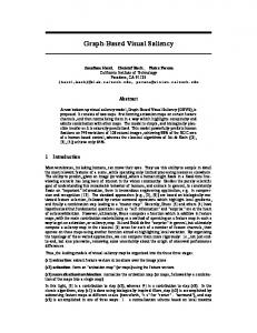
Fig. 1. Locally stand-out regions, at level 3, based on: (a) intensity, (b) orientation, and (c) colour. In (d) and (e) are shown the individual chromaticity feature maps (CR and CB).
Fig. 1 (a)-(c) shows the intensity, orientation and colour feature maps at scale 3 ( I (m, n ) , O −3 (m, n ) , C −3 ( m, n ) ) along with the individual chromaticity feature −3
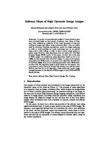
maps ( CR −3 (m, n ) , CB −3 ( m, n ) ) whose point by point addition produced the colour feature map. In Fig. 2 (a)-(c) the intensity, orientation and colour feature maps at scale 1 are shown. It is important to note that the areas that stand-out from their surround are
542
N. Tsapatsoulis and K. Rapantzikos
(a)
(b)
(c)
Fig. 2. Locally stand-out regions, at level 1, based on: (a) intensity, (b) orientation, and (c) colour
significantly smaller (proportionally) than the ones shown in Fig. 1. Therefore, a combination of the features maps at the various scales (conspicuity maps) is needed to cover both small and large stand-out objects. Combination of different scales is achieved by interpolation to the finer scale, point-by-point subtraction and application of a saturate function to the final result. The following equations describe mathematically process of combining the results of two successive scales for the orientation conspicuity map. It is obvious that the same process applies also to intensity and colour conspicuity maps:
(
)
Cˆ O− j (m, n ) = CO− ( j +1) ( m, n )) ↑ 2 m ∗hφ ( m) ↑ 2 n ∗hφ ( n ) C − j ( m, n ) = O
(−(Cˆ 1+ e
2 −J O
( m ,n ) +O − j ( m ,n )
)) − 1
(4.1)
(4.2)
where O − j (m, n ) is the orientation feature map computed at level j (see eq. 2.2), C − j (m, n ) is the orientation conspicuity map at level j, Cˆ − j (m, n ) is the interpolation O
of C
O
− ( j +1) O
(m, n ) at a finer scale j, and ↑
2m
and ↑
2n
denote up-sampling along rows
and columns respectively. An example of intensity, orientation and colour conspicuity maps computed using analysis depth equal to 3 is shown in Fig.3. After creating this intermediate multi-resolution representation (conspicuity maps per feature), where salient areas are enhanced and pop-out from the surround, an across-scale combination is applied to create a single saliency map. For this purpose a
Wavelet Based Estimation of Saliency Maps in Visual Attention Algorithms
(a)
543
(c)
Fig. 3. Conspicuity maps computed using analysis depth (Jmax) equal to 3 (a) intensity (b) orientation, and (a) colour
(a)
(c)
Fig. 4. (a) An input frame, (b) Saliency map computed at depth 1. Note that though the floodlight it is a clearly stand-out object it is not recognized as such at this level.
544
N. Tsapatsoulis and K. Rapantzikos
saturate function is applied so as to preserve the independency and added value of the particular concpicuity maps. This process is described mathematically by the following equation: S ( m, n ) =
(−(C 1+ e
2 −0 −0 −0 I ( m ,n ) +C O ( m ,n )+ CC ( m ,n )
)) − 1
(5)
where C I−0 (m, n ) , CO−0 (m, n ) , and CC−0 (m, n ) are the intensity, orientation and colour conspicuity maps respectively. Figs. 4 and 5 show examples of saliency maps computed using depths 1, 3, and 4. In the latter case objects covering as much as 20% of the whole image can be identified as standing-out from their surround.
(a)
(c)
Fig. 5. Saliency maps computed using analysis depth (Jmax) equal to (a) 3 and (b) 4. In (a) the floodlight starts appearing as a stand-out object but the overall saliency maps is rather noisy. In (b) the floodlight it is clearly a stand-out object while the saliency map is smooth.
4 Visual Trials Tests and Experimental Results To evaluate the algorithm, we simply use it as a front end; that is, once the VA-ROI areas identified the non-ROI areas in the video frames are blurred. Although this approach is not optimal in terms of expected file size gains, it has the advantage of producing compressed streams that are compatible with existing decoders [10].
Wavelet Based Estimation of Saliency Maps in Visual Attention Algorithms
545
Visual trial tests were conducted to examine the quality of the VA-ROI based encoded videos. These tests are based upon ten short video clips, namely: eye_witness, fashion, grandma, justice, lecturer, news_cast1, news_cast2, night_interview, old_man, soldier (see [11]). All video clips were chosen to have a reasonably varied content, whilst still containing humans and other objects that could be considered to be more important (visually interesting) than the background. They contain both indoor and outdoor scenes and can be considered as typical cases of news reports based on 3G video telephony. However, it is important to note that the selected video clips were chosen solely to judge the efficacy of VA ROI coding in MPEG-1 and are not actual video- telephony clips. For each video clip encoding aiming at low-bit rate (frame resolution of 144x192, frame rate 24 fps, GOP structure: IBBPBBPBBPBB) has been taken place so as to conform to the constraints imposed by 3G video telephony. Two low-resolution video-clips were created for each case, one corresponding to VA based coding and the other to standard MPEG-1 video coding. 4.1 Experimental Methodology
The purpose of the visual trial test was to directly compare VA ROI based and standard MPEG-1 encoded video where the ROI is determined using the proposed VA algorithm. A two alternative forced choice (2AFC) methodology was selected because of its simplicity, i.e., the observer views the video clips and then selects the one preferred, and so there are no issues with scaling opinion scores between different observers [12]. There were ten observers, (5 male and 5 female) all with good, or corrected, vision and all observers were non-experts in image compression (students). The viewing distance was approximately 20 cm (i.e., a normal PDA / mobile phone viewing distance) and the video clip pairs were viewed one at a time in a random order. The observer was free to view the video clips multiple times before making a decision within a time framework of 60 seconds. Each video pair was viewed twice, giving (10x10x2) 200 comparisons. Video-clips were viewed on a typical PDA display in a darkened room (i.e., daylight with drawn curtains). Prior to the start of the visual trial all observers were given a short period of training on the experiment and they were told to select the video clips they preferred assuming that it had been downloaded over a 3G mobile / wireless network. 4.2 Results
Table 1 shows the overall preferences, i.e., independent of (summed over) video clips for standard MPEG-1 and VA ROI-based encoded MPEG-1. It can be seen in that there is slight preference to standard MPEG-1 which is selected at 52.5% of the time as being of better quality. However, the difference in selections, between VA ROIbased and standard MPEG-1 encoding, is actually too small to indicate that the VA ROI-based encoding deteriorates significantly the quality of produced video. At the same time the bit rate gain, which is about 27% on average (see also Table II), shows clearly the efficiency of VA ROI based encoding.
546
N. Tsapatsoulis and K. Rapantzikos Table 1. Overall preferences (independent of video clip)
Encoding Method VA-ROI Standard MPEG -1
Preferences 95 105
Average Bit Rate (Kbps) 224.4 308.1
Table 2. Comparison of VA-ROI based and Standard MPEG-1encoding in ten video seqs
Video Clip
Eye_witness, fashion grandma justice lecturer news_cast1 news_cast2 night_interview old_man soldier Average
Encoding Method VA-ROI Standard VA-ROI Standard VA-ROI Standard VA-ROI Standard VA-ROI Standard VA-ROI Standard VA-ROI Standard VA-ROI Standard VA-ROI Standard VA-ROI Standard VA-ROI Standard
Bit Rate (Kbps) 319 386 296 354 217 256 228 318 201 274 205 297 170 270 174 335 241 321 193 270 224.4 308.1
Bit Rate Gain
17 (%) 16 (%) 15 (%) 28 (%) 27 (%) 31 (%) 37 (%) 48 (%) 25 (%) 29 (%) 27.2 (%)
Table 2 presents the bit-rates achieved for both the VA ROI based encoding and standard MPEG-1 in the individual video clips. It is clear that the bit rate gain obtained is significant, ranging from 15% to 48%. Furthermore, it can be seen from the results obtained in the night_interview video sequence, that increased bit-rate gain does not necessarily mean worse quality of the VA ROI encoded video. Bit-rate gain achieved by JPEG encoding of the individual video frames (not shown in Table 2) is on average about 21% (ranging from 14% to 28%). This indicates that the bit-rate gain is mainly due to the compression obtained for Intracoded (I) frames than for the Inter coded (P,B) ones. This conclusion strengthens the argument that smoothing of non-ROI areas may decrease the efficiency of motion compensation. Acknowledgement. The study presented in this paper was supported (in part) by the research project “OPTOPOIHSH: Development of knowledge-based Visual Attention
Wavelet Based Estimation of Saliency Maps in Visual Attention Algorithms
547
models for Perceptual Video Coding”, PLHRO 1104/01 funded by the Cyprus Research Promotion Foundation [13]
References 1. J.K. Tsotsos, S.M. Culhane, W.Y.K. Wai, Y. Lai, N. Davis, F. Nuflo, “Modeling visual attention via selective tuning”, Artificial Intelligence, vol. 78, pp. 507-545, 1995. 2. E. Dickmanns, “Expectation-based dynamic scene understanding”, in (eds.) Blake & Yuille, Active Vision, MIT Press, Cambridge Massachusetts, pp. 303-334. 3. Koch C., Ullman S., “Shifts in selective visual attention: towards the underlying neural circuitry”, Human Neurobiology, vol. 4, pp. 219-227, 1985. 4. A. M. Treisman and G. Gelade, “A feature integration theory of attention,” Cognitive Psychology, vol. 12(1), pp. 97-136, 1980. 5. Niebur, E. and Koch, C., “Computational architectures for attention” In Parasuraman, R.,editor, The Attentive Brain, chapter 9, pages 163–186. MIT Press, Cambridge, MA., 1998. 6. L. Itti, C. Koch, and E. Niebur, “A model of saliency-based visual attention for rapid scene analysis,” IEEE Transactions on Pattern Analysis and Machine Intelligence, vol. 20(11), pp. 1254-1259, 1998. 7. L. Itti, and C. Koch, “A saliency-based search mechanism for overt and covert shifts of visual attention,” Vision Research, vol. 40, pp. 1489-1506, 2000. 8. R. C. Gonzalez, R. E. Woods, Digital Image Processing, 2nd edition, Prentice Hall Inc, NJ, 2002, ISBN: 0-13-094650-8. 9. S. Mallat, “A theory for multiresolution signal decomposition: The wavelet representation”, IEEE Trans. Pattern Anal. Mach. Intell., vol. 11, pp 674-693, 1989. 10. Z. Wang, L. G. Lu, and A. C. Bovik, “Foveation scalable video coding with automatic fixation selection,” IEEE Transactions on Image Processing, vol. 12, pp. 243–254, 2003. 11. [Online] http://www.cs.ucy.ac.cy/~nicolast/research/VAclips.zip 12. M. P. Eckert and A.P. Bradley, “Perceptual models applied to still image compression,” Signal Processing, 70 (3), pp. 177–200, 1998. 13. [Online] http://www.optopiisi.com