Guido Heising, Detlev Marpe, Hans L. Cycon and Alexander P. Petukhov ...... G. BL iATTERMANN, J. RICKE, and P. MAASS, 'A Two-Layered Wavelet-Based.
TO APPEAR IN IEE PROCEEDINGS { VISION, IMAGE AND SIGNAL PROCESSING
1
Wavelet-Based Very Low Bit-Rate Video Coding Using Image Warping and Overlapped Block Motion Compensation Guido Heising, Detlev Marpe, Hans L. Cycon and Alexander P. Petukhov
Corresponding author: Detlev Marpe Heinrich-Hertz-Institute Image Processing Department Einsteinufer 37 10587 Berlin Germany
G. Heising and D. Marpe are with the Image Processing Department, Heinrich-Hertz-Institute (HHI) for Communication Technology, Berlin, Germany. H. L. Cycon is with the Fachhochschule fur Technik und Wirtschaft, Berlin, Germany. A. P. Petukhov is with the Dept. of Mathematics, University of South Carolina, Columbia, USA. October 20, 2000
DRAFT
TO APPEAR IN IEE PROCEEDINGS { VISION, IMAGE AND SIGNAL PROCESSING
2
Abstract This paper presents an algorithm for very low bit-rate video coding that combines new ideas in motion estimation, wavelet lter design, and wavelet-based coding techniques. A new motion compensation technique using image warping and overlapped block motion compensation is proposed to reduce temporal redundancies in a given image sequence. This combined motion model has the advantage of representing more complex motion than simple block matching schemes. To further improve the quality of the temporal prediction, an adaptive grid with variable density according to the varying motion activity of a given scene is generated. An adaptively switched high-quality texture interpolation is employed to cope with the problem of fractional displacements in such a way that both objective and subjective reconstruction quality is improved. Spatial decorrelation of the motion compensated residual images is performed using an one-parametric family of biorthogonal in nite impulse response (IIR) wavelet lters coupled with the highly eÆcient pre-coding scheme of `partitioning, aggregation and conditional coding' (PACC). Experimental results demonstrate signi cant improvements in objective quality of 1.0{2.3 dB PSNR in comparison to the H.263+ test model TMN10 using advanced coding options. In addition, our intra coding method provides a performance gain of 0.5 dB PSNR on the average for a test suite of various still images when comparing to the emerging still image coding standard JPEG-2000.
October 20, 2000
DRAFT
TO APPEAR IN IEE PROCEEDINGS { VISION, IMAGE AND SIGNAL PROCESSING
3
1. Introduction
Traditionally, very low bit-rate hybrid video coding schemes consist of methods of motion estimation, motion compensation and transform coding which rely on block-based techniques. One of the most successful representatives of this generation of video coding schemes is adopted by the ITU-T low bit-rate video compression standard H.263 [2]. Although this video coding standard provides a high coding eÆciency, it has the well-known drawback of su�ering from blocking artifacts especially at very low bit-rates. In this work, we propose a hybrid video coding scheme which combines very e�ective non block-based or overlapping block-based techniques for temporal prediction with an eÆcient frame-based method of spatial decorrelation. As we will demonstrate, the proposed scheme signi cantly improves coding eÆciency as well as visual quality when compared to the most eÆcient currently available video compression standard. The temporal prediction scheme of our proposed hybrid coding approach utilizes two di�erent motion models: a bilinear image warping motion model [7], [23] and an overlapped block motion compensation (OBMC) with cosine weighted window functions [21]. Although the image warping model induces a subdivision of a given image into square \blocks", the obtained motion vector eld is smooth, especially across the block boundaries. However, in the presence of objects performing di�erent movements, motion discontinuities along object boundaries are not well represented in the image warping model. In this case, OBMC may o�er an instrument for a better prediction by means of a superposition of overlapping displaced blocks from the reference frame, each weighted by a smooth cosine window. Thus, we propose an adaptive block-wise switching between both motion models controlled by the objective of minimizing a given costfunction. In addition to our previous work on this subject [9], [15], we propose to further improve the prediction by using an adaptive two-level quadtree grid instead of a xed regular grid. Our approach is similar to the idea presented in [11]. However, in contrast to this method which uses the local variance of a given frame di�erence as a criterion to decide whether a block should be split into smaller ones, we propose October 20, 2000
DRAFT
TO APPEAR IN IEE PROCEEDINGS { VISION, IMAGE AND SIGNAL PROCESSING
4
a bottom-up algorithm for generating a hierarchical grid. Our method is based on a threshold decision with respect to the variation of local prediction error energy, where the threshold depends on the given motion activity. This approach enables us to merge grid points on an initially given ne grid in stationary areas or areas with locally uniform motion, thus reducing the overall cost of side information with little impairment of prediction quality. Prediction residual frames (interframes) as well as full frames (intraframes) are decorrelated using a discrete wavelet transform (DWT) which is realized by an appropriately designed pair of in nite impulse response (IIR) lters. In contrast to biorthogonal wavelets with compact support [5] most frequently used in the image coding community, biorthogonal bases generated by recursive lters [17] o�er more exibility for the adaptation to speci c coding problems. To further enhance the transform coding scheme, an additional pre-coding part is employed where the quantized wavelet coeÆcients are pre-processed prior to arithmetic coding. This pre-coder is based on the concepts of partitioning, aggregation and conditional coding (PACC), a framework, which was rst introduced in [13] and which has proven to be very eÆcient in still image compression and very low bit-rate video coding [14], [16]. The organization of the paper is as follows. Section 2 describes the motion models, the estimation of the model parameters and the motion compensation algorithm. In Section 3, we discuss the employed type of wavelet transform together with the PACC pre-coding framework and some related pre-coding methods. Section 4 contains experimental results comparing our proposed video coding scheme to the current test model TMN10 of H.263+ and for the case of pure intra coding to the veri cation model of JPEG-2000. Conclusions can be found in Section 5. 2. Temporal Prediction Scheme
2.1 Motion Model
Two di�erent motion models are employed in order to increase the quality of the predicted frames. A bilinear geometric transform [23] is used for warping prediction October 20, 2000
DRAFT
TO APPEAR IN IEE PROCEEDINGS { VISION, IMAGE AND SIGNAL PROCESSING
(a)
Fig. 1.
5
(b)
(a) Principle of image warping prediction. (b) Spatial interpolation of motion
vectors.
and cosine weighted windows (Fig. 2 (a)) are utilized for OBMC [21]. According to Fig. 1 (a), the current frame k is subdivided into squares of 16 by 16 pels, thus obtaining a regular grid. In contrast to H.263 the positions of the motion vectors are on the vertices of the squares which leads to an additional row and column of motion vectors. The estimated vectors are used for warping predicition, OBMC or both (in case of neighboring blocks utilizing di�erent motion models). A dense motion vector eld is achieved by using a bilinear geometric transform (warp) which smoothly varies over the image. In addition to translational motion the model can describe rotation, shear and change in scale. The 8 parameters of the bilinear transform can be described by the motion vectors of 4 points. Therefore the motion vectors assigned to the four vertices of a square are used. The motion vector MV i inside a square block is interpolated from the four surrounding control point motion vectors MV : : : MV (cf: Fig. 1 (b)) using the following equation: 1
MV
i
=
dxi dyi
!
= +
October 20, 2000
4
!
!
dx dx � (~ yi x~i � y~i ) + � (x~i � y~i) dy dy ! ! dx dx � (1 x~i y~i + x~i � y~i) + dy � (x~i dy 1
2
1
2
3
4
3
4
x~i � y~i )
(1)
DRAFT
TO APPEAR IN IEE PROCEEDINGS { VISION, IMAGE AND SIGNAL PROCESSING
O B M C
6
2 D - w e ig h t fu n c tio n
w 1 1 0 ,8 0 ,6 0 ,4 0 ,2 0 1 ,0 0 ,7 y '
0 ,4 0 ,1 1
0 ,8
0 ,4
0 ,6
0
0 ,2 x '
(a)
(b)
Fig. 2. (a) 2D weighting function w1 for OBMC-based prediction. (b) Principle of n-step motion search (for n = 3).
where
x~i =
xi x
1
x y ; y~i = i x y 0
0
1
y : y 0
0
This kind of warping prediction, also known as control grid interpolation [19], leads to a motion vector eld without motion discontinuities. The smoothness across border lines is achieved by employing the same two motion vectors on both sides of the border, e:g: for x xi � �0 according to Eq. (1) only MV and MV contribute to MV i. To be more speci c, the intensity I (xi; yi ; k) of frame k at a given position (xi ; yi) is predicted by 0
p
warp
1
(xi; yi; k) = I^(xi + dxi ; yi + dyi; k 1);
3
(2)
where I^(�; �; k 1) denotes the itensity of the decoded past frame k 1. Hereby blocking artifact free predictions are obtained, which is essential for the performance of the proposed loop lter described in Section 2.4 and the wavelet transform coding part (cf: Section 3). However, in the case of sequences with di�erently moving objects, the warping model is not capable of dealing properly with motion discontinuities at the object borders. In these blocks, overlapped block motion compensation is employed by superimposing 4 predicted intensity values p ; : : : ; p using non linear weighting trans 1
October 20, 2000
trans 4
DRAFT
TO APPEAR IN IEE PROCEEDINGS { VISION, IMAGE AND SIGNAL PROCESSING
7
functions w ; : : : ; w (cf: Fig. 2 (a)): 1
p
obmc
4
(xi ; yi; k) = =
def
where x^i
and
X 4
j =1
p
pj
trans
trans 1
+p
(xi ; yi; k) � wj (xi ; yi)
� (^yi x^i � y^i) + p � (x^i � y^i) (3) � (1 x^i y^i + x^i � y^i) + p � (x^i x^i � y^i) ; trans 2
trans
trans
3
4
� � = 21 1 cos � � xxi
def
1
x x
0 0
��
; y^i
� � = 12 1 cos � � yyi
def
1
y y
0
��
0
= pj (xi ; yi; k) = I^(xi + dxj ; yi + dyj ; k 1); j = 1; : : : ; 4: Thus, the four predicted values p ; : : : ; p are computed by employing the translational motion model with one of the motion vectors MV ; : : : ; MV of the four surrounding vertices for each prediction. For each block, one bit is transmitted indicating the used prediction type. By combining these two compensation schemes, namely warping prediction and OBMC, no blocking is introduced a) between adjacent blocks using the same prediction scheme and b) around vertices of neighboring blocks using di�erent schemes. The latter is a result of using, on the one hand, the same vertex motion vectors for both schemes. On the other hand, both schemes converge to the same prediction in the vicinity of a vertex. For example, let us assume that inside the square of Fig. 1 (b) OBMC is used and outside warping prediction is employed. In that case, close to the upper left vertex warping prediction p relies only on the motion vector MV while for OBMC only the predicted value p of the respective vertex is used, which leads to equal predictions. Only little blocking artifacts may be introduced around the center of the border line of two adjacent blocks using two di�erent prediction schemes. pj
trans
trans
def
trans 1
trans 4
1
4
warp
1
trans 1
2.2 Motion Estimation
For motion estimation the current picture is subdivided into squares, thus creating a control grid. For every control point (vertex of a square), a motion vector October 20, 2000
DRAFT
TO APPEAR IN IEE PROCEEDINGS { VISION, IMAGE AND SIGNAL PROCESSING
8
is estimated by octagonal matching, i:e: nding the minimum mean-squared error (MSE) between the predicted and the current four surrounding squares of a control point (Fig. 1 (a)). In doing so the motion vectors of the eight neighboring control points are xed and only the motion vector of the center control point is changed. Because of their interdependence, the motion vectors are iteratively re ned. Therefore in each iteration the control points are scanned from top left to bottom right of the image. By using a n-step search algorithm, n = 4 iterations or, in case of larger motion, n = 6 iterations are performed with step-sizes varying in the set f16; 8; 4; 2; 1; 0:5g for a six iteration search (Fig. 2 (b)). As the number of iterations n corresponds to the number of steps, the total number of tested candidate vectors per control point amounts to 8n + 1. In order to improve the prediction in presence of large motion a hierarchical motion estimation scheme changing the grid size from coarse to ne is employed, e:g: an initial grid size of 32 � 32 followed by 16 � 16 pels can be used. The vectors of the ner grid are initialized by bilinear interpolation and subsequent rounding to half pel accurate values of the prior estimated vectors on the coarse grid. This also leads to a more homogeneous motion vector eld. To further force the estimation of smooth vector elds a Lagrangian multiplier � is used to choose the best control point motion vector considering the prediction error (in the MSE sense) and the local motion vector variance between the candidate vector MV j and the eight motion vectors MV k of its neighboring control points: estim
= arg MV min MSE(MV j ) + � � (MV k MV j ) : (4) i k The decision whether to use warping prediction or OBMC for a block is also based on Eq. (4). The prediction type yielding lower cost is chosen. To avoid a large increase of the computational workload, the MSE of the prediction error for both schemes, i:e: warping prediction and OBMC, is computed for the motion vector in question only under consideration of the bottom right subblock of the octagon (cf: Fig.1 (a)). The three other subblocks are using the prediction schemes which
MV
�
opt
October 20, 2000
j
X 8
estim
2
�
=1
DRAFT
TO APPEAR IN IEE PROCEEDINGS { VISION, IMAGE AND SIGNAL PROCESSING
9
Fig. 3. Principle of warping prediction using a variable two-level quadtree grid with square blocks of size 8 � 8 and 16 � 16 pels.
were previously assigned during motion estimation of vectors at causal positions. 2.3 Hierarchical Control Grid Interpolation
The use of a regular grid of block size 16 � 16 pels imposes a severe constraint on the motion model with respect to the most common situation where both highly active and (quasi-) stationary regions are given. For a better adaptation to this kind of scenes, we consider an extension of our motion model based on an irregular grid with square blocks of size 8 � 8 and 16 � 16 pels. To simplify the discussion, let us rst consider a pure image warping prediction. Figure 3 gives an illustration of the warping model based on such an irregular grid of squares. As usual, the prediction is obtained by relating the grid of the current frame k to a warped grid of the previous frame k 1. Note however, that the irregular grid consists of two kinds of vertices. The grid points which are connected to four other grid points are freely moving control points (CPs) as indicated in Fig. 3. The other type of grid points are bound vertices (BVs) forming a T-shaped connection between three other grid points. In contrast to a CP, the motion vector (MV) of a BV is bilinearly interpolated from the MVs of neighboring CPs, and hence need not be transmitted. The overall structure of the grid can be described by a quadtree [11]. The motion estimation process is a hierarchically organized scheme operating on successively re ned regular grids of sizes 32 � 32, 16 � 16 and 8 � 8 pels in a way, it was described in the previous section. As a result of this rst estimation step, a motion vector eld on a ne control grid G � of size 8 � 8 pels is obtained. In 8
October 20, 2000
8
DRAFT
TO APPEAR IN IEE PROCEEDINGS { VISION, IMAGE AND SIGNAL PROCESSING
10
a second step, CPs on the ne grid which are not grid points on the coarser grid G � of size 16 � 16 pels are examined in order to merge the four surrounding 8 � 8 blocks to one 16 � 16 block of those CPs which are related to homogeneously moving areas. Assuming a control point ci 2 G � n G � is given, we evaluate the local increase in prediction error �Di (in terms of MSE) obtained by replacing the actual estimated motion vector MV i of ci by its bilinearly interpolated motion vector MV i given by the four motion vectors of its neighboring control points of G � , i:e: �Di = D(MV i ) D(MV i ). If the increase in prediction error can be controlled by the norm of the di�erence jj�MV ijj of these both candidates, i:e: if �Di � � � jj�MV ijj = � � jjMV i MV i jj (5) with some given pre-determined threshold � , then MV i is substituted by MV i and the related control point ci is removed from the list of unrestricted control points, i:e: the set of potential candidate control points of the nal irregular grid. The underlying assumption of criterion (5) is that, given a homogeneous area of the motion vector eld, the prediction error D(MV i ) as a function of the optimal motion vector MV i should be a locally smooth function with bounded variation and, hence, the interpolated motion vector MV i may be a good approximation of the optimal choice MV i on the ne grid. If however, on the other hand, �Di =jj�MV ijj > � holds for the given threshold � , there is a strong evidence that either there is a local singularity in the motion vector eld or MV i represents a strong local minimum of D(�), so that in both cases, it is a reasonable choice to keep the related control point ci as a candidate of the nal irregular grid. After each control point on G � n G � has been examined according to relation (5), a third and nal merging step checks whether each of the kept control point on the ne grid G � remains an unrestricted CP with its own MV or becomes a bound vertex. This decision is based on the neighborhood of each control point ci in such a way, that, if one of the 4 immediate neighbors of ci in G � is a xed or so-called `merged' control point represented by a bilinearly interpolated MV, ci becomes a 16
16
8
8
16
16
opt
ipol
def
16
ipol
opt
16
merge
ipol
merge
opt
opt
merge
ipol
opt
opt
ipol
opt
merge
merge
opt
8
8
8
16
16
8
8
October 20, 2000
8
DRAFT
TO APPEAR IN IEE PROCEEDINGS { VISION, IMAGE AND SIGNAL PROCESSING
11
bound vertex. Note that bound vertices are not allowed to move freely but rather are collinear with two of its three neighboring grid points (cf: Fig. 3). The result of this 3-step merging process is a segmentation into 8 � 8 and 16 � 16 square blocks where the motion parameters, i:e: the motion vectors, the decisions on the predicion type (warping or OBMC) and the texture interpolation type (as described below) have to be re ned. This is done in a nal estimation process by using the same type of estimation routines as described before in Sec. 2.2. 2.4 Loop Filter
A warping predictor utilizes a higher amount of fractional motion which leads to a strong lowpass e�ect when a bilinear pixel interpolation is employed. A high quality texture interpolation reduces the lowpass e�ect of the rst order ltering of the bilinear texture interpolation. Hereby the peak signal-to-noise ratio (PSNR) can be increased up to 1.0{1.5 dB, or equivalently, bit savings up to 30% can be achieved compared to bilinear pixel interpolation [8]. Best results were obtained by using the predicted pixel at half or quarter pel position next to the unknown value for prediction. Tensor products of one-dimensional 10-tap hamming weighted sinc interpolation lters with pre-stored coeÆcients are used to compute the predictions at quarter pel positions. As this interpolation scheme emphasizes the high frequency image components the predicted image gets much sharper and less high frequency coeÆcients must be coded. Unfortunately, also unavoidable coding artifacts are more visible. Therefore, a fully non-block based coding scheme such as the proposed warping predictor and the wavelet-based residual coder should be used to avoid any blocking artifacts. In order to also reduce the ringing e�ects a block-wise adaptive interpolation scheme is employed. In this scheme, after the motion vectors are estimated it is adaptively decided for each square block whether to use the high quality or the bilinear texture interpolation. The MSE is used as a criterion for the decision, which leads to a slightly increased PSNR and an improved visual quality. This scheme can also be viewed as an adaptive loop lter. As additional side information, one bit per block October 20, 2000
DRAFT
TO APPEAR IN IEE PROCEEDINGS { VISION, IMAGE AND SIGNAL PROCESSING
12
is transmitted indicating the type of loop lter. 3. Wavelet-Based Coding
Encoding of the motion compensated P-frames as well as of initial intraframes (I-frames) is performed by means of a conventionally structured transform coding scheme. First, a wavelet transform is applied to an entire frame. Uniform scalar quantization with a central dead-zone around zero similar to that designed for H.263 is then used to map the dynamic range of wavelet coeÆcients to a reduced alphabet of decision levels. The actual statistical coding of the quantized wavelet coeÆcients is complemented by a 3-stage pre-coding process based on the PACC coding principle. In this section, we give a brief description of this coding framework along with a discussion of some issues concerning construction and choice of an appropriate family of wavelet lters. 3.1 Biorthogonal Wavelet Bases Associated with Recursive Filters
Orthogonal wavelet bases, associated with recurcive lters, were investigated in detail by Herley and Vetterly [10]. In video and image processing biorthogonal pairs of bases consisting of functions having odd or even symmetry are usually more e�ective than orthogonal non-symmetric wavelet bases. For example, in waveletbased image compression the so-called 9/7-wavelet with compact support, which was constructed in [5], is most frequently used. The wavelet bases proposed in [10], which combine orthogonality and symmetry, su�er from the fact that their adaptation to a concrete transform coding application is rather problematic due to inherently severe constraints. To overcome this problem, we propose an alternative approach. The standard approach of constructing a dual pair of biorthogonal bases consists in reducing this problem to nding solutions of the matrix equation ~ T (z M (z ) M
October 20, 2000
1
) = 2I;
(6)
DRAFT
TO APPEAR IN IEE PROCEEDINGS { VISION, IMAGE AND SIGNAL PROCESSING
where I is the identity matrix, and
0 1 h ( z ) h ( z ) C; M (z ) = B @ A
g (z ) g ( z )
13
0 1 ~ ~ h ( z ) h ( z ) C ~ (z) = B@ M A
g~(z ) g~( z )
are so-called `modulation matrices', whose components in our case are rational functions, satisfying the normalizing conditions h(1) = h~ (1) = p2. Here, and in the following, lters h and g denote low-pass and high-pass lters of the decomposition algorithm, respectively, while h~ and g~ denote the corresponding lters for reconstruction. In the polynomial case, the relations g(z ) = z h~ ( z ); g~(z ) = z h( z ) 1
1
1
1
necessarily hold. However, for rational solutions of Eq. (6) the last conditions can be violated. We consider an one-parameter family of lters 1 (7) h(z ) = p (1 + z ); 2 (2 + a)(zp + 3 + 3z + z )(z + b + z) ; h~ (z ) = (8) 4 2(2 + b)(z + a + z ) (2 + a)(z 3 +p3z z )( z + b z) ; g(z ) = (9) 4 2(2 + b) 1 1 z ; g~(z ) = p (10) 2z +a+z 1
2
1
2
1
2
2
1
1
2
where b = of lters
4
a
6
8
a
jaj > 2;
;
h(z ) =
a 6= 6.
2
In the case of a = 6 we get a more simple pair
p p1 (1 + z); h~ (z) = 2 z z + 3++6 3+z z+ z 2 1
2
2
2
:
The case jaj � 2 leads to unstable recursive lters because in this case the absolute value of roots of the denominator equals 1. We note that the choice of the lters g and g~ in Eqs. (9,10) is unusual since denominator z + a + z has moved from g to g~. From the point of view of wavelet terminology, this modi cation does not lead neither to a change of the dual pair of `multiresolution analyses' nor to a change of wavelet spaces. However, it modi es the underlying wavelet bases. 2
October 20, 2000
2
DRAFT
TO APPEAR IN IEE PROCEEDINGS { VISION, IMAGE AND SIGNAL PROCESSING
0.2
0.2
0.25
0.25 0.2
0.15 0.15
0.2
0.15
0.1
0.05
0
0.1
0 -0.05
-0.05 0.05
0.1
0.15
0.05 0.1
0.05
-0.1
-0.1
0
-0.2
-0.2 -4
-3
-2
-1
0
1
2
3
4
-0.05 -4
-3
-2
-1
0
1
2
3
4
0.2
-0.25 -4
-3
-2
-1
0
1
2
3
4
0.25 0.2
-1
0
1
2
3
4
2
3
4
-4
-3
-2
-1
0
1
2
3
4
0
-0.15
0
-0.2
-0.2 -2
1
-0.1
-0.1
-3
0
-0.05 0.05
-0.15 -4
-1
0.05 0.1
-0.05
0
-2
0.1
0.15
0
0.05
-3
0.15
0.1 0.05
0.1
-4 0.25 0.2
0.15 0.15
-0.15
0
-0.15
0.2
14
-0.05 -4
-3
-2
-1
0
1
2
3
4
-0.25 -4
-3
-2
-1
0
1
2
3
4
Fig. 4. From left to right: scaling function of analysis, analyzing wavelet, scaling function of synthesis, and synthesizing wavelet used for I-frame coding (top row) and P-frame coding (bottom row).
The nature and statistics of the images to be transformed is di�erent for intra- and interframes. In intraframe mode we have to encode ordinary still images whereas interframe mode deals with prediction residual images (P-frames). Thus the bases for both modes were optimized separately. Our numerical simulations gave optimal values a = 8 for intraframe and a = 25 for interframe mode in relations (7){(10). Graphs of the optimal basis functions are presented in Fig. 4. 3.2 Review of the PACC Pre-Coding Framework
For encoding the quantized wavelet coeÆcients, we follow the conceptual ideas presented in [13]. Next, we give a brief review of the involved techniques. For more details, the readers are referred to [13], [14]. As shown in the block diagram of Fig. 5, an initial `partitioning' stage divides each frame of quantized coeÆcients into three sub-sources: a signi cance map, indicating the position of signi cant coeÆcients, a magnitude map, holding the absolute values of signi cant coeÆcients, and a sign map with the phase information of the wavelet coeÆcients. Note, that all three sub-sources inherit the subband structure from the quantized wavelet decomposition, so that there is another partition of each subsource according to the given subband structure. In a second stage, the pre-coder performs an `aggregation' of insigni cant coeÆOctober 20, 2000
DRAFT
TO APPEAR IN IEE PROCEEDINGS { VISION, IMAGE AND SIGNAL PROCESSING
AA A AA AA AAAAAAAAA AA A A AA A AA AA AA AA AA Motion Vectors
delay
Zerotree Aggregation
Significance Map
Conditioning
Conditioning Categories
Isolated Zeros
Partitioning
Magnitude Map
Sign Map
15
Conditioning
Conditioning
A r i t h m e t i c C o d e r
Fig. 5. Schematic representation of the PACC pre-coder.
cients using the `zerotree' related data structure [12], [13] connecting insigni cant wavelet coeÆcients which share the same spatial location across di�erent scales of the octave-band decomposition. Note however, that in contrast to other zerotreebased coding methods, only zerotree roots localized in the lowest frequency bands are considered which guarantee a suÆcient coding bene t. The nal `conditioning' stage of the pre-coder supplies the elements of each source with a `context', i:e: an appropriate model for the actual coding process in the arithmetic coder. Heuristically designed prototype templates are used for conditioning of elements of the signi cance map. Typically, they consist of two parts, where the rst part is a causal neighborhood of the actual signi cance state c depending on scale and orientation of a given band. Except for the lowest frequency bands, the second part of the template utilizes additional information of the next upper level, i:e: signi cance information on the next coarser scale, which is given by the neighbors of the parent of the actual signi cance state c, thus allowing a \prediction" of the non-causal neighborhood of c. The processing of subbands is performed in the order from lowest to highest frequency bands, and the partitioned data of each band is processed such that the signi cance information is coded (and decoded) rst. This permits the construction of special conditioning states for the coding of magnitudes using the local signi cance information. Thus, the actual conditioning of magnitudes is performed by classifying signi cant coeÆcients according to the local October 20, 2000
DRAFT
TO APPEAR IN IEE PROCEEDINGS { VISION, IMAGE AND SIGNAL PROCESSING
16
variance estimated by the signi cance of their 8-neighborhood. For conditional coding of sign information a higher-order Markov model is used whose states are built of two preceding signs of a given sign event with respect to the orientation of the related band [13], [14]. Motion model parameters and all symbols generated by the pre-coder are encoded using an adaptive arithmetic coder [22]. For a fast adaptation of the models to the actual statistics, the non-binary symbols like magnitudes of coeÆcients or motion vector components are rst mapped to binary symbols with length proportional to their expected probability distribution. For intra- and interframe coding separate models are used. Consecutive P-frames as well as consecutive motion vector elds are encoded using the updated related models of the previous P-frame and motion vector eld, respectively. 4. Experimental Results
Simulations were carried out using the QCIF test sequences Container, News and Foreman (30 Hz, 300 frames, 176 � 144 pels). As a reference system we used the state-of-the-art test model TMN10 [4] of the ITU-T H.263+ [3] standardization project. The distinctive feature of TMN10 compared to its predecessors consists of an enhanced encoding strategy which rather follows a rate-distortion optimizing framework than relying on simple threshold decisions in the motion estimation stage [20]. There are several modes of operation permitted by a H.263 compliant encoder as de ned by a number of negotiable options in the annexes of H.263. For our experiments using the TMN10 coder, the unrestricted motion vector mode (Annex D), the advanced prediction mode (Annex F), the improved intra coding mode (Annex I), the deblocking lter mode (Annex J), and the modi ed quantization mode (Annex T) have been enabled. For each run on a whole sequence of both the TMN10 reference coder and our proposed coding scheme, the quantization step-size of intraand interframe coding was xed. Note, that all coding results were generated from decoded bit-streams.
October 20, 2000
DRAFT
TO APPEAR IN IEE PROCEEDINGS { VISION, IMAGE AND SIGNAL PROCESSING
17
42 40
Y-PSNR [dB]
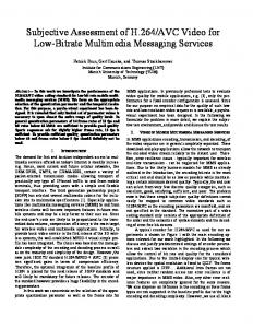
38 36 34 32 Recursive filter (a=8) Biorth. 9/7-tap filter H.263+, Annex I (TMN10)
30 28 10
15
20
25
30
35
40
45
Bitrate [kbits]
Fig. 6.
Y-PSNR [dB] over bit-rate [kbits] obtained by our proposed method with two
di�erent lter choices and the TMN10 coder using the rst frame of the QCIF
News
sequence.
4.1 Intraframe and Still Image Coding Performance
In this section, we report on the experimental performance evaluation of the intraframe coding method of our wavelet-based coding scheme. Fig. 6 shows the results for encoding the rst frame of the News sequence in intra-mode. As can be seen from the graph, a coding gain of 0.3{0.7 dB PSNR on the luminance (Y) component was achieved by our proposed coding scheme supplied with the optimal choice of recursive lters (a = 8) compared to the same scheme using the biorthogonal 9/7tap lter [5]. By using the recursive lter we also obtained visible improvements in reconstruction quality due to less ringing artifacts, especially at very low bit-rates. Compared to the advanced intra coding mode (Annex I) of H.263+, our proposed new scheme showed a consistently better performance for di�erent test sequences at various bit-rates. As shown in Fig. 6 for the rst frame of the News sequence, a PSNR gain of 0.7{3.0 dB was achieved for the luminance component where higher coding gains were obtained at higher bit-rates. Subjectively, comparing the reconstructed I-frames of our proposed coder to those of TMN10 at the same bitrate, we observed an improved quality in favor of our proposed scheme especially at low and medium rates where the reconstructions of our coder were much sharper and free of any October 20, 2000
DRAFT
TO APPEAR IN IEE PROCEEDINGS { VISION, IMAGE AND SIGNAL PROCESSING
40
18
Proposed method JPEG-2000 SPIHT
PSNR [dB]
38 36 34
Lena Goldhill
32 30 28 0.125
0.25
0.5
1
Bitrate [bpp]
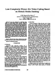
Fig. 7. PSNR [dB] over bit-rate [bpp] obtained by our proposed method and the waveletbased still image coding schemes SPIHT and JPEG-2000 using the standard grayscale test images Lena and Goldhill of size 512 � 512 pels.
blocking artifacts. Another experiment aimed at evaluating the rate-distortion (R-D) performance of our proposed method in the domain of still image coding. For this purpose, we used as reference systems the SPIHT-coder of Said and Pearlman [18] and the Veri cation Model (VM, Version 6.0) [1] of the ISO still image standardization project JPEG2000, where the latter was driven in single-layer lossy coding mode with default parameters. For a fair comparison of the di�erent wavelet-based coding methods, both reference schemes and our proposed coding scheme were operating with the same 9/7-tap lter-bank of [5]. In Fig. 7, coding results for the standard grayscale images Lena and Goldhill are presented showing that our proposed method achieved PSNR improvements of 0.2{0.5 dB over a bit-rate ranging from 0.125 to 1.0 bpp when comparing to stateof-the-art still image coders. Table 1 provides additional coding results which give evidence of the fact that the superior coding eÆciency of our intra coding method is not con ned to image material of special kind. Compared to the emerging JPEG-2000 still image standard our coding method achieved an average gain in PSNR of approx. 0.5 dB for a October 20, 2000
DRAFT
TO APPEAR IN IEE PROCEEDINGS { VISION, IMAGE AND SIGNAL PROCESSING
19
TABLE 1 Rate [bpp] vs. PSNR [dB] obtained by the proposed method and the JPEG-2000 VM for a set of JPEG-2000 test images.
Image
Rate [bpp]
Prop. method
JPEG-2000
Gain [dB]
Hotel
1.0
38.74
38.48
0.26
0.5
34.58
34.15
0.43
8 bpp
0.25
30.71
30.29
0.42
Bike
1.0
38.39
38.13
0.26
0.5
33.71
33.55
0.16
8 bpp
0.25
29.79
29.65
0.14
CT
512 � 512 pels
0.5
55.63
55.17
0.46
0.25
48.94
48.28
0.66
12 bpp
0.125
42.80
41.88
0.92
Landsat
2.0
31.54
30.66
0.88
1.0
25.95
25.43
0.52
0.5
22.65
22.23
0.42
720 � 576 pels
2048 � 2560 pels
1024 � 1024 pels 8 bpp
Average gain [dB]
:
0.46
test set with pictures of di�erent type (landscape, portrait, medical, satellite, etc.), resolution (up to 5 Megapixels) and bit depth (8{12 bpp). 4.2 Performance Evaluation of Di�erent Motion Models
In order to compare the prediction capabilities of the di�erent motion models, an experiment was performed using the Foreman sequence such that the last original frame was used for motion estimation and compensation. Four di�erent motion models have been tested, i.e. bilinear warping, aÆne warping (by subdividing each square into a top left and bottom right triangle), OBMC and BMC (block motion compensation). For the latter two in addition to the iterative n-step search algorithm an integer pel accuracy full search followed by testing the half-pel positions of the 8-neighborhood of the best candidate vector was performed (obmc fs, bmc fs). Note, that for all tests (with exception of those related to the full search method) October 20, 2000
DRAFT
TO APPEAR IN IEE PROCEEDINGS { VISION, IMAGE AND SIGNAL PROCESSING
20
3 7
P S N R [d B ]
3 6 .5 3 6 3 5 .5 3 5 3 4 .5
c bm
c_ ob m
_b m
bi lin
bi lin
_o bm
c_ fs
c
bm
bm
c_ fs
c
ob m
ob m
af fin
bi lin
c
c
e
3 4
ty p e o f p r e d ic tio n
Fig. 8. Averaged PSNR [dB] of the luminance prediction versus type of prediction using the QCIF Foreman sequence at the original frame rate of 30 Hz.
the same motion vector positions (control points, cf: Fig. 1 (a)), regular grid or block size of 16 � 16 pels and iterative motion estimation technique was employed. The only di�erence was the underlying motion model during estimation and compensation. In the graph of Fig. 8, the (average) PSNR of the luminance prediction is plotted against the prediction type. As can be seen from the graph, the bilinear warping model performs best followed by OBMC, aÆne warping and BMC. The full search strategy (fs) leads to a slightly better prediction for BMC compared to the iterative search method, whereas OBMC performs much better when combined with the iterative motion estimation scheme. So the motion estimation technique originally developed for warping prediction also performs well for OBMC. By using the proposed combination of bilinear warping and OBMC (bilin obmc) the prediction can be further improved. Combining OBMC with BMC or bilinear warping with BMC (bmc obmc, bilin bmc) leads to worse predictions. 4.3 Combined Intra- and Interframe Coding Performance
In the third and nal part of our experiments, we evaluated the performance of our full video coding scheme using the three QCIF sequence. For this purpose, the original sequences were temporally subsampled to yield a target frame rate of 10 Hz, and only the rst frame was coded in intra-mode. Figures 9 and 10 show the rate-distortion graphs as a result of these coding experiments. The R-D-curves were October 20, 2000
DRAFT
TO APPEAR IN IEE PROCEEDINGS { VISION, IMAGE AND SIGNAL PROCESSING
21
38
Y-PSNR [dB]
36
34
32
30 Bilin. warp/OBMC BMC (full search) H.263+ (TMN10)
28 0
20
40
60
80
100
120
140
160
Bitrate [kbits/sec]
Fig. 9. Averaged Y-PSNR [dB] over bit-rate [kbits/sec] using the QCIF Foreman sequence at a frame rate of 10 Hz.
plotted using averaged Y-PSNR over bit-rate, where the latter was calculated as the arithmetic mean of total bits per frame (including the rst I-frame) multiplied by the desired frame rate of 10 Hz. Note, that the H.263+ test model TMN10 was operating with Annexes D, F, I, J, and T. Compared to the TMN10 reference coder, our proposed coding scheme using the combined motion model of warping prediction and OBMC achieved a gain in average PSNR of 1.0{1.75 dB for the very active Foreman sequence (cf: Fig. 9). By using simple block motion compensation (BMC) with full search in combination with our proposed wavelet-based coding method, only marginal advantages of 0.25{0.5 dB PSNR over the TMN10 coder were obtained. Figures 10 and 11 show the results for our experiments using the Container and News sequence, respectively. Employing a xed regular control grid of size 16 � 16 pels for the combined warping/OBMC predictor a gain of 1.25{1.7 and 0.7{1.3 dB in average PSNR relative to the reference scheme was achieved for Container and News, respectively. Our proposed coding scheme supplied with the variable, two-level quadtree control grid yielded an additional PSNR gain of approx. 0.5 dB for Container and 1 dB for News. Furthermore, the visual quality of the reconstructed frames appeared to be much improved. However, at low bit-rates the reconstructed frames of our proposed October 20, 2000
DRAFT
TO APPEAR IN IEE PROCEEDINGS { VISION, IMAGE AND SIGNAL PROCESSING
22
38 37 36 Y-PSNR [dB]
35 34 33 32 Variable control grid Fixed regular grid H.263+ (TMN10)
31 30 29 20
10
30
40
50
60
70
Bitrate [kbits/sec]
Fig. 10. Averaged Y-PSNR [dB] over bit-rate [kbits/sec] using the QCIF Container sequence at a frame rate of 10 Hz. 40
Y-PSNR [dB]
38
36
34
32
Variable control grid Fixed regular grid H.263+ (TMN10)
30 10
20
30
40
50 60 70 Bitrate [kbits/sec]
80
90
100
Fig. 11. Averaged Y-PSNR [dB] over bit-rate [kbits/sec] using the QCIF
News
sequence
at a frame rate of 10 Hz.
scheme were still su�ering from some ringing noise. We are currently investigating how to reduce these artifacts by incorporating a local intra coding mode and by studying the in uence of di�erent choices of wavelet lters.
October 20, 2000
DRAFT
TO APPEAR IN IEE PROCEEDINGS { VISION, IMAGE AND SIGNAL PROCESSING
23
5. Conclusions
A new blocking artifact free video coding scheme combining warping based prediction, overlapped motion compensation and wavelet-based residual coding has been presented. The proposed algorithm uses the key techniques of an adaptive grid partition with variable density and an adaptive texture interpolation method in the temporal predictor. Switching between the image warping model and the overlapped block motion compensation allows to deal eÆciently with the problem of motion discontinuities. Intraframe and residual frame coding is performed using a speci cally tailored class of biorthogonal recursive wavelet lters along with the eÆcient coding strategy of partitioning, aggregation and context-based conditional coding. Overall, the proposed coding method has proven to yield signi cant coding gains both with respect to objective and subjective evaluation. Speeding up the motion estimation is subject to our future research. Acknowledgment
Parts of this work were supported by Deutsche Telekom Berkom GmbH, Germany, and by Russian Foundation for Basic Research under Grant No. 97-01-00443.
October 20, 2000
DRAFT
TO APPEAR IN IEE PROCEEDINGS { VISION, IMAGE AND SIGNAL PROCESSING
24
References
[1] ISO/IEC JTC 1/SC 29/WG 1, `JPEG 2000 Veri cation Model Version 6.0', Document N 1575, Jan. 2000. [2] ITU-T Recommendation H.263 `Video Coding for Low Bit-Rate Communication', Version 1, Mar. 1996. [3] ITU-T Recommendation H.263 (Version 2) `Video Coding for Low Bit-Rate Communication', Jan. 1998. [4] ITU-T Study Group 16, Question 15, `Video Codec Test Model Near Term, Version 10, TMN10 (Draft 1)', Document Q15-D-65, Apr. 1998. [5] A. COHEN, I. DAUBECHIES and J.-C. FEAUVEAU, `Biorthogonal Bases of Compactly Supported Wavelets', Comm. on Pure and Appl. Math., 1992, 45, pp. 485{560. ^ E, � B. EROL, M. GALLANT, and F. KOSSENTINI, `H.263+: Video Coding at Low [6] G. COT Bit-Rates',
IEEE Trans. on Circuits and Systems for Video Techn.
, 1998,
8
(7) pp. 849{866.
[7] G. HEISING and G. RUHL, `Video Coding Using Spatial Extrapolation Based Motion Field Segmentation',
, 1996, 2, pp. 482{485.
IEEE Int. Conf. Image Proc.
[8] G. HEISING, `Blocking Artifact Free Video Coding by Combining Warping Based Prediction with Wavelet Error Coding',
, 1997, pp. 309{314.
Proc. Picture Coding Symposium (PCS) '97
[9] G. HEISING, D. MARPE and H. L. CYCON: `A Wavelet-Based Video Coding Scheme Using Image Warping',
Proc. Int. Conf. Image Proc. (ICIP) 1998
, 1998.
[10] C. HERLEY and M. VETTERLI, `Wavelet and Recursive Filter Banks', 1993, on Signal Proc.
41
IEEE Trans.
(8) pp. 2536{2556.
[11] C.-L. HUANG and C.-Y. HSU, `A New Motion Compensation Method for Image Sequence Coding Using Hierarchical Grid Interpolation', IEEE Trans. on Circuits and Systems for Video , 1994,
Techn.
4
(1), pp. 42{51.
[12] A. LEWIS and G. KNOWLES, `Image Compression Using the 2D Wavelet Transform', ,
Trans. on Image Proc.
1
IEEE
(2), 1992, pp. 244{250.
[13] D. MARPE and H. L. CYCON, `EÆcient Pre-Coding Techniques for Wavelet-Based Image Compression', 1997,
, pp. 45{50.
Proc. PCS '97
[14] D. MARPE and H. L. CYCON, `Very Low Bit-Rate Video Coding Using Wavelet-Based Techniques',
IEEE Trans. on Circ. and Sys. for Video Techn.
, 1999,
9
(1), pp. 85{94.
[15] D. MARPE, G. HEISING, H. L. CYCON and A. P. PETUKHOV: `Video Coding Using A Bilinear Image Warping Model and Wavelet- Based Residual Coding',
Proc. SPIE
Vol. 3813,
Wavelet Application in Signal and Image Processing VI, Juli 1999, pp. 401-408. [16] D. MARPE, G. BLATTERMANN, J. RICKE, and P. MAASS, `A Two-Layered Wavelet-Based Algorithm for EÆcient Lossless and Lossy Image Compression', to appear in
IEEE Trans. on
.
Circ. and Sys. for Video Techn.
October 20, 2000
DRAFT
TO APPEAR IN IEE PROCEEDINGS { VISION, IMAGE AND SIGNAL PROCESSING
25
[17] A. P. PETUKHOV, `Biorthogonal Wavelet Bases with Rational Masks and Their Application', Preprint 1998. [18] A. SAID and W. A. PEARLMAN, `A New Fast and EÆcient Image Codec Based on Set Partitioning in Hierarchical Trees',
IEEE Trans. on Circ. and Sys. for Video Techn.
,
6
(3),
1996, pp. 243{250. [19] G. J. SULLIVAN and R. L. BAKER, `Motion Compensation for Video Compression Using Control Grid Interpolation',
Proc. Int. Conf. ASSP
, Toronto, Canada, May 1991, pp. 2713{
2716. [20] G. J. SULLIVAN and T. WIEGAND, `Rate-Distortion Optimization for Video Compression', IEEE Signal Processing Mag.
, 1998,
15,
pp. 74{90.
[21] H. WATANABE and S. SINGHAL, `Windowed Motion Compensation', ,
Visual Comm. Image Proc.
1605,
Proc. SPIE Conf.
1991, pp. 582{589.
[22] I. WITTEN, R. NEAL and J. CLEARY, `Arithmetic Coding for Data Compression', ,
ACM
30,
Comm.
1987, pp. 520{540.
[23] G. WOLBERG, `Digital Image Warping', (IEEE Computer Society Press, Los Alamitos, CA, 1990.)
October 20, 2000
DRAFT
TO APPEAR IN IEE PROCEEDINGS { VISION, IMAGE AND SIGNAL PROCESSING
26
List of Figures
1 (a) Principle of image warping prediction. (b) Spatial interpolation of motion vectors. . . . . . . . . . . . . . . . . . . . . . . . . . . . . . . . 2 (a) 2D weighting function w for OBMC-based prediction. (b) Principle of n-step motion search (for n = 3). . . . . . . . . . . . . . . . . . . . 3 Principle of warping prediction using a variable two-level quadtree grid with square blocks of size 8 � 8 and 16 � 16 pels. . . . . . . . . . . . . 4 From left to right: scaling function of analysis, analyzing wavelet, scaling function of synthesis, and synthesizing wavelet used for I-frame coding (top row) and P-frame coding (bottom row). . . . . . . . . . . . . . 5 Schematic representation of the PACC pre-coder. . . . . . . . . . . . . 6 Y-PSNR [dB] over bit-rate [kbits] obtained by our proposed method with two di�erent lter choices and the TMN10 coder using the rst frame of the QCIF News sequence. . . . . . . . . . . . . . . . . . . . . 7 PSNR [dB] over bit-rate [bpp] obtained by our proposed method and the wavelet-based still image coding schemes SPIHT and JPEG-2000 using the standard grayscale test images Lena and Goldhill of size 512 � 512 pels. . . . . . . . . . . . . . . . . . . . . . . . . . . . . . . . . . . . . . 8 Averaged PSNR [dB] of the luminance prediction versus type of prediction using the QCIF Foreman sequence at the original frame rate of 30 Hz. . . . . . . . . . . . . . . . . . . . . . . . . . . . . . . . . . . . . . . 9 Averaged Y-PSNR [dB] over bit-rate [kbits/sec] using the QCIF Foreman sequence at a frame rate of 10 Hz. . . . . . . . . . . . . . . . . . . 10 Averaged Y-PSNR [dB] over bit-rate [kbits/sec] using the QCIF Container sequence at a frame rate of 10 Hz. . . . . . . . . . . . . . . . . . 11 Averaged Y-PSNR [dB] over bit-rate [kbits/sec] using the QCIF News sequence at a frame rate of 10 Hz. . . . . . . . . . . . . . . . . . . . . . 1
October 20, 2000
5 6 9 14 15 17
18 20 21 22 22
DRAFT
TO APPEAR IN IEE PROCEEDINGS { VISION, IMAGE AND SIGNAL PROCESSING
27
List of Tables
1 Rate [bpp] vs. PSNR [dB] obtained by the proposed method and the JPEG-2000 VM for a set of JPEG-2000 test images. . . . . . . . . . . 19
October 20, 2000
DRAFT