ABCM Symposium Series in Mechatronics - Vol. 3 - pp.701-710 c 2008 by ABCM Copyright °
WEBCADBYFEATURES: COLLABORATIVE DESIGN OF FEATUREBASED PARTS THROUGH THE INTERNET Alberto J. Álvares,
[email protected] Universidade de Brasília, Departamento de Engenharia Mecânica, GIAI/GRACO, CEP 70060-900, Brasília, DF, Brazil.
João Carlos E. Ferreira,
[email protected] Universidade Federal de Santa Catarina, Departamento de Engenharia Mecânica, GRIMA/GRUCON, Caixa Postal 476, CEP 88040900, Florianópolis, SC, Brazil.
Abstract. The Internet has enabled the development of applications for the support to the design and manufacturing of industrial parts and products. Some actions have been performed by several research groups in different parts of the world aiming at conceiving product modeling system based on the technology of features to allow the sharing of information, both for the activities related to product development and for manufacturing, especially for process planning. In this work a system will be presented, which was developed for the collaborative design of feature-based cylindrical parts through the Internet, integrated with a CAD/CAPP/CAM system, using an approach based on multiagent systems. The information referring to the features is manipulated through a relational database management system. The Graphic User Interface (GUI) is implemented in Java and HTML. In this GUI, the user inputs the information on the design features that compose the part. Then these data are sent to the server. Since the part is cylindrical, the user models the part in two dimensions, and it can be visualized in 3D, through VRML. A database that stores the information on the product modeled by features, containing information associated with the form features, material features, tolerance features and technological features (superficial treatment, thermal treatment and production data) was implemented. Theses combined information allows the mapping of design features to machining features, which is fundamental for the process planning of the part. The database information is described in this article using the IDEF1X information model. Keywords: Features, CAD/CAPP/CAM, Collaborative Design, E-Manufacturing, Multi-Agents System. 1. INTRODUCTION Information Technology, especially the network communication technology and the convergence of wireless and Internet network-based technologies, is opening a new domain for building the future manufacture environments called e-Mfg (electronic-Manufacturing), using labor methods based on collaborative e-Work, especially the activities developed during product development in integrated and collaborative CAD/CAPP/CAM environments. This is a new paradigm for these computer systems based in global environments, network-centered and spatially distributed, enabling the development of activities using e-Work. This will allow the product designers to have easier communication, making it possible the sharing and collaborative design during product development, as well as the teleoperation and monitoring of the manufacturing equipment. This work presents a description of the implementation of the WebMachining system and methodology (http://WebMachining.AlvaresTech.com), developed in an e-Mfg context aiming at CAD/CAPP/CAM integration for the remote manufacture of cylindrical parts through the Internet. The methodology and its implementation are conceived with the collaborative modeling paradigm based on the synthesis of design features, in order to allow the integration of the activities of collaborative design (WebCADbyFeatures), generative process planning (WebCAPP) and manufacturing (WebTurning). The system is implemented in a distributed agent environment (agents' community), and the architecture is structured in three levels: Design, Process Planning and Manufacturing; and the Knowledge Query and Manipulation Language (KQML) was adopted as the pattern language of messages among the design, process planning and manufacturing agents. In this paper the WebCADbyFeatures system is described, which is an interface agent with the user that allows the collaborative modeling of a cylindrical part through the Internet in the context of the WebMachining system (Álvares, 2005). 2. COLLABORATIVE CAD AND RELATED SYSTEMS In design engineering practice, even more activities associated with the several manufacturing aspects are being considered during the design phase. Feature-based modeling has been used in the integration of engineering activities, from design to manufacturing. Thus, the concept of features has been used in a wide range of applications such as part design and assembly, design for manufacturing, process planning and other countless applications. These applications are migrating to heterogeneous and distributed computer environments to give support to the design and manufacturing processes, which will be distributed both in space and in time. Smith and Wright (2001) describe a distributed manufacturing service called Cybercut (http://cybercut.berkeley.edu), which makes it possible the conception of a prismatic part that will be machined using a
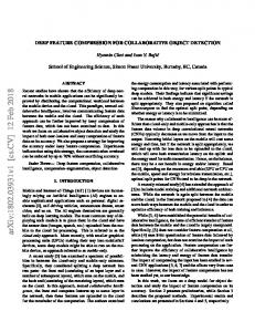
CAD/CAM system developed in Java in a context of remote manufacture. Hardwick et al. (1996) propose an infrastructure that allows the collaboration among companies in the design and manufacture of new products. This architecture integrates WWW for sharing information in the Internet using the STEP standard for product modeling. Martino et al. (1998) propose an approach to integrate the design activities with the other manufacturing activities based on features, which supports both feature-based design and feature-recognition. Collaborative modeling systems typically have a client/server architecture, differing in the functionality and data distribution between customers and servers. A common problem in the client/server systems is associated with the conflict between the limitation of the complexity of the client application and the minimization of the network load. A commitment solution can be conceived between the two ends, the so-called thin and fat clients. A pure thin client typically architecture places all the functionality in the server, which sends an image of its user interface to be shown on the client. On the other hand, a pure fat client offers total interaction and local modeling, maintaining its own local model. Communication with the server is required when it is necessary to synchronize the data modifications in the local model with the other clients. Lee et al. (1999) present the architecture of a network-centered modeling system based on features, in a distributed design environment, called NetFeature System. This approach combines feature-based modeling techniques with communication and distributed computing technologies in order to support product modeling and cooperative design activities in a computer network. Li et al. (2004) and Fuh and Li (2004) mention several distributed and integrated collaborative design systems and Concurrent Engineering, and none of such systems implements collaborative design activities integrated with process planning and remote manufacturing systems via Web for the cylindrical parts domain, with symmetrical and asymmetrical features. Most of those systems consider prismatic parts, like WebCAD 2000 of the Cybercut system, which does not implement collaborative design (Smith and Wright, 2001). The development of the WebCADbyFeatures collaborative design system differs from the above systems, because it models cylindrical parts, based on synthesis of design features (symmetrical and asymmetrical), having as motivation the development of an integrated CAD/CAPP/CAM system that allows the collaborative design through the web, in a context of Concurrent Engineering. 3. METHODOLOGY OF THE WEBMACHINING SYSTEM The integration among the production stages is one of the roads that should be explored in the search to reduce manufacturing costs and times. According to Shah and Mantyla (1995), the product modeling is the central point for achieving such integration. In an integrated production system, the product model, defined in the CAD module, should be available for other modules (CAE, CAPP, CAM, CAQ, etc) so that these can accomplish their functions. These modules should also be capable of sending feedback information to the CAD module, in order to enable the necessary changes in the part to be made during the design stage (for instance, due to problems detected in production). The use of features as an information base for product modeling is the road to reach this integration (Tönshoff et al., 1994; Salomons et al. 1993). It, especially communication network and Internet technology, is beginning a new domain for building the future CAD/CAPP/CAM environments (Lee et al., 1999), and they are potential candidates to make it possible the development of integrated systems. This will allow the designers to have easier communication, enabling the sharing and the collaborative design during the product development. With the growth of the popularity of the navigators based on WWW, it is becoming more evident that the network-centered design environment will become a new paradigm for product development. Figure 1 presents part of the IDEF0 model of the proposed system, called WebMachining (Álvares, 2005), where a methodology is presented for integrating CAD/CAPP/CAM for the remote manufacture of rotational parts through the Internet. The proposed methodology is divided into three basic activities: collaborative product modeling (WebCADbyFeatures), Generative CAPP (WebCAPP) and CAM (WebTurning). The product development procedure in the WebMachining architecture (http://WebMachining.AlvaresTech.com) begins in the collaborative modeling of a part using features, where two or more design agents cooperate during modeling the part in 2D and 3D, in a context of remote manufacturing, using the Web as a means of communication, in client-server computer model. The client, WebCADbyFeatures interface agent (fig. 2) is connected to the neutral feature modeler via Web, and it begins the instantiation of a new part to be modeled from a database, using a library of standardized form features, made available by the system. The Graphic User Interface (GUI) is implemented in Java and HTML. In this GUI, made available by browser, the user inputs the information on the design features, which will compose the part in a collaborative design context. Then, these data are sent to the server. Since the part is cylindrical, the user models the part in two dimensions, and may visualize it in 3D, through VRML. A database was implemented in MySQL that stores the information on the product modeled by features, containing information associated with the form features, material features, tolerance features and
technological features (surface treatment, thermal treatment and production data). This combined information allows the mapping of the design features into machining features, which is fundamental for process planning.
Figure 1. Modeling of the WebMachining system, using the IDEF0 methodology. After concluding and validating the model, the created part is stored and made available to the CAPP module to generate the process plan with alternatives for the part, its linearization and the representation of the linearized process plan based on STEP-NC (ISO 14649 - Part 12), as well as the generation of the NC program for a CNC lathe (http://video.graco.unb.br).
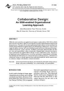
Figure 2. Main window of the WebCADbyFeatures system, showing the profile of a rotational part.
The communication with the CNC turning center Romi Galaxy/CNC Fanuc 18i-Ta is accomplished through an Ethernet connection (physical and connection layers of the ISO/OSI standard), using the TCP/IP protocol (network and transport layers of the ISO/OSI standard) associated with the application protocol Focas1/Ethernet libraries of Fanuc. Focas1 (Fanuc Open CNC API Specifications) is an API for developing applications using a standardized data structure, which has access to 300 CNC functions (http://webdnc.graco.unb.br). The teleoperation system of the CNC turning center, called WebTurning, is based on a client/server architecture. The server is composed of two modules: WebCam and WebDNC servers, represented by the programs located at a workstation (Linux platform), logically connected via TCP-IP sockets and Ethernet network to the machine-tool and to the clients, being responsible for image capture (http://video.graco.unb.br) and supervisory control of the CNC turning center, respectively; the clients' side is represented by Java Applets and HTML pages. WebTurning's teleoperation server is composed of the video server and teleoperation servers of the CNC machine, which makes it available command services, program execution, program download and upload, treatment of mistakes and other functions associated with the DNC1 communication protocol (CNC Fanuc 18i-TA), accomplishing the remote supervision of the machine. Every control action is executed locally, based on the delay of the TCP/IP protocol. The video server performs video and image capture (through four cameras) and for their distribution through the TCP/IP protocol (Internet). The other servers, associated with the teleoperation services, work in a bi-directional way, receiving commands through the Internet and sending machine status data. 4. MULTI-AGENT ARCHITECTURE FOR THE WEBMACHINING METHODOLOGY The proposed architecture for the multiagent system (MAS) can be characterized by the agents' behavior as being Deliberative, in the internal organization as being of the Blackboard type, and in the architecture itself as being of the Federated type using the Facilitator approach (Shen et al., 2001). The use of an architecture based on multi-agent system is certainly the most attractive currently, mainly due to the evolution of operating systems, especially Unix for personal computers, and the use of network communication based on TCP/IP in a client/server architecture (Shen and Norrie, 1999). In this way several types of agents working cooperatively and in a distributed way can be used in order to solve many problems associated with CAD/CAPP/CAM integration in a context of a community of agents. The JATLite (Java Agent Template Lite) software tool is used for implementing the collaborative product design system. JATLite (http://java.stanford.edu/index.html) is a software written in Java that allows the users to create agents that communicate in a robust way over the Internet. JATLite offers a basic infrastructure in which agents that are registered in an Agent Message Router (AMR), usually called facilitator or mediator, use a name and a password, being connected and disconnected through the Internet, sending and receiving messages, transferring files via FTP and usually exchanging information with other agents, through the many computers in which they run. These means are used for developing the management system of the collaborative design sessions, where a design agent interface makes it available its design for the other participant agents of the product modeling session. The proposed architecture is composed by six groups of agents: facilitator, database manager, VRML manager, collaborative design, process planning process and manufacturing. 5. FEATURE-BASED DESIGN According to Shah and Mäntylä (1995), two design-by-features methodologies are commonly used: Destruction by Machining Features and Synthesis of Design Features. The destructive approach is also known as Destructive Solid Geometry or Deforming Solid Geometry (DSG). The Destruction by Machining Features approach begins with a model of the raw material that will be machined. The part model is created by subtracting from the raw material the features that correspond to the material removed by machining operations, usually milling and drilling. The advantage of this method is that the machining features are directly available in the part model, being unnecessary feature-recognition. A disadvantage consists of the fact that the designer should have a wide knowledge of manufacturing, which forces the designer to think in terms of manufacturing features. Usually, the designer is interested, initially, in the shape of the part and in the functional aspects. In the second approach, Synthesis of Design Features, the model can be built both by union and subtraction, not being necessary to begin with a model of a raw material. In the Feature-based Design approaches, the parts are created using features directly, and the geometric model is generated from the feature-based model. This requires that the design system has generic definitions of features made available by the Library of Features, allowing the instantiation of the features for specifying dimensions, location parameters, the feature/face/edge on which it is located, and several other attributes, constraints and relationships. The WebCADbyFeatures system uses the synthesis of design features approach, using a features taxonomy based on CAM-I (1986) and in the ISO 10303-224 standard (STEP - Standard Exchange of Product Model Dates). The Destruction by Machining Features approach begins with a model of the raw material that will be machined. The part model is created by subtracting from the raw material the features that correspond to the material removed by
machining operations, usually milling and drilling. The advantage of this method is that the machining features are directly available in the part model, being unnecessary feature-recognition. A disadvantage consists of the fact that the designer should have a wide knowledge of manufacturing, which forces the designer to think in terms of manufacturing features. Usually, the designer is interested, initially, in the shape of the part and in the functional aspects. The design form features are added to the feature model, associated with the turning operations in a turning center. It also has form features that are subtracted from the part feature model, as channels and holes, associated with the operations axis C (active tool in the CNC turning center). 5.1 WebCADbyFeatures: Conceptual and Physical Modeling of Information The conceptual model of the information was conceived through the IDEF1X methodological approach (Integrated Computer Aided Manufacturing DEFinition). This model uses its own syntax and semantics, however its graphic representation is very similar to UML (Unified Modeling Language), and consequently of the Java language, which was one of the main factors for selecting this model, besides being a complete methodology, not only a graphical representation. Starting from this IDEF1X model (shown in http://WebMachining.AlvaresTech.com/db/ modelo_conceitual /idef1x/features_idef1x.pdf), the database physical model and the MySQL database management system (found in http://WebMachining.Alvarestech.com/db/modelo_fisico) were generated, and also the library of classes associated with the features. This information model is divided into domains associated with the feature database (form features, tolerance features, manufacturing features and material features) and machining technology database (machine-tool library, cutting tool library, machinability library and fixture library). The feature database is connected with the product model and the machining technology database links with the resource model. For the implementation of the data models, the server of the MySQL relational database was selected. A library of Java classes with the UML models was also developed, for a greater functionality of the database. The connection of the WebCADbyFeatures Java applet with MySQL database is done through servlets, adopting a three tiers approach. 5.2 WebCADbyFeatures: Implementation The implementation of the WebCADbyFeatures system for collaborative design of rotational parts was conceived for allowing CAD/CAPP/CAM integration, in a distributed environment through the Web. The inputs to the software are the feature model and other necessary information, and it outputs the feature model of the raw material and the finished part, which becomes an input to the CAPP module, which in turn is responsible for generating the process plan and the NC program for the corresponding part (figure 1). The computer system WebMachining (fig. 3) it is based on the architecture client/server, with use of Java, C and C++ programming languages (Object-Oriented Programming).
Figure 3. Detailed architecture: WebCADbyFeatures system modules. On the client side the GUI is represented by applets, and these are called Interface Agents. Two servers (VRML and JATLite) are implemented: 9 VRML server based on servlets (TomCat): used for generating the 3D model of the part in VRML, from the design feature model of the part;
9
JATLite Router/Facilitator server: allows the management of many sessions of collaborative product modeling, performing the coordination of communication between the many WebCADbyFeatures interface agents, as well as the other agents in the system, managing the routing of messages between the agents, system security and agent registration. It is implemented through the Agent Message Router (AMR) of the JATLite architecture. The AMR is very important in the JATLite development environment, because the agents always communicate between each other via AMR, to send an e-mail message or a file with the feature model in 2D, via SMPT and FTP, respectively.
5.2.1 Basic Characteristics of WebCADbyFeatures WebCADbyFeatures is composed by a GUI that has menus, visualization options, error messages, feature manipulation, communication with the JATLite session manager for collaborative modeling, communication with the database server, communication with VRML server, monitoring of the shop floor (WebCAM), teleoperation of the CNC turning center, among other functions. The modeling of the part begins with the access of the client to the Web page for running the CAD Java applet. The navigation in the system begins after the user's registration via PHP (Personal Home Page). Then, the applet is called, downloaded via web, and automatically the local Java machine runs the applet. It is used the GUI AWT'S standard (Abstract Windowing Toolkit) to allow a better performance and compatibility with any Java machine version 1.1, which is implemented in a native way in most browsers (Netscape, Iexplorer, among others), without need of a specific plug-in for a certain Java version, facilitating its use by the user. The first window to appear shows the initial options (figure 4a). For a non-registered user it is only possible to create a new project.
a)
c)
b) d) Figure 4. Stages in the design of a part: (a) Options window; (b) Window with data about a new project; (c) Window of data about the raw material (Solid Bar); (d) Window with modeling options. Then, a new window opens up (figure 4b) that gathers the design information. If the user does not want to alter anything, the fields are filled out with default values, based on the user's name and current date. The system guides the user, asking for the relevant information for part modeling and process planning. If the solid bar raw material is chosen, it appears a new window (figure 4c) requesting the geometric information
about a solid bar, which are its diameter and length. The last window of this preparatory phase (figure4d), provides the user the options for modeling the zero (left or right) and if he prefers to begin the modeling with the external or internal area of the part. The default is the modeling from the left-hand side, and beginning with the external features, which is the preferred design manner by the designers. Proceeding with modeling, a drawing window or main window (figure 2) opens up, where the wanted part is modeled, and it is used the available form features in the feature library. Initially, the part is modeled using the feature union method, in other words, the features are used as blocks for building the part geometry (like lego/bricks), which will be represented by a 2D profile of the part, based on the CAM-I taxonomy (CAM-I, 1986). After finishing this phase, part modeling by feature subtraction begins, i.e., volumes to be removed from the modeled part by the method of removal of material volumes, being these features associated with the C axis of the CNC turning center; i.e., rotating tool, such as keyway, eccentric holes, etc. (radial and longitudinal milling and drilling operations). The user has the option of dimensioning the drawing in 2D (zoom), move it on the screen and also generate the VRML representation at any moment, allowing thus the corresponding 3D modeling, starting from the 2D geometric and feature models, available in the information model of the part. The visualization in 3D is made through a plug-in for VRML, previously installed by the user, in her browser. When selecting the button "VRML-NOW!", the part model is sent to WebMachining server through servlets, which saves the file in the server, and it is sent to the client's browser via FTP, which calls the available VRML plug-in, allowing the navigation in the created virtual world for the part. There is the option for saving locally the geometric model in 2D and 3D (.wrl extension) and features (.ftr extension), since the security policy of the local Java machine is changed, allowing reading and writing files in the client's computer. The Java machine is configured in a safe way, preventing applets to have access to the local resources of the machine. In figure 2 an example part is shown in 2D and the 3D solid in VRML. 5.2.2 Collaborative Modeling Initially it is necessary to access the so called "WebCADbyFeatures Collaborative Design IPLayer Router Client" client interface, through the third icon of the main bar (figure 2), called "Connect WebCADbyFeatures Collaborative Design” (figure 5a). This applet is composed by several panels, which provide the necessary functionality to allow the management and the communication for developing the collaborative modeling.
Figure 5. Client interface for collaborative design: a) “WebCADbyFeatures Collaborative Design IPLayre Router Client”, show panel “Register”. b) Request of the Interface Agent “Alvares” in the Router server in the JATLite environment. The registration in the Router is made through the panel "Register" of the interface agent, filling out the fields "Agent Name = Alvares", "Password = alvares" and "Email =
[email protected]". The other data related to the Router name (Facilitator - AMR) and the TCP doors are already filled out. Then the previously registered agent is connected with the JATLite server/router, through the "Request" panel (figure 5b). The panels "Compose", "FTP" and "Reserve" are used for communication with the other agents that will participate in the collaborative modeling session.
Figure 6. Collaborative modeling between the “alvares” and “jones” agents: “alvares” agent sends the feature model to the “jones” agent.
Figure 7. Collaborative modeling between the “alvares” and “jones” agents: “alvares” agent receives the feature model from “jones” agent, after performing changes in the feature model.
On the right side of GUI (fig. 5b) information are made available on the connection with Router. KQML is used as communication language among the agents. Some directing ones used they are: sender, content, receiver, performative among dozens of another associated KQML. The figure 6 presents an example of modelling collaborative, where Interface "Alvares'" Agent shares her model of product features with the Agent of Interface "jones". Agent "Alvares" sends for FTP her project file, denominated "Álvares_2004_12_11", using Agent Router (session manager) for the Agent "jones", that will receive it directly in his GUI, and to proceed he will make the analysis and the modifications that to find convenient. To follow the Agent "jones" sends the file with their modifications, nominated for the "jones_2004_12_11" system or other name any, for Agent "Alvares", that it will receive it in her project interface, with the editions accomplished by the Agent "jones" (figure 7). The two agents can talk directly saw Router, changing messages through the panel "Compose", where an ontology is defined, in the case associated to the terminology of product development, denominated of "Project", and it is sent "Content" of this message using the language KQML, with their directing "sender: jones", "receiver: Alvares" and "performative: tell. For instance Agent "Alvares" receives message of the Agent "jones" about the modifications accomplished in the project. It can be sent email through Router, in case there is need to communicate with other agent. 6. CONCLUSION In this article the implementation of a system of development of product collaborative was described, based on modelling for synthesis of project features for pieces rotational (symmetrical and no-symmetrical features) through Internet, made available by a browser and applet Java. This software, denominated WebCADbyFeatures, it is one of the modules of the system and of the methodology WebMachining, this describes a framework for integration CAD/CAPP/CAM. It was developed a system multi-agent that makes possible the project collaborative, being implemented in an architecture client-server, constituted by servers, pages HTML and Java applets, that allow the remote user to make the modelling collaborative of the piece in 2D and her visualization in 2D and 3D, through VRML. The WebCADbyFeatures uses multi-platform servers based on servlets, JATLite, HTTP, MySQL and FTP; implemented in Java, HTML, Javascript and PHP. The servers were developed under the Linux platform, since it is more stable and robust when compared to the Windows platform, which can also be used. The client is based on a Java applet, using AWT, not being necessary a Java plug-in, making it possible total compatibility with the browsers. Also, it is not necessary any complementary software for product modeling, just the installation of a plug-in for visualization of the part in VRML. The system includes forty features in its database, and the design can be carried out in an intuitive way, and information concerning form features, references and tolerances can be quickly assigned to the part. An inexperienced user can easily use the system, since it was designed to be user-friendly, with menus containing object-oriented logic. An important characteristic of WebCADbyFeatures is that the user can model parts with splines for "general_revolution" type features, and he/she can use eccentric features (C-axis) in the design, moving beyond STEP NC-Part 12 (ISO 14649, 2003). The collaborative modeling system uses asynchronous mechanisms, in which each agent performs the modeling of the part, and shares its model with the other agents, which in turn can visualize the model, edit it, and send it back to the original agent, without a central management system for session modeling and version control. The WebMachining system can be accessed via web through the following URL: http://WebMachining.AlvaresTech.com. Many of its modules are available for use, thus providing a remote laboratory and a machining rapid prototyping system, in a context of e-Mfg (TeleManufacturing), allowing collaborative modeling, process planning and remote machining through web. Among the characteristics of the system WebCADbyFeatures is had: 9 Uses servers multi-platform based in Servlets, JATLite, HTTP, MySQL and FTP; implemented in language Java, HTML, Javascript and PHP. The servers were developed in platform Linux, for being stable and robust, when compared to the platform Windows, that can also be used; 9 is not necessary any complementary software for product modelling, just the installation of a plug-in for visualization of the piece in VRML; 9 System multi-user and multi-task, based on threads, so much on the side of the servers as on the client’s side; 9 Communication the distance among people, eliminating the geographical and temporary barriers for product development, allowing the implementation of Concurrent Engineering; 9 Modelling using splines for features of the type "general_revolution" and possibility of features introduction no concentric (axis features C), going besides STEP NC-Part 12 (ISO 14649, 2003); 9 It is integrated in a system of planning of the process generative (WebCAPP) and remote machining (WebTurning) via web (no described in this article).
7. REFERENCES Álvares, A.J. (2005). A Methodology for the CAD/CAPP/CAM Integration for the Remote Manufacture of Cylindrical Parts Based on the Internet. Ph.D. Thesis. Universidade Federal de Santa Catarina, Florianópolis, SC, Brazil (in Portuguese). Bidarra, R., Van den Berg, E., Bronsvoort, W. F., 2001, "Collaborative Modeling with Features", Proceedings of DET'01, ASME Design Engineering Technical Conferences, Pittsburgh, USA. CAM-I, Deere & Company, 1986, Part Features for Process Planning, Moline Illinois, CAM-I. Clark Corney J., Lim T., 2001, "3D Modeling with ACIS", Saxe-Coburg Publications, 2a Edition. Fuh, J.Y.H., Li. W. D., 2004, “Advances in collaborative CAD: the-state-of-the art”, Computer-Aided Design xx 1– 11. Han, J. H., Requicha, A. A. G., 1998, "Modeler-independent Feature Recognition in a Distributed Environment". Computer-Aided Design, Vol 30, No. 6, pp 453-463. Hardwick, M., Spooner, D. L., Rando, T, Morrir, K. C., 1996, "Sharing Manufavturing Information in Virtual Enterprises", Communications of the ACM, Vol 39, No. 2, pp 46-54. ISO 10303-224, 1997, Industrial Automation Systems and Integration—Product Data Representation and Exchange. Part 224: Application Protocol: Machined Product Definition for Process PlanningUsing MachiningFeatures. ISO 14649, 2003, Data model for Computerized Numerical Controlers - Part 12: Proces Data for Turning, Draft International Standad, V09. Lee, J. Y., Han, S. B., Kim, H., Park, S. B., 1999, "Network-centric Feature-based Modeling", Pacific Graphics. Li WD, Ong SK, Fuh JYH, Wong YS, Lu YQ, Nee AYC., 2004, “Featurebased design in a collaborative and distributed environment”, Computer-Aided Design,Vol 36, No. 9, pp 775–97. Martino, T. D., Falcidieno, B., Hasinger, S., 1998 "Design and Engineering Process Integration Through a Multiple View Intermediate Modeler in a Distributed Object-oriented System Environment", Computer-Aided Design, Vol 30, No. 6, pp 437-452. Salomons O.W., Houten F.J.A.M. van, Kals H.J.J., 1993, "Review of research in feature-based design, Journal of Manufacturing Systems", Vol.12, No. 2, pp 113-132. Shah, J. J., Dedhia H., Pherwani V., Solkhan S., 1997, "Dynamic Interfacing of Applications to Geometric Modeling Services Via Modeler Neutral Protocol", Computer-Aided Design, Vol 29, pp 811-824. Shah, J. J., Mäntylä, M., 1995, "Parametric and Feature-Based CAD/CAM: Concepts, Techniques, and Applications", John Wiley & Sons, New York. Shen, W., Norrie D.N., Barthés J.P.A, 2001, “Multi-Agent Systems for Concurrent Intelligent Design and Manufacturing”, Taylor & Francis, New York. Shao X., Li Y., Li P., Liu Q, 2004, “Design and implementation of a process-oriented intelligent collaborative product design system”, Computers in Industry, Vol 53, No. 2, February, pp 205-229. Shen W. , Norrie D.H., 1999, “Agent-Based Systems for Intelligent Manufacturing: A State-of-the-Art Survey” Knowledge and Information Systems, an International Journal, Vol 1, No. 2, pp 129-156. Smith, C. S., Wright, P. K., 2001, "Cybercut: An Internet-based CAD/CAM System", ASME Journal of Computing and Information Science in Engineering, Vol. 1, No. 1, pp 1-33. Sundaram, R. M., 1986, "Process Planning and Machining Sequence", Computers & Industrial Engineering, Vol. 11, pp 27-31. Tönshoff, H.K., Aurich, J.C., Baum, Th., 1994, "Configurable Feature-Based CAD/CAPP System". Proceedings of the IFIP International Conference on Feature Modeling and Recognition in Advanced CAD/CAM Systems. Valenciennes, France, pp 757-769. 8. RESPONSIBILITY NOTICE The author(s) is (are) the only responsible for the printed material included in this paper.