ABCM Symposium Series in Mechatronics - Vol. 2 - pp.345-352 Copyright © 2006 by ABCM Proceedings of COBEM 2005 Copyright © 2005 by ABCM
18th International Congress of Mechanical Engineering November 6-11, 2005, Ouro Preto, MG
MODELING OF DISTRIBUTED COLLABORATIVE CONTROL SYSTEMS OF PRODUCTION SYSTEMS Cristina Toshie Motohashi Matsusaki
[email protected]
Diolino José dos Santos Filho
[email protected] Departamento de Engenharia Mecatrônica e Sistemas Mecânicos Escola Politécnica, Universidade de São Paulo Av. Prof. Mello Moraes, 2231, CEP 05508-900 – São Paulo –S.P.
Abstract. The market needs requires the Production Systems (PS) to offer a diversity of products, at shorten product life cycles, with cost and quality exigencies. It means PS have to support concurrent execution of production processes, to coordinate the shared resources according to each resource type management and operational strategies, and to deal with time varying set of processes. The control systems of PS are challenged to meet the requirements to support such time varying, concurrent, complex processes. Not only the resource flexibility, but also the flexibility resident in the control systems is now required. This work introduces a modeling technique of distributed collaborative control systems of PS (DCCS). It proposes the multifaceted decomposition in other to approach complexity of many interrelated problems of different natures. Observing the inherent distribution of information in PS, decomposition is considered at four facets: semantic, functional, temporal and spatial decomposition. The result is a collaborative hierarchies architecture, in which a heterogeneous set of control systems collaborate to the PS global objectives. It also introduces the Extended Mark Flow Graph (E-MFG) with Communicators, which can be applied to model the individual behavior of the distributed control systems. Control systems, when seen as discrete event driven systems, can be modeled by Petri nets. E-MFG is derived from Condition/Event Petri nets; it is an interpreted net, with individual marks. Communicators are new elements of E-MFG witch supports the modeling of message based communication of control systems in the distributed environment. The communication specifications, which define the collaborative behavior of the control systems, and the modeling systematic of DCCS are briefly discussed. Keywords: distributed control systems, production systems, discrete event driven systems, Petri nets 1. Introduction The Production Systems (PS) requirements have being changing with the market necessities evolution (Gaither & Fraizer, 2001). Some decades ago, in a high volume production scenario, the PS requirements were limited to execute a sequence of process operations to produce a single type of item (Hitomi, 1990). The need to offer a variety of products increased the PS requirements to support simultaneous execution of multiple production processes. It requires coordinating the use of shared flexible resources, which is the essential problem of a global process with emerging complexity (Santos Filho, 2000). Different resource classes will present different coordination goals, which may collaborate to the PS general production objective. Moreover, the shorten products life cycle requires that PS change the set of products in an agile manner. Thus resulting in time variable set of production processes and, also time variable set of global coordination processes. The control systems of PS are challenged now to meet the requirements to support such time varying, concurrent, complex processes. Not only the resource flexibility, but also the flexibility resident in the control systems is now required. The automation technology of PS control systems has also evolved, driven by the growing processing and communication capabilities of the devices. Nowadays, the PS control strategies can be distributed to many multiple control devices that communicate across a network. In this context, there is the need of effective techniques and methodologies to design distributed control systems of PS (Park, 2002). This work introduces a modeling technique of distributed collaborative control systems of PS (DCCS) (Matsusaki, 2004). It proposes the multidimensional decomposition in other to approach complexity of many interrelated problems of different natures. This result is a collaborative hierarchies architecture, in which a heterogeneous set of control systems collaborate to the PS global objectives. It also introduces the Extended Mark Flow Graph (E-MFG) with communicators (Matsusaki, 2004), which can be applied to the behavioral model of each of the distributed control systems. Control systems, when seen as discrete event driven systems, can be modeled by Petri nets (Ho, 1989). E-MFG is derived from Condition/Event Petri nets; it is an interpreted net, with individual marks (Santos Filho, 1993). In a distributed control environment, systems interaction
occurs through exchange of messages containing information, instead of simple binary signal exchange. Communicators are new elements of E-MFG witch represent the communication interface of the modeled control system. Section 2 presents the PS concepts in a discrete event driven systems approach, considering the heterogeneous set of PS resources, classified into classes by specificity. Section 3 discusses the architecture of control systems and then, shows how to build an adequate PS control systems architecture applying the multidimensional decomposition and collaborative hierarchies organization. Section 4 introduces the E-MFG with communicators. Section 5 discusses the modeling of the communication between control systems. Section 6 shows the steps of the modeling process of DCCS of PS. Section 7 presents application examples of the introduced architecture and modeling technique. Section 8 concludes this article. 2. Production Systems and Control Systems Requirement Production Systems (PS) are systems that aim to produce items (Hitomi, 1990); (Groover, 2000). This concept can be extended to service production systems that aim to produce intangible items, meaning, to deliver services (Santos Filho, 2000); (Miyagi et al., 2000). The production processes of PS are composed of production steps. A production step is an activity or set of activities that transform the state of the item undergoing the process. Essentially, the objective of PS is the execution of these production processes. The PS can be classified as Discrete Event Driven Systems (DEDS) since the dynamical evolution is driven by the occurrence of events (Ho, 1989); (Cassandras, 1993). DEDS are composed of a set of independent elements, which functionally behave driven by events. It means that events, or actions that occur in a finite time interval, provoke a discrete state transition of the system. This class of systems can present characteristics of parallelism, synchronism, and conflict, because of the lack of a time dependent and predefined sequence of event occurrence. In the actual market scenario, in which PS must become competitive to survive, requirements of the PS control systems have increased. In order to understand the control systems requirements it is necessary to review and organize some PS aspects, as follows. • Independent elements: The resources that perform transformation activities an other activities to support production processes are distributed geographically, characterizing then the spatial distribution of elements. This spatial distribution depends on the production organization. For instance, manufacturing systems can have many different layouts (linear, cellular, job-shop.). Also, PS can be composed of production units that aggregate the resources in a particular logical organization. • Independent processes flows: depending on the PS configuration, many production processes can be run concurrently; also, depending on the flexibility, these processes can be changed to adequate to the actual state of the PS. In this sense, the global process of PS is time variable, characterizing the temporal distribution. • Heterogeneous information flow: Observing the global information flow of a PS, one perceives that the information is not homogeneous, but derived from domains that reflect the structural composition of PS, related to the classes of resources. This semantic distribution is the third aspect to be noted. • Intrinsic capabilities: Observing the requirements of techniques and tools necessary to effectively execute the production strategies, one notices the diversity of capabilities, which characterizes the functional distribution. Considering those aspects of PS and its requirements, it is possible to resume the main requirements of PS control systems: • Capability to deal with multiple semantics presented in PS; • Capability to deal with the complexity of the global process of PS. The semantic domains, each one reflecting the functional specificity of a class of elements, address to the necessity to have a specific control system for each domain. Thus the overall control system will be compound of heterogeneous control systems distributed in the semantic domains of PS. Although they are independent control systems, with its own objectives, they have to collaborate to each other in order to achieve the desired global behavior, characterizing the distributed collaborative control systems (DCCS) of PS. 3. Logical Architecture of Distributed Collaborative Control Systems 3.1 Control Systems Logical Architecture Pels et al. (1997) defines system architecture as a “set of specifications representing the components functions and their interfaces”. Thus, the definition of particular systems architecture consists on specifying the systems components, their interfaces, interrelations and restrictions. These specifications that are situated at a high level of abstraction guide the activities of subsequent steps of system development. The architecture of PS control systems can be said as a set of specifications that represent the functions of the control systems and their interfaces. Actually, control systems architecture aims to attribute the required control
Proceedings of COBEM 2005 Copyright © 2005 by ABCM
18th International Congress of Mechanical Engineering November 6-11, 2005, Ouro Preto, MG
functions to the specific components of the entire system. Consequently, each component is defined by the set of control responsibilities, which are interrelated by the coordination mechanisms of the control functions execution in the global context (Dilts, 1991). The capability of effective decision taking depends on how to distribute the responsibilities (of decision taking) to the components and how to coordinate then. The architecture determines the effectiveness of the control system. Also, when the architecture is defined, it defines the limitation or possibilities of future changes in the control systems (Dilts, 1991). These reasons show the importance of a well-elaborated architecture in PS control systems. A PS control systems architecture has to meet requirements such as reliability, extendibility and reconfigurability, and should be analyzed by the means of adequate metrics. This section presents now the evolution of control systems, with focus on the organization of the components, from centralized systems to (distributed) heterarchical systems. Then, it discusses de decomposition necessary to identify the components of the system, introducing the multifaceted decomposition of PS control systems. And finally, it presents the proposed logical architecture of PS control systems. 3.2 Multifaceted Decomposition PS such as communication systems, transport systems, and many industrial systems are one of the many application areas of multi-agent systems (MAS) (Shen & Norrie, 1999); (Parunak et al., 1998); (Jarvis et al., 2003). Weiss (2000) states that applications with the following two characteristics are candidates to MAS: a) Inherent distribution: The information and data to be processed occur in one or more form: o Occur at geographically distributed locations – spatial distribution o Occur at different moments - temporal distribution o They are structured into clusters, requiring familiarity with the corresponding language and ontology – semantic distribution o They are structured into clusters, requiring different perception, actuation and cognitive abilities – functional distribution b) Inherent complexity: the problems are relatively large to be solved by centralized software, given the software and hardware limitations, thus lack of trivial solution. It is not surprising the similarities of the characteristics of PS and MAS applications. PS control systems architectures have to be able to deal with all of those distributed aspects of information. Therefore, the architecture of distributed control systems has to be defined considering the multiple facets of decomposition: semantic decomposition, functional decomposition, temporal decomposition, spatial decomposition. A) Semantic Decomposition The semantic decomposition revels the problem domains related to the specificities of the PS elements. Any PS element has its own attributes and its functional purpose in the PS, as seen in the following examples. A vehicle is a transport resource, it has attributes that characterize it, such as dimension, load, capacity, and its purpose is to transport items between production units. An item has its product identification, description, its production process definition, and has to be transformed in the PS. These elements can be classified by functional purpose, forming the PS elements classes (transport resource class, transform resource class, production item class etc). Object oriented representation, such as UML diagrams (Booch et al., 1999), can be applied to describe the PS elements classes. Each elements class corresponds to a specific problem domain, so that, conceiving a control system for each domain results in a heterogeneous set of control systems. It is important to perceive that, although the set of PS elements classes is finite in a given case, new classes of elements can be identified in a technological evolution scenario in which appear resources with new functionality demanding resource management control. B) Functional Decomposition The functional decomposition revels the intrinsic abilities necessary to realize the control strategies applied to each of the semantic domains. To execute sequential control, to coordinate resource allocation are examples of those control abilities. Typically, the functional decomposition results in control classes like process controllers, deadlock-avoidance controllers, resource designators, etc. There may be a proper design method for each one of controller classes. As an example, the PFS/MFG methodology (Miyagi 1996) is suitable for design of production processes controllers and models the item flow through the process steps. C) Temporal Decomposition The temporal decomposition is concerned to the temporal variability of the systems´ global process, compound from the production processes and resource coordination processes. It means that the PS control systems have to support production processes insertion and the consequent modification of the resource coordination processes, by creator and destructor mechanisms based on the control meta-models. D) Spatial Decomposition
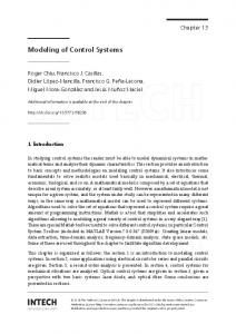
The spatial decomposition focus on the physical distribution of the PS elements, including the control execution devices. The adherence of control systems specification to this distributed situation can be achieved by applying the distributed control standards such as IEC61499 (IEC 2000) during the system development. The proposed multifaceted decomposition results in the identification of the control systems necessary to fulfill the PS requirements. It is a heterogeneous set of control systems, classified by its semantics, functionalities, time distribution, and spatial distribution. 3.3 Proposed Architecture of DCCS The proposed architecture has a set of heterogeneous control systems, result of the multifaceted decomposition. Each resource management controller forms with the process controllers a hierarchical coordination relationship. The resource management controllers communicate to each other by messages in order to act in a collaborative manner. Notice that the PS elements are classified by its specificities, so, the behavioral control of the element in a defined class has the semantic of that class. Thus, each semantic domain defines a class of control systems related to the problem domain of that elements class. For instance: The shared transformation resources in a flexible manufacturing system implies in a class of controllers concerned to problems of those elements, such as resource allocation coordination. The coordination of item flows through the production units, including deadlock avoidance strategies, is perceived as a problem of transports domain, and so, belongs to the class of transport resource control systems class. In PS with many different semantics, there will be many classes of control systems corresponding to the specificities or responsibilities, resulting in a heterogeneous system. The collaboration of those control systems gives the desired behavior of the entire PS. Figure 3.1 shows a box-connection relation diagram of the proposed architecture, where boxes represent the control systems and connections represent the communication between control systems.. The dotted lines represent the limits of semantic domains, which contain the respective class of control systems. The control systems are organized in a modified hierarchy. The lower level contains the local processes, namely the control systems of production processes. The upper level contains the global processes, namely the control systems that coordinate the shared use of resources. The communications across the upper and lower levels define the many hierarchies present in the system. The horizontal communications in the upper level generates the collaborative behavior of the control systems.
Resource Control A
Resource Control B
Resource Control N
Resource Control C
Control Process 1 Control Process 2
Control Process 3
...
Control Process n
Figure 3.1 Architecture of distributed collaborative control systems of production systems. During the design phase of control systems development, the control functions are defined. These control functions can be classified in initialization functions, operation functions, operation mode functions, maintenance functions, fault detection and recovery functions, exceptions handling functions, and others. These functions are present in almost all control systems of DCCS of PS.
Proceedings of COBEM 2005 Copyright © 2005 by ABCM
18th International Congress of Mechanical Engineering November 6-11, 2005, Ouro Preto, MG
4. E-MFG with Communicators The Mark Flow Graph (MFG) was originally proposed to model production processes control systems (Miyagi 1983). It is an interpreted graph, derived form Event/Condition Petri nets. The proposal of E-MFG (Santos Filho, 1993) introduced de individual marks, which permits the distinction of the item flows. Both MFG and E-MFG have structural elements to represent the signal transmission and the signal reception, respectively the output arcs and inhibitor or enabling arcs. The output arc, when the corresponding box condition is marked, sends a signal to the external device or other graph. The gate enables or disables the corresponding transition according to the received signal. The origin and destination of the signal are fixed to the graph elements to which the output arcs or gates are connected. The introduction of communication elements adequate the E-MFG to model the control systems and its message exchanges necessary in a distributed environment. The E-MFG with communicators maintains the individual marks and the original structural elements of E-MFG: a box, transitions, oriented arcs; and includes the transmission and reception interface elements. The boxes represent the pre and post conditions; the transitions represent the occurrence of events; oriented arcs represent the causality of events and conditions; marks represent the maintenance of a condition when in the box, and can represent distinct item flows by its attributes. Transmission interfaces emit eventual asynchronous messages when the connected box is marked; reception interfaces receive those messages and enable or disable the connected transition depending on the information received. The message transmission interface, in the object-oriented approach, corresponds to the method call of other object. It models the message emission to other systems, and is formed by send transition and send arc. The send transition represents the event of message sending; its label indicates the destination, the called method or requested service. The send arc connects the origin box to the send transmission. When the origin box is marked, the send transition fires. At the moment of message sending, the information to be transmitted has to be compound and encapsulated into the message. Figure 4.1 shows the graphic representation of transmission interface. The message reception interface models the capture and processing of the messages coming from other systems. It is formed by receive box (the receiver) and receive arc. The receive box is marked when a message arrives; the attributes of this “message mark” represent the exchanged dataset. The receive arc connects the receive box to the transition that launches the message processing. Figure 4.2 shows the graphic representation of reception interface. The system dynamic behavior is observed through the marking evolution determined by the transition firing rules and individual marks attributes maintenance rules. The interface elements have to be considered at the verifications of these rules, but notice that it does not modify the rule set of E-MFG inherited from Condition/Event Petri nets. The receive box is considered as pre condition of the connected transition. Send Transition
OBJ2.X
Send Arc
X
Receive Box
Receive Arc
Origin Box
Figure 4.1 Transmission interface of E-MFG with communicators
Figure 4.2. Reception interface of E-MFG with communicators.
5. Collaboration The collaborative behavior in the DCCS is the interaction between two or more control systems from different domains, carried out to solve one’s problem, witch is impossible to solve without the congregation of the information of other domains. The interactions occur by message exchange communications. The collaborative behavior has to be specified, considering the main two issues: specification of exchanged information and specification of interaction processes. There are adequate techniques for information modeling.. First, it determines which are the messages; then it identifies the information contained in these messages; once identified, the information can be classified and the classes of information needed to collaboration is described in UML class diagrams. This procedure of information classes’ definition follows the steps applied in ISA S95 standard (1999) in order to define the information objects between the management level and control level, according to the reference model. The information class definition procedure, adapted to the DCCS is: a) Identification of the semantic domains
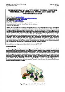
b) Identification of the control function that have to interact with other functions c) Identification of the information flow between control systems that cross over the domain frontiers. d) Classification of the information e) Description of the identified information classes in a UML class diagram. The interaction process is defined by the sequence of messages that will be sent or received, and can be represented in UML collaboration and sequence diagrams. 6. Modeling Systematic of DCCS The development of DCCS of PS is not a trivial task, as a variety of modeling techniques has to be applied o support the diversity of abilities and semantic domains, also concerning the time variation and physical distribution. The modeling systematic of DCCS, proposed in Matsusaki (2004), has three main steps: 1. Specification of logical control architecture: semantic domains identification, identification of control systems classes and the interfaces 2. Specification of control systems individual behavior: modeling of each one of the control systems classes, considering all necessary functionalities 3. Specification of collaborative behavior: identification of messages, specification of identification of information classes, specification of communication processes. The characteristics of the development process, in the context of the proposed modeling systematic, are: o Hybrid process: combines top-down and bottom-up approaches (Zhou &Dicesare, 1993) o Iterative process: there isn’t an predefined sequence of activities as in classical cascade development process, since the results of a step influences the other steps, also it implies to return to the step when it obtains the necessary information to detailed specification. o Evolutive process: each iteration generates a prototype of the specification, which evolves with the iterations until a level of detail considered sufficient to go to the next phases of development (Pressman, 2000). 7. Case Study The modeling technique was applied to a case study, which involves the control of a flexible manufacturing system, from which some parts that contribute to understand the control systems architecture and the process control modeling are presented here. The full case development can be found in (Matsusaki, 2004). Figure 7.1 illustrates de manufacturing system and its elements. It processes simultaneously many different products; the autonomous vehicles, which run on a circuit, do all the material flow; a machine and its own manipulator compose each processing station. Seven different types of products will be processed, namely: Q = { A, B, C, D, E, F, G }. Each one has a process route, with predefined sequence of stations to visit, namely, r*A, r*B, r*C, r*D, r*E, r*F, r*F. InCE
Material input stations: InAFG, InCE, InBD. Dispatch stations: OutEG, OutDF, OutABC. Processing stations: R1, R2, R3, R4, R5, R6. Autonomous vehicles: VT1, VT2. Product types: Product type A: r*A = { InAFG, R1, R2, OutABC } Product type B: r*B = { InBD, R2, R1, OutABC } Product type C: r*C = { InCE, R6, R3, R2, OutABC } Product type D: r*D = { InBD, R3, R5, OutDF } Product type E: r*E = { InCE, R5, R6, OutEG } Product type F: r*F = { InAFG, R4, R3, OutDF } Product type G: r*G = { InAFG, R1, R4, OutEG }
OutEG
OutDF R6
R5
R4
R3
R1
R2
VT1
InAE
VT2
OutAC
Figure 7.1 Flexible manufacturing system and its elements.
InBD
Proceedings of COBEM 2005 Copyright © 2005 by ABCM
18th International Congress of Mechanical Engineering November 6-11, 2005, Ouro Preto, MG
The specificity of the elements leads to the semantic domains of DCCS (dotted lined areas in the Figure 7.2); the scope of the DCCS indicates the required control functions (ellipses in the Figure 7.2): process control – executes the item process sequence; transform resources control – executes the material flow coordination, based on a deadlock avoidance policy; transport resources control – designates the vehicle to the transport requests. Concerning all the executed processes in the PS, the transform resources control and transport resources control are global processes, thus placed at the upper level of the hierarchy; both will have to collaborate in order to achieve the PS objectives.
Transport Resources Control
Transform Resources Control
Process Control C
Process Control A
Process Control D
Process Control B
Process Control G
Process Control E
Process Control F
Figure 7.2. Flexible manufacturing system DCCS architecture. The E-MFG with communicator is suitable to model the process control and also the deadlock avoidance transform resource control (material flow coordinator). The process control can be modeled applying the PFS/MFG methodology, slightly modified to fit the E-MFG with communicators. First, each processes is given a PFS model, in which the circles are passive elements while the active elements corresponds to the processing steps that allocate the transform resources (Figure 7.3). In a modular way, the activities are detailed to E-MFG models, including the communication interfaces. Figure 7.4 is the E-MFG model of the activity /Proc.A1 from the product A process. The transitions TFcontrol.req and TPcontrol .req send resource requisitions to the resource coordinators. Product A
[
In.A ]
[ Proc.A1]
[ Proc.A2]
[ Dispach A]
Figure 7.3. PFS model of product A process. VTdesignation
TFcontrolAloc
Communication with upper level systems
TPcontrol.req TFcontrol.req
/Proc.A1 Load Mach1
Mach1 processing
Mach1.comand
r2 VT loaded
unload
s2
s1 Mach1.comand
r1
s3 Mach1.comando
Go to the next station
s5
s4 VT.comand
Communication with plant level devices
Figure 7.4. E-MFG with communicators model of activity /Proc.A1
Coincidently, in this case, there is one class of control function in each semantic domain. An other case was developed where the PS was composed by many production units, that are logically related stations, requiring the coordination of material flow between production units. In that case, the transport resource domain presents the material flow coordination function and the vehicle designation function. When the scope of the DCCS is extended to include the process dispatcher, then the time facet of decomposition has to be also considered. 7. Final Remarks This work introduced a modeling technique of distributed collaborative control systems of Production Systems (DCCS). It proposes the multifaceted decomposition in other to approach complexity of many interrelated problems of different natures, which resulted in collaborative hierarchies architecture. This is a modified-hierarchical like control system architecture, where resource type specific goals are realized in a hierarchical organization leaded by the resource management coordinator, while global objectives of PS are achieved by the collaboration of the diverse resource coordinators. It is also open to the introduction of new classes of control systems deriving from new semantic domains. The Extended Mark Flow Graph (E-MFG) with communicators was introduced, for the modeling of control systems in a distributed environment. The transmission interface and reception interface support the message based information exchange. This work brought results mainly in the specification of conceptual models of distributed collaborative control systems; there are still a lot of related issues to be investigated and developed, mainly in the subsequent system development phases of design and implementation; some of them are: • Development of an integrated computer aided control systems development environment based on the proposed architecture and modeling technique. • DCCS application case studies. • To study the encapsulation of control systems, applying IEC61499 Function Block modeling elements. • To study the alternatives of low-level design procedures which guides the implementation of communicators, like the application of CORBA. References Cassandras, C.G., 1993, Discrete event systems: Modeling and performance Analysis. Irwin & Aksen. Dilts, D. M., et al., 1991, The evolution of control architecture of automated manufacturing systems; Journal of Manufacturing Systems, n.10, p.79-93. Gaither, N., Fraizer, G., 2001, Administração da Produção e Operações, Ed. Pioneira. Groover, M. P., 2000, Automation, Production Systems and Computer Integrated Manufacturing, Second edition, Prentice-Hall. Ho, Y.C., 1989, Special Issue on Dynamics of Discrete Event Systems. Proc. of IEEE, v.77, p.3-6. IEC61499-Part1, 2000, Function blocks for industrial-process measurement and control systems - Part 1: Architecture, Final Draft International Standart, International Electrotechnical Commission (IEC). ISA S95-Part 1, 1999, ANS/ISA-dS95.00.01, Enterprise-Control System Integration – Part 1: Enterprise - Control System Integration, Draft Standard 14, The Instrumentation, Systems and Automation Society (ISA), RTP North Carolina, USA, Nov. Jarvis, J., Jarvis,D. and McFarlene D., 2003, Achieving holonic control––an incremental approach, Computers in Industry, Volume 51, Issue 2, Pages 211-223, Jun. Matsusaki, C.T.M., 2004, “Modelagem de Sistemas de Controle Distribuídos Colaborativos de Sistemas Produtivos”, Doctor Thesis – Escola .Politécnica da Universidade de São Paulo, SP. Miyagi, P.E., 1988, Control System Design, Programming and Implementation for Discrete Event Production Systems by using Mark Flow Graph. Tese de Doutorado - Tokyo Institute of Technology. Japan. Miyagi, P.E., 1996, Controle Programável - Fundamentos do controle de sistemas a eventos discretos. S. Paulo, Ed. Edgard Blücher Ltda. Park, J., Reveliots, S. A., Bodner, D. A. e McGinnis, L., 2002, “A distributed event-driven control architecture for flexibly automated manufacturing systems”, International Journal Computer Integrated Manufacturing. Vol15, n2, 109-126. Parunak, H.V.D., 1998, “Practical and Industrial Applications of Agent-Based Systems”, technical report, Industrial Technology Institute. Pels, H.J., Wortmann, J.C. e Zwegers, A.J.R., 1997, “Flexibility in manufacturing: An architectural point of view”, Computers in Industry 33, 271-283. Santos Filho, D.J., 1993, “Proposta do Mark Flow Graph Estendido para a Modelagem e Controle de Sistemas Integrados de Manufatura”, master dissertation - Escola Politécnica, Universidade de São Paulo. São Paulo. Santos Filho, D.J., 2000, “Aspectos de Projeto do Controle de Sistemas Produtivos”. Tese Livre Docência - Escola Politécnica, Universidade de São Paulo. São Paulo.