IEEE TRANSACTIONS ON POWER DELIVERY, VOL. 23, NO. 3, JULY 2008
1597
Wide-Area Signal-Based Optimal Neurocontroller for a UPFC Swakshar Ray, Member, IEEE, and Ganesh K. Venayagamoorthy, Senior Member, IEEE
Abstract—The design and implementation of an optimal neurocontroller for a flexible ac transmission device—the unified power-flow controller (UPFC)—is presented in this paper. Wide area signals in a power system are used to provide auxiliary control to a UPFC in order to achieve enhanced damping of system oscillations. The neurocontroller provides auxiliary signals to the real and reactive power references of a UPFC series inverter. The design of the optimal neurocontroller is based on an adaptive critic design approach—the heuristic dynamic programming. A system identifier, referred to as the wide-area monitor), and a critic network (performance evaluator) are designed for optimizing the neurocontroller. Real-time implementation of the optimal UPFC neurocontroller for a multimachine power system is carried out successfully on a digital signal processor. The power system is simulated on a real-time digital simulator. The performance of this neurocontroller is compared with a conventional linear damping controller. Results show enhanced damping of both inter-area and intra-area modes in the power system under different operating conditions and disturbances with the neurocontroller. The improvement in the damping is also quantified using the Prony method. Index Terms—Flexible ac transmission systems (FACTS) device, heuristic dynamic programming (HDP), optimal neurocontroller, prony analysis, unified power-flow controller (UPFC), wide-area control, wide-area monitor (WAM).
I. INTRODUCTION ODAY’S deregulated market in the modern world of power system demands efficient generation, transmission and distribution due to competitive market strategies. As the power consumption is ever increasing in some regions of an electric power network, the existing transmission lines are becoming congested and overloaded in certain areas while other parts of the interconnected network remains under-utilized. The advent of flexible ac transmission systems (FACTS) devices have provided the capability to control the real and/or reactive power flow and bus voltages using modern power electronic devices. In 1991, Gyugyi proposed the most versatile of all FACTS devices—the unified power flow controller (UPFC) [1]. Since then researchers have focused on this device for solving different power system problems.
T
Manuscript received April 16, 2007; revised May 26, 2007. This work was supported by the National Science Foundation under Grants CAREER ECCS 0348221 and ECCS 0400657. Paper no. TPWRD-00209-2007. The authors are with the Real-Time Power and Intelligent Systems Laboratory, Department of Electrical and Computer Engineering, Missouri University of Science and Technology, Rolla, MO 65409-0249 USA (e-mail:
[email protected];
[email protected]). Color versions of one or more of the figures in this paper are available online at http://ieeexplore.ieee.org. Digital Object Identifier 10.1109/TPWRD.2007.916111
The main objectives of placing a UPFC in a transmission line includes 1) controlling real and reactive power flow to release congestion on certain lines and thus, realizing optimal power flow in the network and 2) provide reactive support and maintain a constant voltage at the shunt bus. In addition to the line flow control and voltage support, with proper placement, the UPFC can be utilized for damping system oscillations. If the cost of the UPFC becomes reasonable, it can be very beneficial to relieve existing stressed transmission systems. Classical techniques have been applied with simple proportional-integral controller for power flow control [2] or lead-lag compensators for damping control. But the conventional technique relies on the linearized model of the system at certain operating points. Operating point in practical power systems changes over time with the change of system configuration and change of load or generation. So, the linear model based techniques are difficult to design for getting optimal performance over multiple operating regions. Hence, different nonlinear conventional or intelligent controllers like adaptive controller, fuzzy logic, and neural network based controllers have been investigated for several years [3]–[6]. The neural network based controllers shown in [5] for a UPFC is based on adaptive control approach. The neurocontrollers respond based on only local measurements, thus, not optimized for damping inter-area modes of oscillations. Also, adaptive controllers are suboptimal controllers with adaptive parameters and it is difficult to guarantee the system stability unconditionally. Remote measurement based control has shown significant improvement in damping inter-area modes by a thyristor-controlled series capacitor (TCSC), static var compensators (SVCs), and power system stabilizers (PSSs) [7]–[11]. In today’s technology, dedicated communication channels have less than 50 ms delays for transmission of measured signals. Hence, in near future, remote measurement based wide-area control is expected to provide better stability and security to a power system. Remote signals including real and reactive powers of generators and certain lines, generator speed deviations or bus voltages can be made available to a central controller to provide robust auxiliary control signals. These control signals can enhance the performance by coordinating different control devices. Some probabilistic, adaptive and robust control methods have been investigated to generate wide-area control signals in [8]–[10]. The difficulty of modeling large nonlinear time varying networks has been the most challenging task for designing these conventional control methods. So, new emphasis has been given in the last two decades to utilize neural networks in order to identify and control the nonlinear system dynamics [12]. The recent investigations on utilizing adaptive control schemes using multilayer-perceptrons (MLPs) show improved performances for generator [13] and transmission [5]
0885-8977/$25.00 © 2008 IEEE Authorized licensed use limited to: University of Missouri. Downloaded on February 2, 2009 at 11:52 from IEEE Xplore. Restrictions apply.
1598
IEEE TRANSACTIONS ON POWER DELIVERY, VOL. 23, NO. 3, JULY 2008
controls. In recent years, adaptive critic design (ACD) based optimal neurocontrol have been proven effective for providing stabilizing control [14]–[17]. The design of an optimal damping controller for a UPFC based on wide-area signals is presented in this paper. This is an alternative approach of designing optimal damping controllers with ACD in absence of a linearized model of the system. The ACD design uses only certain measurements instead of a linearized model of the system. The external control signals are auxiliary to existing UPFC PI controls. Due to the recent advancement of communications through dedicated channels, signal transmission delay of less than 50 ms is assumed in this paper. The primary contributions of this paper are as follows. • Design of an optimal neurocontroller for a UPFC using adaptive critics and wide-area signals for power system oscillation damping. • Real-time laboratory implementation of the proposed control method. The rest of the paper is organized as follows. Section II describes the basic structure of a UPFC and its conventional PI control strategy. Section III describes the two-area multimachine power system used in this study. Section IV presents the design of the HDP optimal neurocontroller. Section V explains the real-time implementation platform. Section VI presents some implementation results for different disturbances under different operating conditions. Finally, the conclusions and future work are given in Section VII. II. UNIFIED POWER-FLOW CONTROLLER
Fig. 1. UPFC is connected between buses i and j.
Fig. 2. Control method for the series inverter of a UPFC with the neurocontroller.
A. Basic Concept UPFC is a combination of shunt and series inverters connected by a dc bus operating at a very high voltage to control the real and reactive power flow in a transmission line and the voltage at the shunt bus. The inverters are typically assumed to consist of six power electronic switches, but in practical world applications, each leg of the inverters can have several power electronic switches connected in parallel and/or in series to handle high currents and high voltages. UPFC can be modeled as a combination of series and shunt voltage or current sources [1]–[3]. In this paper, the voltage source architecture has been used. The series voltage inverter injects a voltage at the fundamental frequency with a variable magnitude and phase , in series with the transmission line. The shunt inverter injection varies according to the real and reactive power demand on the line as well as to maintain the shunt bus voltage. The capacitor bank across the dc link minimizes ripple in the dc voltage. The current flow through the transmission line, due to the controlled voltage source, results in the real and reactive power exchange between the UPFC and the system. The architecture of a UPFC and its control block diagram is shown in Fig. 1. The details of the UPFC parameters are given in Table V. B. Controls To control the 3-phase ac voltages, the voltage and currents frame. A simple PI controller is used are converted into
to generate the direct and quadrature components of the modulated voltages. The direct and quadrature components of the voltages are then used to generate the modulation index and phase shift for the PWM module. Internal controller for the seand are reference ries inverter is shown in Fig. 2. signals for the real and reactive power flows through the trans, and are the mission line. Variables proportional gains and integral time constants for series PI conand are the initial values for trollers, respectively. and direct axis voltages ( and ) at the quadrature and synchronous reference frame. The modulation index is provided to the PWM generator which genphase shift erates the gating signals for the power electronic switches in the series inverter (Fig. 2). The series inverter PI control is aided by a damping neurocontroller. For changes in operating conditions, such as load and generation changes, line outages and short duration disturbances, the neurocontroller provides robust auxiliary control signal to the PI controllers. The shunt inverter is controlled by two PI controllers similar to the series inverter control. The PI controller details can be found in [5]. The active power transfer between the shunt bus and shunt inverter is primarily controlled using the phase provided to the PWM generator. The reactive power shift support for maintaining shunt bus voltage is mainly controlled sent to the PWM generator. by the modulation index The combination can provide support to both ac bus and dc bus voltages.
Authorized licensed use limited to: University of Missouri. Downloaded on February 2, 2009 at 11:52 from IEEE Xplore. Restrictions apply.
RAY AND VENAYAGAMOORTHY: WIDE-AREA SIGNAL-BASED OPTIMAL NEUROCONTROLLER
1599
of ACDs [15]. ACDs are neural network designs for optimization over time using combined concepts of reinforcement learning and dynamic programming [14]–[17]. ACDs use two neural networks, the critic and the action network to solve the Hamilton–Jacobi–Bellman equation of optimal control. The critic network approximates the cost-to-go function of Bellman’s equation of dynamic programming, given in (1) (1)
Fig. 3. Two-area power system with a UPFC.
Fig. 4. Block diagram of the AVR-exciter model.
III. TWO-AREA MULTIMACHINE POWER SYSTEM WITH A UPFC The two-area power system [18]–[20] is a small test system that is useful in the study of inter-area oscillations like those seen in large interconnected power systems. The two-area system shown in Fig. 3 consists of two fully symmetrical areas linked together by two transmission lines. Each area is equipped with two identical synchronous generators rated 20 kV/900 MVA. All the generators are equipped with identical speed governors, turbines and exciters (Fig. 4). Initially, generators G1 and G3 are not equipped with PSSs in order to show that UPFC can damp system oscillations with an external controller. The switch S (Fig. 4) is used to add pseudo random binary signals (PRBS probing signal [21]) of small magnitudes to the excitation systems of generators for training neural networks to identify the system dynamics (explained in Section IV). The neural network that identifies the system dynamics using wide-area signals is referred to as wide-area monitor (WAM). Load is represented as constant impedances and split between the areas in such a way that Area 1 is transferring about 413 MW to Area 2. Three electromechanical modes of oscillation are present in this system; two inter-plant/intra-area modes (1.07 and 1.12 Hz), one in each area, and one inter-area low frequency mode (0.5 Hz), in which the generating units in one area oscillate against those in the other area. The two-area power system is simulated on a real-time digital simulator. The simulator platform is explained in Section V. IV. HDP OPTIMAL NEUROCONTROLLER DESIGN
where is a discount factor between 0 and 1, and is a utility function or a local performance index. The action neural network also referred to as the Actor in the ACD literature and this network provides optimal control to minimize or maximize the cost-to-go function . The actor is referred to as the neurocontroller in this paper providing an optimal damping control signal to the UPFC. Several other ACD approaches such as the dualheuristic programming (DHP) and the global dual-heuristic programming (GDHP) exist [15]. The HDP, DHP, and GDHP are all model dependent designs. The HDP based adaptive critic design illustrated in Fig. 5 is used for the neurocontroller development in this paper and is explained below. A. HDP Critic Neural Network The critic network approximates the cost-to-go function in (1). The critic network is trained forward in time, which is of great importance for real-time optimal control operation. The ability to foresee future cost and take preventive action ahead of time is important in optimal controller designs. The target for the critic during training period is derived from the Bellman’s (1) as explained in the following derivation (2):
(2) Hence, the training of the critic ensures that the optimal cost-to-go function is approximated by the HDP critic. The adaptive critic design is a neural network based optimal controller design analogous to the conventional optimal control design illustrated in [17]. In the training of the critic network, is given in (4) the objective is to minimize (3) where (3) (4) is the estimated cost-to-go by the critic netwhere work at time . The weight updates for the critic network using the standard backpropagation is given by (5):
The neurocontroller design implemented in this paper is based on the heuristic dynamic programming (HDP) approach Authorized licensed use limited to: University of Missouri. Downloaded on February 2, 2009 at 11:52 from IEEE Xplore. Restrictions apply.
(5)
1600
IEEE TRANSACTIONS ON POWER DELIVERY, VOL. 23, NO. 3, JULY 2008
Fig. 5. HDP based optimal damping control method for a UPFC.
where and are the learning rate and the weights of the critic neural network respectively. A detailed explanation for the derivation of a utility function is given in [16] and [17]. This utility function in (1) and (4) plays an important role to form the user-required optimal cost-to-go function . It is selected to give the best tradeoff between performance and the control effort. The critic neural network in Fig. 5 is a three layer feedforward network with seven input linear neurons, ten sigmoidal neurons in the hidden layer, and one output linear neuron. The critic inputs are the WAM outputs and its two delayed . values. The critic’s output is the cost-to-go function The critic neural network can be continuously trained as the system goes through changes in configuration and operating conditions. During the continued training of critic, the action or neurocontroller weight remains fixed. Intermittently, the controller can also be adjusted to adapt from the evolving critic. This procedure optimizes the controller performance over time. B. Action Neural Network/Optimal Neurocontroller The action network or neurocontroller inputs are the differences between the speeds of generators G1 (area 1) and G3 (area , differences of bus voltages of gener2), i.e., ator buses 1 and 3 and their two delayed values passed through a set of washout filters. A three-layer feedforward neural network is used to implement the damping controller. The neurocontroller consists of seven linear input neurons, 15 sigmoid hidden neurons, and two linear output neurons. The outputs of in Fig. 5) are the changes in real and the neurocontroller ( reactive power references, P and , respectively, as shown in Fig. 2. are calcuThe change in the neurocontroller weights lated by backpropagating a “1” through the trained critic netand then backpropagating the derivative work to find through the trained WAM (described below) to obas shown in Fig. 5. The error in the neurocontroller tain is the output of the WAM. More output is given by (6) where details of the training procedure can be found in [14]–[17] (6)
C. Wide-Area Monitor
The power system is nonlinear with frequent changes in operating regions due to load changes, disturbances and set point changes. The transactions on power market and commitments also require the need to change line active and reactive power flows while maintaining prescribed voltages at the sending and receiving end buses. Thus, the settings of the UPFC are required to change dynamically. The WAM provides a nonlinear model of the system with inter-area dynamics. In this paper, WAM is trained to model the inter-area dynamics of speed and voltage oscillations. The choice of measurements is based on the relationship of speed with real power and voltage with reactive power. For the HDP neurocontroller design, a neural network system identifier with one step-ahead prediction has been found sufficient in providing accurate feedback for the controller network weight updates [16], [17], and [20]. In this paper, the WAM consists of 13 linear input neurons, 15 sigmoid hidden neurons and 2 linear output neurons providing one step-ahead prediction of the speed and voltage differences between the two areas. The WAM inputs are speed differences of generators G1 (Area 1) , the voltage differences of genand G3 (Area 2), i.e., through a set of washout filters, erator buses 1 and 3 the deviation in the real power flow , the deviation in (Fig. 2) and their two delayed the reactive power flow values. The inputs to the WAM and neurocontroller are chosen to optimally damp the inter-area mode of oscillation. The oband at the jective of WAM is to predict next time step. The WAM like the controller network is trained with the standard backpropagation algorithm. For the purpose of system identification, the switch S is positioned at 1 (Fig. 4) during the training of the WAM. Typically, 5–10% of the excitation voltage is applied as a PRBS signal. The speed and voltage oscillations in between generators at two areas are then fed to the WAM to learn the wide-area system dynamics. Thus, WAM tries to identify the relation between the slow mode oscillations of the inter-areas and the real and reactive power controls of the UPFC series inverter. In practical systems, the PRBS signal can be replaced with ambient measurements during different times
Authorized licensed use limited to: University of Missouri. Downloaded on February 2, 2009 at 11:52 from IEEE Xplore. Restrictions apply.
RAY AND VENAYAGAMOORTHY: WIDE-AREA SIGNAL-BASED OPTIMAL NEUROCONTROLLER
1601
of the day. Due to continuous changes in loads, the system always has some noises and oscillations, which can be utilized for state identification [22]. D. Stability of HDP Method During the initial training period of the WAM and the critic, the controller remains offline from the system. This ensures that the random weights of the initial controller do not affect the system. During the process of training with measured data, the WAM and the critic learns the dynamics of the system. Once the weights of both WAM and critic stabilize, those weights are frozen. A trained WAM mimics the system behavior and as the system is at-least bounded input bounded output (BIBO) stable during the training phase, the WAM is also BIBO stable. The critic in the other hand learns to approximate the short or long term performance index from Bellman’s equation of dynamic programming. The performance evaluation index or is bounded because is between 0 and cost-to-go function is chosen as convex function 1 and the local utility function of the system states. Once the critic learns the function , the critic network also becomes BIBO stable. Hence, the derivatives calculated from the critic and model network is also bounded. So, the trained HDP controller with fixed weights is at-least a BIBO stable system. Once the optimization of the controller is achieved, it becomes an exponentially stable system. A few publications have also presented the mathematical proof of the stability of an ACD controller [23], [24]. V. REAL-TIME IMPLEMENTATION PLATFORM FOR THE DAMPING CONTROLLER A. Non-Real-Time Versus Real-Time Simulation Due to the complexity and expensive nature of the power system, it is very difficult to test new control methods on the practical power system. Non-real-time simulation in MATLAB, PSS/E, PSCAD, and several other power system simulation tools are ideal to evaluate a control approach. In non-real-time simulations, though the computation may take different times due to different levels of complexity, it does not create any limitation in the system performance. In practical power systems, all the controllers need to be implemented on some digital processors with certain clock speeds. Depending on the controller complexity, each sample control signal calculation may take different times. Thus, the sampling frequency has to be chosen judicially not only to avoid affecting system stability but also to accommodate all the calculations for control signal generation within a given sampling period. In addition, there can be delays in the control signal, PWM generation and firing pulse generation, which are typically ignored in the non-real studies. In real-time simulation, the feasibility of practical implementation of any algorithm or design can be tested closer to reality with hardware-in-the-loop simulation. Thus, the proposed neurocontroller is implemented on a digital signal processor and its performance is tested on the two-area power system which is simulated on a real-time power system digital simulation platform, the RTDS.
Fig. 6. Laboratory hardware setup with the RTDS.
B. Real-Time Digital Simulator and DSP The RTDS (Fig. 6) is a fully digital power system simulator capable of continuous real time operation. It performs electromagnetic transient power system simulations with a typical time step of 50 ms utilizing a combination of custom software and hardware. The proprietary operating system used by the RTDS guarantees “hard real time” during all simulations [25]. It is an ideal tool for the design, development and testing of power system protection and control schemes. With a large capacity for both digital and analogue signal exchange through numerous dedicated high speed I/O ports, physical protection and control devices are connected to the simulator to interact with the simulated power system. The real time simulator software is divided into two main categories, namely the graphical user interface and the underlying solution algorithms for network equations and component models. All aspects of simulator operation, from constructing simulation circuits to recording simulation results, are controlled through the user friendly graphical interface RSCAD. The WACS consisting of the WAM, critic and neurocontroller is implemented on the Innovative Integration M67 DSP card (based on the TMS3206701 processor), operating at 160 MHz, hosted on a Pentium III 433 MHz personal computer. The M67 DSP card is equipped with two A4D4 modules [26]. Each A4D4 module is having four analog-to-digital (A/D) converters and four digital-to-analog (D/A) converters. The interface between DSP and RTDS (power system) in laboratory setup is shown in Fig. 6. For the controller development, a sampling frequency of 40 Hz (period of 25 ms) is used in the DSP. VI. RESULTS AND DISCUSSIONS The main objective in this paper is to show the effectiveness of a neurocontroller for damping inter-area modes. Hence, speed and voltage measurements have been used for the test case. Practically, any measurements such as phasor measurements of voltage and current or real power flow through lines can easily be used with no major modification to the proposed design if the measurements exhibit inter-area modes of oscillation. A. HDP Controller Results The critic network, neurocontroller and WAM are trained sequentially as described in Section IV. Once the neural network weights do not change after sometime of continual training,
Authorized licensed use limited to: University of Missouri. Downloaded on February 2, 2009 at 11:52 from IEEE Xplore. Restrictions apply.
1602
IEEE TRANSACTIONS ON POWER DELIVERY, VOL. 23, NO. 3, JULY 2008
TABLE I DIFFERENT OPERATING CONDITIONS
Fig. 7. Block diagram of the linear lead-lag compensator based damping controller.
Fig. 9. Speed deviation of generator G1 and G3 for 2nd operating condition for a 167 ms short circuit fault at bus 7.
Fig. 8. Speed deviation of generator G1 and G3 for a 167 ms short circuit fault at bus 7 under 1st operating condition.
Fig. 10. Speed deviation of generator G1 and G3 for 3rd operating condition for a 167 ms short circuit fault at bus 7.
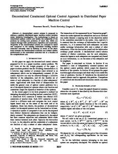
the critic is said to have approximated the Hamilton–Jacobian–Bellman equation of dynamic programming with a finite boundary in time. The discount factor is chosen as 0.8 for acceptable performance in this application. The neurocontroller output signal can then be applied to the UPFC series branch real and reactive power references to provide optimal damping to inter-area oscillations. Three different operating conditions as given in Table I are simulated to validate the robustness of the proposed controller. Different disturbance tests are carried out at all these operating conditions with different control methods, namely only UPFC internal controller (No damping control), linear lead-lag compensator based damping controller (Fig. 7) and the HDP optimal damping controller. The parameters of the linear controller are optimized for a single operating point using time domain simulation. Figs. 8–10 and show the speed responses of generators G1 and G3 with different controllers for a 167 ms short circuit fault applied at bus 7 (Fig. 3). For all the three operating conditions, HDP controller exhibits better damping performance. The linear damping controller performance in terms of the settling time degrades as the inter-area power transfer increases from 246 MW to 490 MW. The HDP controller provides
consistent damping through out the different levels of power transfers. All these tests are carried out without any PSS connected to the generators as to show the effectiveness of UPFC for providing damping to the system oscillatory modes. Further analysis on the quantification of damping with the optimal HDP controller is provided in Section VI-C. To verify the implications of HDP damping controller in presence of PSSs in the system, two PSSs are then connected to generators G1 (Area 1) and G3 (Area 3). Fig. 11 shows that even with PSSs in the system UPFC aided by HDP damping controller provides better damping and reduces the settling time of the system oscillatory modes. As a 2nd disturbance scenario, a temporary line outage simulating an open circuit in one line that changes the Thevenin’s impedances seen by the generators have been presented in Figs. 12 and 13. In this test, a 200 ms transmission line outage is simulated in one of the parallel lines between buses 8 and 9 in Fig. 4. Responses of the generators G1 and G3 have been presented for 1st and 3rd operating conditions in Figs. 12 and 13, respectively. Though the speed oscillations due to the line outage is small compared to the short circuit disturbance, the response shows enhanced damping with the HDP neurocontroller signal
Authorized licensed use limited to: University of Missouri. Downloaded on February 2, 2009 at 11:52 from IEEE Xplore. Restrictions apply.
RAY AND VENAYAGAMOORTHY: WIDE-AREA SIGNAL-BASED OPTIMAL NEUROCONTROLLER
1603
TABLE II FREQUENCY AND DAMPING OF THE GENERATORS UNDER 1ST OPERATING CONDITION
TABLE III FREQUENCY AND DAMPING OF THE GENERATORS UNDER 2ND OPERATING CONDITION
Fig. 11. Speed deviation of generator G1 and G3 for 3rd operating condition for a 167 ms short circuit fault at bus 7 with PSS and damping controller.
disturbances for mitigating inter-area mode of oscillations under different operating conditions. In Figs. 8 and 11–13, it can be observed that the steady-state speed deviations are nonzero. Due to governor droop setting of 5%, the steady-state operating speed of each generator under different conditions are different but within acceptable limits. The speed deviations shown in the figures are the differences of generators’ speeds and the nominal value of 377.14 rad/s. B. Stability Analysis
Fig. 12. Speed deviation of generator G1 and G3 for a 200 ms outage of one of the parallel transmission lines between buses 8 and 9 in Fig. 4 under 1st operating condition.
Fig. 13. Speed deviation of generators G1 and G3 for a 200 ms outage of one of the parallel transmission lines between buses 8 and 9 in Fig. 4 under 3rd operating condition.
applied to the UPFC series inverter. This proves that the proposed controller is effective and robust for both small and large
The stability of the closed loop two-area power system with the wide-area damping controller designed in this paper has been investigated using the Prony analysis method. This analytical tool provides the modes of the system from the impulse response. During a short circuit, the system faces impulsive force and the post-fault time domain response is used to find the modes of the system and thereby, the oscillation frequencies and damping associated with each mode. Prony analysis [27], [28] is an extension of Fourier analysis and it helps to find the modal contents by estimating frequency, damping and phase of a signal. This analysis tool is useful to provide information on the stability of the system at the operating point of concern without any need of extensive technique for linearization of the complete system model. The analysis is performed on the measured data; hence no prior information regarding the system is required. The prony analysis is applied on the short circuit response of the speed of generators G1 and G3 to find the slow mode frequencies and damping of the closed loop system. The frequencies and damping found from both the speed signals are quite similar. Tables II–IV show frequencies and their corresponding damping ratios with different controllers for 1st, 2nd, and 3rd operating conditions. It can be observed that the effect of the HDP neurocontroller is predominant for the inter-area modes (between 0.2 Hz to 0.8 Hz) as the controller has been specifically trained to damp out inter-area oscillations, but in addition some improvement is also observable for the intra-area modes. The frequency and damping found from the prony analysis method
Authorized licensed use limited to: University of Missouri. Downloaded on February 2, 2009 at 11:52 from IEEE Xplore. Restrictions apply.
1604
IEEE TRANSACTIONS ON POWER DELIVERY, VOL. 23, NO. 3, JULY 2008
TABLE IV FREQUENCY AND DAMPING OF THE GENERATORS UNDER 3RD OPERATING CONDITION
low cost microcontroller can be used to implement the trained neurocontroller. The real-time implementation demonstrates the potential for future practical real world deployment. The proposed external wide-area measurements-based damping controller design can be extended to other FACTS devices like SVCs, TCSCs, and STATCOMs in the future. REFERENCES
TABLE V UPFC PARAMETERS
shows the existence of same inter-area modes (0.48–0.5 Hz) for all the three operating conditions, but the intra-area modes are different. With different controller in the closed loop, the modes of the system shifts. Typically, the inter-area mode remains in the range of 0.2 Hz to 0.8 Hz and intra-area or local modes remain in the range of 0.8 Hz to 2.0 Hz. The damping improvement observed with linear damping controller is between 10% to 12% for inter-area mode and 2% to 5% for intra-area modes. The proposed HDP neurocontroller provides 17% to 27% improvement in damping for inter-area mode and 2% to 17% for intra-area or local modes. VII. CONCLUSION This paper has presented the design of a neural network based optimal damping controller using wide-area signals to provide auxiliary control to a UPFC series inverter. Adaptive critics allow the design of a neurocontroller with fixed weights to provide optimal performance. The beauty of this design is that its stability can be verified using linear analysis similar to any other linear or nonlinear controller. The wide-area signals taken from remote generators provide estimation of the interaction between the different areas and thus the optimal neurocontroller enhances damping of the inter-area oscillations existing in the multi-area systems. The real-time implementation of the neurocontroller was carried out on a DSP using measured speed and voltage signals from the two-area multimachine power system implemented on the RTDS. The training of the critic, WAM and the controller requires a lot of computation during the development. Once the weights of the critic and neurocontroller stabilize, the controller weights are fixed and only the feedforward computation needs to be carried out online during regular operation. Therefore, a
[1] L. Gyugyi, C. D. Schauder, S. L. Williams, T. R. Rietman, D. R. Torgerson, and A. Edris, “The unified power flow controller: A new approach to power transmission control,” IEEE Trans. Power Del., vol. 10, no. 2, pp. 1085–1097, Apr. 1995. [2] S. Kannan, S. Jayaram, and M. M. A. Salama, “Real and reactive power coordination for a unified power flow controller,” IEEE Trans. Power Syst., vol. 19, no. 3, pp. 1454–1461, Aug. 2004. [3] B. Lu and B. T. Ooi, “Unified power flow controller (UPFC) under nonlinear control,” in Proc. Power Conversion Conf., Osaka, Japan, Apr. 2002, vol. 3, pp. 1118–1123. [4] J.-C. Seo, S.-I. Moon, J.-K. Park, and J.-W. Choe, “Design of a robust UPFC controller for enhancing the small signal stability in the multimachine power systems,” in Proc. Winter Meeting IEEE Power Eng. Soc., Columbus, OH, 2001, vol. 3, pp. 1197–1202. [5] G. K. Venayagamoorthy and R. P. Kalyani, “Two separate continually online-trained neurocontrollers for a unified power flow controller,” IEEE Trans. Ind. Appl., vol. 41, no. 4, pp. 906–916, Jul./Aug. 2005. [6] P. K. Dash, S. Mishra, and G. Panda, “A radial basis function neural network controller for UPFC,” IEEE Trans. Power Syst., vol. 15, no. 4, pp. 1293–1299, Nov. 2000. [7] M. Zima and G. Andersson, “Wide area monitoring and control as a tool for mitigation of cascading failures,” in Proc. Int. Conf. Probabilistic Methods Appl. Power Syst., Ames, IA, Sep. 12–16, 2004, pp. 663–669. [8] R. Majumder, B. Choudhuri, and B. C. Pal, “A probabilistic approach to model-based adaptive control for damping of interarea oscillations,” IEEE Trans. Power Syst., vol. 20, no. 1, pp. 367–374, Feb. 2005. [9] B. Choudhuri, R. Majumder, and B. C. Pal, “Application of multiplemodel adaptive control strategy for robust damping of interarea oscillations in power system,” IEEE Trans. Control Syst. Technol., vol. 12, no. 5, pp. 727–736, Sep. 2004. [10] R. Majumder, B. C. Pal, C. Dufour, and P. Korba, “Design and realtime implementation of robust FACTS controller for damping interarea oscillation,” IEEE Trans. Power Syst., vol. 21, no. 2, pp. 809–816, May 2006. [11] F. Okou, L. A. Dessaint, and O. Akhrif, “Power systems stability enhancement using a wide-area signals based hierarchical controller,” IEEE Trans. Power Syst., vol. 20, no. 3, pp. 1465–1477, Aug. 2005. [12] K. S. Narendra and K. Parthasarathy, “Identification and control of dynamical systems using neural networks,” IEEE Trans. Neural Netw., vol. 1, no. 1, pp. 4–27, Mar. 1990. [13] G. K. Venayagamoorthy and R. G. Harley, “Two separate continually online-trained neurocontrollers for excitation and turbine control of a turbogenerator,” IEEE Trans. Ind. Appl., vol. 38, no. 3, pp. 887–893, May. 2002. [14] P. J. Werbos, D. A. White and D. A. Sofge, Eds., “Approximate dynamic programming for real time control and neural modeling,” Handbook Intelligent Control, pp. 493–525, 1992. [15] D. V. Prokhorov and D. C. Wunsch, “Adaptive critic designs,” IEEE Trans. Neural Netw., vol. 8, no. 5, pp. 997–1007, Sep. 1997. [16] G. K. Venayagamoorthy, R. G. Harley, and D. C. Wunsch, “Comparison of heuristic dynamic programming and dual heuristic programming adaptive critics for neurocontrol of a turbogenerator,” IEEE Trans. Neural Netw., vol. 13, no. 3, pp. 764–773, May. 2002. [17] P. Jung-Wook, R. G. Harley, and G. K. Venayagamoorthy, “Adaptive-critic-based optimal neurocontrol for synchronous generators in a power system using MLP/RBF neural networks,” IEEE Trans. Ind. Appl., vol. 39, no. 5, pp. 1529–1540, Sep. 2003. [18] M. Klein, G. J. Rogers, and P. Kundur, “A fundamental study of interarea oscillations in power systems,” IEEE Trans. Power Syst., vol. 6, no. 3, pp. 914–921, Aug. 1991. [19] P. Kundur, Power System Stability and Control. New York: McGrawHill, 1994. [20] G. K. Venayagamoorthy and S. Ray, “Real-time implementation of a neural network based optimal wide area control scheme for a power system,” presented at the IEEE Ind. Applicat. Annu. Meeting, Hong Kong, China, Oct. 2–6, 2005.
Authorized licensed use limited to: University of Missouri. Downloaded on February 2, 2009 at 11:52 from IEEE Xplore. Restrictions apply.
RAY AND VENAYAGAMOORTHY: WIDE-AREA SIGNAL-BASED OPTIMAL NEUROCONTROLLER
[21] N. Zhou, J. W. Pierre, and J. F. Hauer, “Initial results in power system identification from injected probing signals using a subspace method,” IEEE Trans. Power Syst., vol. 21, no. 3, pp. 1296–1302, Aug. 2006. [22] J. W. Pierre, D. J. Trudnowski, and M. K. Donnelly, “Initial results in electromechanical mode identification from ambient data,” IEEE Trans. Power Syst., vol. 12, no. 3, pp. 1245–1251, Aug. 1997. [23] D. V. Prokhorov and L. A. Feldkamp, “Analyzing for Lyapunov stability with adaptive critics,” in Proc. IEEE Int. Conf. Systems, Man, Cybern., San Diego, CA, Oct. 1998, vol. 2, pp. 1658–1661. [24] H. Pingan and S. Jagannathan, “Adaptive critic neural network-based controller for nonlinear systems with input constraints,” in Proc. IEEE Conf. Decision Control, Dec. 2003, vol. 6, pp. 5709–5714. [25] P. Forsyth, T. Maguire, and R. Kuffel, “Real time digital simulation for control and protection system testing,” in Proc. IEEE 35th Annu. Power Electron. Specialists Conf., Aachen, Germany, 2004, vol. 1, pp. 329–335. [26] “OMNIBUS User’s Manual, Innovative Integration,” Feb. 2001. [27] J. F. Hauer, “Application of prony analysis to the determination of modal content and equivalent models for measured power system response,” IEEE Trans. Power Syst., vol. 6, no. 3, pp. 1062–1068, Aug. 1991. [28] J.-H. Hong and J.-K. Park, “A time-domain approach to transmission network equivalents via prony analysis for electromagnetic transients analysis,” IEEE Trans. Power Syst., vol. 10, no. 4, pp. 1789–1797, Nov. 1995. Swakshar Ray (M’02) received the B.E. degree (Hons.) in electrical engineering from the Jadavpur University, Calcutta, India, in 2000, the M.S. degree in electrical engineering from Oklahoma State University, Stillwater, in 2003, and is currently pursuing the Ph.D. degree at the Missouri University of Science and Technology, Rolla. He was a Commissioning Engineer in the Control and Automation Division, Larsen and Toubro India, Ltd., from 2000 to 2001. Currently, he is a member of the Real-Time Power and Intelligent Systems Laboratory, University of Missouri, Rolla. His research interests are in control systems, power systems, computational intelligence, and signal processing. Mr. Ray received the Hughes Scholarship from the Department of Electrical and Computer Engineering, Oklahoma State University, in 2003, and the IEEE Computational Intelligence Society (CIS) W. J. Karplus Summer Research Grant in 2005. He was awarded second prize in the Power Engineering Society (PES) Student Poster Contest at the 2007 PES General Meeting. He is a member of the Task Force on Intelligent Control Systems of the IEEE Power Engineering Society and a Student Member of IEEE Industrial Automation Society.
1605
Ganesh Kumar Venayagamoorthy (S’91–M’97– SM’02) received the B.Eng. degree (Hons.) in electrical and electronics engineering from Abubakar Tafawa Balewa University, Bauchi, Nigeria, in 1994, and the M.Sc.Eng. and Ph.D. degrees in electrical engineering from the University of Natal, Durban, South Africa, in 1999 and 2002, respectively. He was a Senior Lecturer with Durban Institute of Technology, South Africa, prior to joining the Missouri University of Science and Technology (Missouri S&T), in 2002. Currently, he is an Associate Professor of Electrical and Computer Engineering and the Director of the Real-Time Power and Intelligent Systems Laboratory at UMR. He was a Visiting Researcher at the ABB, Corporate Research Center, Sweden, during 2007. His research interests are in the development and applications of computational intelligence for real-world applications, including power systems stability and control, FACTS devices, power electronics, alternative sources of energy, sensor networks, collective robotic search, signal processing, and evolvable hardware. He has published two edited books, five book chapters, 60 refereed journals papers, and 220 refereed international conference proceeding papers. Dr. Venayagamoorthy was an Associate Editor of the IEEE TRANSACTIONS ON NEURAL NETWORKS and the IEEE TRANSACTIONS ON INSTRUMENTATION AND MEASUREMENT. He is a Senior Member of the South African Institute of Electrical Engineers (SAIEE). He is also a member of the International Neural Network Society (INNS), The Institution of Engineering and Technology, U.K., and the American Society for Engineering Education. He is currently the IEEE St. Louis Computational Intelligence Society (CIS) and IAS Chapter Chairs, the Chair of the Working Group on Intelligent Control Systems, the Secretary of the Intelligent Systems subcommittee and the Vice-Chair of the Student Meeting Activities subcommittee of the IEEE Power Engineering Society, and the Chair of the IEEE CIS Task Force on Power System Applications. He has organized and chaired several panels, invited and regular sessions, and tutorials at international conferences and workshops. He was the General Chair of the 2008 IEEE Swarm Intelligence and the Program Chair of the 2009 International Joint Conference on Neural Networks. He was a recipient of the 2007 ONR Young Investigator Program Award, the 2004 National Science Foundation CAREER Award, the 2006 IEEE Power Engineering Society Walter Fee Outstanding Young Engineer Award, the 2006 IEEE St. Louis Section Outstanding Section Member Award, the 2005 IEEE Industry Applications Society (IAS) Outstanding Young Member Award, the 2005 SAIEE Young Achievers Award, the 2004 IEEE St. Louis Section Outstanding Young Engineer Award, the 2003 INNS Young Investigator Award, the 2001 IEEE CIS Walter Karplus Summer Research Award, five prize papers from the IEEE IAS and IEEE CIS, a 2006 Missouri S&T School of Engineering Teaching Excellence Award, and a 2005 and 2007 Missouri S&T Faculty Excellence Award. He is listed in the 2007 and 2008 editions of Who’s Who in America, the 2008 edition of Who’s Who in the World, and the 2008 edition of Who’s Who in Science and Engineering. He has attracted close to U.S. $4.5 million in research funding to date.
Authorized licensed use limited to: University of Missouri. Downloaded on February 2, 2009 at 11:52 from IEEE Xplore. Restrictions apply.