players use a single IR led to move a ball through a pipe net- work in the 3D space. The absolute position of the IR LEDs are calculated using an optimal ...
Wii Remote Calibration Using the Sensor Bar Alparslan Yildiz
Abdullah Akay
Yusuf Sinan Akgul
GIT Vision Lab - http://vision.gyte.edu.tr Gebze Institute of Technology Kocaeli, Turkey {yildiz, akay, akgul}@bilmuh.gyte.edu.tr
Abstract Wii Remote is the standard controller of the game conR sole Nintendo Wii . Despite its low cost, it has a very high performance and high resolution infrared camera. It also has a built-in chip for tracking up to 4 points from the infrared images. With these properties, the Wii Remote has attracted several attempts to calibrate and use them for metric 3D information. Thanks to Wii Remote’s 4 point tracking hardware, people were able to calibrate Wii Remotes using carefully designed square patterns with infrared LEDs at each corner. However, it is not easy for average Wii Remote users to implement such calibration tools. In this paper, we give an overview of the current Wii Remote calibration implementations and present a novel method to fully calibrate multiple Wii Remotes using only two points, such as the LEDs of the Sensor Bar that comes with the Wii console. For the 3D reconstruction, only two Wii Remotes and a PC is needed. We also demonstrate the usability of a full 3D tracker with a multiplayer game that receives inputs from up to 4 users with only two Wii Remotes.
1. Introduction In many applications, such as 3D tracking and computer vision for gaming, absolute 3D positions of scene points are needed for realistic effects and control. Although there are special hardware such as laser scanners and time-of-flight cameras to measure 3D positions in a scene, multi-view camera solutions can be considered as a cheaper way to achieve similar results. In order to calculate 3D positions of scene points via multi-view computer vision, camera calibration is a necessary and important step. Traditionally, camera calibration is done using a known calibration pattern [2]. Multiple cameras are calibrated in the same manner and registered using some of the common views of the calibration pattern between the cameras, or some other means of
commonalities. Once the calibration of cameras are known, 3D positions of scene points can be easily computed using one of the well-known triangulation methods. A minimum of two cameras can be used to calculate 3D positions of general scene points to build accurate measurement systems. As cameras get cheaper, such systems can easily be built using sub-$10 cameras. However, more attention is drawn towards commercial hardware such as the infrared cameras of the Wii Remote [6], which is the standard controller of the game console R Nintendo Wii , for their interesting characteristics. The Wii user community [7] has reverse engineered the Wii Remote and we have the technical specifications to use it. A Wii Remote includes a high rate (˜100Hz) infrared camera. It has a built-in processor for the detection and tracking of up to 4 points from this infrared camera. See the appendix in the supplementary material (http://vision.gyte.edu.tr/projects/projWii/) for detailed specifications of a Wii Remote. The exciting properties of Wii Remotes attract people to calibrate and use them for applications such as 3D localizers and trackers. A minimum of two Wii Remotes are sufficient to build such applications, see Fig. 2. The first step to these applications would be the calibration of the Wii Remotes. Thanks to the Wii Remote’s 4 point tracking feature, people were able to calibrate two Wii Remotes and report very successful results [8]. However, they exclusively use the popular calibration method of [2], which requires at least 3 views of a rectangular pattern with at least 4 points. Such a rectangular pattern can be built using infrared LEDs carefully pinned on each corner of a rectangular plate. However, for an average Wii Remote user, it may not be convenient to construct such a calibration tool. In this paper, we propose a method for the geometric calibration of two Wii Remotes using only a calibration pattern of 2 points, in contrast to previous methods which requires a rectangular pattern with 4 points. We demonstrate that the Sensor Bar, which is actually a simple bar with infrared led
clusters at each end, that comes with the Nintendo Wii console can be used as the calibration tool. We also propose a modification to the Sensor Bar to increase the calibration accuracy. We present the results of several experiments with real and synthetic data. The remainder of this paper is as follows; section 2 gives details of calibrating Wii Remotes using 4 points and 2 points methods. At the end of the section we also give some discussion about the details that lead to success in the calibration using 2 points. Section 3 gives experimental results and finally section 4 give concluding remarks.
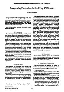
Figure 1. Calibration pattern with 4 IR leds on each corner
2. Calibrating Wii Remotes We describe the geometric calibration of two Wii Remotes, but extension to more Wii Remotes is trivial as they can be calibrated pair-wise starting from a reference one. In the next subsection, we briefly discuss the calibration of Wii Remotes using 4 IR LEDs and the popular calibration method of Zhang [2]. Then we describe our method that uses only two IR light sources.
2.1. Calibration using 4 points Given at least 3 views (without any constraints on the intrinsic parameters) of a known planar calibration plate, a camera can be calibrated [2]. This method uses planar homographies between the calibration plate and the image of the calibration plate, which gives two constraints on the 5 unknowns of the intrinsic parameters. With at least 3 views of the calibration plate, the intrinsic parameters of a camera is computed and the extrinsic parameters (rotation and translation between the camera and the calibration plates) are computed using the homographies. Since computing a homography, in general, requires 4 point correspondences, calibrating the Wii Remote is possible as it can view 4 points at the same time. To obtain reference values for the calibration, we implemented this method using a rectangular IR led structure on a board, see Fig. 1. Results of the calibration with 4 points are given in section 3. Calibrating the Wii Remotes using 4 points is a welldefined problem and easily solved using the method described above. The results of this method can be taken as the ground truth for our two point calibration method. Although this method is very successful, it is not suitable for the home environment for which the Nintendo Wii is designed, since it requires construction of the calibration plate with 4 carefully placed IR leds. In the following subsection, we define our two point calibration method for the Wii Remotes (Fig. 2).
2.2. Calibration using 2 points Given two cameras, for example two Wii Remotes, we define the intrinsic matrices of the cameras as K and K 0 ,
the rotation and translation between the two cameras as R and t, such that X2 = RX1 + t, where X1 and X2 are the same point in the reference frames of first and second camera, respectively. The camera matrices can be defined as P = K[I|0] and P 0 = K 0 [R|t] , (1) where the world reference frame is assumed to be same as the first camera reference frame. The Fundamental matrix is very important for our method. We compute the Fundamental matrix from the tracked image points. Establishing correspondences in our case is different from classical correspondence establishment. The Wii Remotes reports two points for each view as our calibration setup uses only two light sources. However, we do not know the correspondences between the points. Furthermore, there are no image features available to solve the correspondence ambiguity because Wii Remotes effectively report only the point coordinates. We developed a method to estimate the Fundamental matrix by assuming arbitrary point correspondences at the beginning. A wrongly matched pair will stand out after the computation of the Fundamental matrix. x0T F x = 0
(2)
Wrongly matched pairs are swapped and the Fundamental matrix is recomputed. Since we use the sensor bar, we have exactly two points in each view. For those points, we have 2 possible correspondence configurations for a given time frame. First, we choose the configuration for which the Euclidean distances are smallest and compute the Fundamental matrix. Next, for the wrongly matched points, we choose the second configuration by simply swapping the correspondences for the specific frame and recompute the Fundamental matrix. Wrongly matched points are easily found by checking them and their swapped configurations against the computed Fundamental matrix. We compute the Fundamental matrix once at the start of our method and the rest of the calibration procedure depends on the precision of the Fundamental matrix. Thus, we need to compute the
(a) Calibration using 4 points
(b) Calibration using 2 points (Sensor Bar)
Figure 2. Data gathering for Wii Remote calibration
Fundamental matrix very accurately. We use the nonlinear minimization of the geometric image distances to compute the Fundamental matrix. Details of this nonlinear method can be found in [5]. Our task is to find all the unknowns in Eq. 1, using only the images of a two point structure, such as the Sensor Bar. Our method mainly consists of two steps; stereo calibration and global refinement. We start with initial guesses for K and K 0 , and iterate these steps until convergence. 2.2.1
Stereo calibration given the Essential matrix
The Essential matrix can be directly computed using the intrinsic matrices of the first and second camera, K and K 0 respectively, and the Fundamental matrix F using the following formula. T
E = K 0 F K.
(3)
Geometrically the Essential matrix is defined as E = [t]× R.
(4)
Note that the Essential matrix is a projective entity and defined up to a scale. Thus, given E, t is computed such that ktk = 1. We find R and t from the Singular Value Decomposition of the Essential matrix [5]. The length of t is then computed using the known distance between two scene points. 2.2.2
Global refinement given the stereo calibration
The main realization of our method is that, as the Fundamental matrix is fixed (the image points are fixed), the reconstruction for a given K and K 0 is different from the true reconstruction only by a projective ambiguity since the Fundamental matrix encapsulates the projective properties of the reconstruction completely. Thus, the camera matrices P and P 0 computed using K and K 0 are related to the true
camera matrices P ∗ and P 0∗ with a projective transformation of the 3-space. P ∗ = P H and P 0∗ = P 0 H.
(5)
We are not interested in the Euclidian properties, except the scale, of the projective transformation H. Removing the global rotation and translation of the space, we fix the world reference frame to the frame of the first camera. Since H is a projective entity and invertible, we also set h44 = 1. Finally, H is in the form of h11 0 h13 0 0 h22 h23 0 . (6) H= 0 0 h33 0 h41 h42 h43 1 From the projective reconstruction theorem, we know that the points Xi , which are reconstructed using P and P 0 , are related to the true (Euclidian) reconstructed points Xi∗ by the inverse of H, Xi∗ = H −1 Xi .
(7)
We use Eq. 7 as the basis of our global refinement method. One can verify that H −1 has the same form as H. So we have basically 8 unknowns which can be solved given at least 8 constrains on H −1 . For the true reconstructed points we know that the 3D distance between two points Xi∗ and Yi∗ of the same time frame will be constant. One such point pair gives one constraint on H −1 [3], which can be written as kH −1 Xi − H −1 Yi k2 = D2 , (8) where D is the distance between Xi∗ and Yi∗ , ie. length of the Sensor Bar in our case. Given more than 8 images of the Sensor Bar, we compute H −1 with Levenberg-Marquardt method using the nonlinear least-squares formulation of Eq. 8. On convergence, we evaluate Eq. 5 and obtain new intrinsic matrices. This completes one iteration of our calibration method.
(a) One end of a lit Sensor Bar
(b) Sensor Bar covered with translu- (c) Sensor Bar covered with opaque cent material material
Figure 3. Covering Wii sensor bar. Upper-right images are taken with an IR camera.
2.2.3
Initialization
The initialization of our method requires only the intrinsic matrices K and K 0 since the stereo parameters are easily computed using the Essential matrix as described in the subsection 2.2.1. We initialize our method with an initial K and K 0 obtained from another source [8]. Using the method described in section 2.1 we observed that different Wii Remotes we have worked on share very similar intrinsic parameters with [8] and within themselves. This is an expected result as the Wii Remotes are fix focused and mass produced. So it is safe to assume that given a Wii Remote, its intrinsic parameters will be in the reasonable vicinity of the initial intrinsic parameters. 1306.3 0 535.0 ¯ = 0 1302.3 401.7 (9) K 0 0 1 The nonlinear minimization in the second part of our calibration method requires an initial guess of H −1 . As we ¯ we expect that H and in start with a very good estimate K, return H −1 will be very close to identity. Thus, we start the Levenberg-Marquardt iterations with H −1 = I. 2.2.4
Discussion
Since the effective resolution of the Wii Remotes comes from 8× subpixel processing of the image blobs, the tracked positions are quite noisy. This property can be observed by carefully tracing the positions of slowly moving multiple points on a rigid structure, such as the calibration plate or the Sensor Bar. The positions of the points will change not synchronously and not smoothly. To overcome this problem, one should gather large amounts of data assuming the noise will cancel out in the process. For example, nonlinear minimization in the second step of our method requires at least 8 views of the Sensor Bar, however, hundreds of views should be taken in order to succeed. 5-10 seconds of continuous capture was sufficient to produce hundreds of views. When using the Sensor Bar, the Wii Remote will report the merged positions of the clusters on each end of the Sensor Bar. When the Sensor Bar is not viewed directly, ie. the
Sensor Bar is not parallel to the image plane and it is not close to the principle axis of the camera, merged positions for only the visible LEDs will be reported. In general not all LEDs are always visible and the effective length of the Sensor Bar will be different for different orientations with respect to the Wii Remote. In order to overcome this difficulty, we have placed an opaque material around the Sensor Bar such that only one of the LEDs is visible. We also placed a translucent material, as a diffuser under the opaque material to be illuminated, so that the position of the light source will be the position of the hole on the opaque material under any viewing direction. Fig. 3 shows the lit Sensor Bar with the mentioned cover. The nonlinear minimization method used to compute H −1 in Eq. 8 requires some variance on the orientations and positions of the viewed calibration tool. However, any unfitness of the data can be easily detected as the nonlinear minimization will not give a solution. Another issue is that, the refined camera matrices obtained by evaluating Eq. 5 may lead to a reconstruction that has higher error on the measured Euclidian positions compared to previous reconstructions. This problem can also be detected by checking the reconstructed lengths of the Sensor Bar after each iteration. Regathering calibration data seems to solve this problem too. In our experiments, we could always gather suitable data for successful convergence without much difficulty.
3. Experiments We have performed several experiments to test the methods presented in this paper. The initial intrinsic matrix for the Wii Remotes is obtained as discussed in Section 2.2.3 and is given in Eq. 9. The initial intrinsic matrix was borrowed from another source [8]. We give the 4 point calibration results for one of the Wii Remotes we had as 1319.29391 0 K= 0
0 1331.90309 0
450.20574 409.00600 1
(10)
We give the calibration results for the same Wii Remote
Figure 4. Synthetic data generation to simulate a sensor bar Table 1. Comparative results based on reconstruction error (mean / std)
Method 4 points rectangle Eq. 9, initial K 2 points covered 2 points uncovered 2 points synthetic 2 points visible
Fundamental matrix error (px) 1.24862 / 1.14431 -/1.50889 / 1.34572 1.72998 / 1.41599 ˜1 / ˜1 0.32338 / 0.28736
as in Eq. 10 using the Sensor Bar as the calibration tool. 1345.68537 0 K= 0
0 1313.03408 0
482.35358 422.45015 1
(11)
The calibration result for another is given below, which also hints that although the focal lengths of the Wii Remotes are quite similar, the principle points may vary dramatically. However, this is not a big problem in terms of reconstruction error. 1344.37502 0 K= 0
0 1345.35070 0
449.48667 350.07932 1
(12)
To test our method further, we generated synthetic cameras and synthetic data to simulate the sensor bar calibration (Fig 4), for which we know the ground-truth calibration results. The length of the synthetic sensor bar is set to 20cm which is also the length of the Wii sensor bar (distance between middle LEDs). To be realistic, we applied noise to the generated synthetic image data. The amount of noise is defined via the error of the Fundamental matrix computed for the generated image points. We added noise such that the mean and variance of the error of Fundamental matrix would both be roughly 1 pixel. We present the accuracy of our algorithm in terms of reconstruction error, which is measured as the difference of
Reconstruction error (cm) -/-/0.65695 / 0.62520 1.31312 / 1.35218 0.59894 / 1.13388 0.62019 / 1.06964
Test error (cm) 0.57440 / 0.64420 4.41542 / 3.13076 1.01446 / 1.09935 1.88319 / 1.38885 1.65816 / 1.37329 1.47778 / 1.62526
the reconstructed length of the sensor bar from the groundtruth length (20cm). We summarize our results in Table 1. The results are computed over several experiments for each case and the mean and standard deviation of the respective values are presented as a table. We also emphasize the importance of the accuracy of the Fundamental matrix, as our algorithm is based on image measurements and better image measurements leads to more accurate Fundamental matrices and more accurate reconstructions. The second column in Table 1 gives the image error for the computed Fundamental matrices. The third and fourth columns of Table 1 give the reconstruction error for the computed bar lengths. The Reconstruction error is the final error minimized by our method given the image measurements. The Test error, on the other hand, measures the accuracy of the calibration parameters from our method by testing them on data that was not present in the minimization. The results clearly show that the average intrinsic matrix is refined to a level where the reconstruction error is acceptable for 3D measurement applications. To further test our refinement method, we have performed some experiments with visible light cameras. We used two Basler Scout cameras which have 640x480 resolution. We imaged the standard calibration (chessboard) pattern from various positions and angles, and constructed bar-like inputs using the diagonals of the viewed pattern. We have initialized the refinement for visible light cameras with the intrinsic matrices that are slightly perturbed from the true intrinsic matrices, which are computed using [2].
Figure 5. Two players playing a game in front of the Wii Remotes
We give the results and error measurements of the visible light cameras in the last line of Table 1. We also implemented a 3D demo game to test the usability of the calibration with two points. In the demo game the players use a single IR led to move a ball through a pipe network in the 3D space. The absolute position of the IR LEDs are calculated using an optimal triangulation [4] method off the data from the Wii Remotes. The player tries to move the ball inside the pipes while trying not to touch the pipes. In Fig. 5 we give a screenshot from our application along with the actual players playing the game in front of the two Wii Remote setup. Our application, built using only two Wii Remotes, can take up to 4 inputs since the Wii Remotes can report up to 4 points. Note that, our game takes absolute 3D positions from the game player, which was not possible without Wii Remote calibration.
4. Conclusions We have presented a method for calibrating multiple Wii Remotes using only the Sensor Bar. We have exploited the fact that an almost Euclidian reconstruction can be refined using Euclidian constraints and our novel iterative calibration method. We also exploited the fact that Wii Remotes are mass produced and they have similar intrinsic parameters which lets us initiate our method with a very good starting point. For average Wii Remote users, our method does not require any additional hardware for the calibration. One only needs two Wii Remotes, a PC and a calibration bar. The Sensor Bar that comes with the Wii Console or two arbitrarily placed IR leds can be used as the calibration bar. The success of our method depends on a lot of details about the data gathering and implementation. The collected data using the Sensor Bar must have enough variance to apply the Euclidian constraint on the bar length. However, unfitness of the data can easily be detected and data gathering can be redone. The implementation of the method must use powerful techniques for intermediate steps such as computing the Fundamental matrix, triangulation and computing
the projective transformation of the 3-space. We assumed that the Wii Remotes follow a projective camera model that generates images using central projection. Thus, our method can readily be used to calibrate visible light cameras given the care for data gathering and implementation, which we have shown in Section 3. On the other hand, our method is not, in its current state, suitable for arbitrary camera calibration without any guess on the intrinsic parameters. Our future work includes exploring the possibilities to improve our method for arbitrary camera calibration. One possible way would be cleverly searching the entire 8 dimensional space for the two intrinsic matrices.
References [1] Johnny Chung Lee. Hacking the Nintendo Wii Remote IEEE Pervasive Computing, vol. 7, no. 3, pp. 39-45, 2008. [2] Zhengyou Zhang. A Flexible New Technique for Camera Calibration Technical Report, 1988. 1, 2, 5 [3] Boufama B., Mohr R., Veillon F. Euclidean constraints for uncalibrated reconstruction Fourth International Conference on Computer Vision, Proceedings., 1993. 3 [4] Hartley R and Sturm P Triangulation Computer Analysis of Images and Patterns, 1994. 6 [5] Hartley, R. I. and Zisserman, A. Multiple View Geometry in Computer Vision Cambridge University Press, ISBN: 0521623049, 2000. 3 [6] Nintendo Wii Remote http://www.nintendo.com/wii/console/controllers, 2006 1 [7] WiiCommunity Wii Remote Technical Specifications http://www.wiibrew.org/wiki/Wiimote, 2010 1 [8] Simon Hay, Joseph Newman and Robert Harle Optical tracking using commodity hardware Proceedings of the 7th IEEE/ACM International Symposium on Mixed and Augmented Reality, 2008 1, 4