FPGA with user-defined SBs. In the second version [7], given a certain segment length, we found the optimal combination of SBs in terms of Delay, Energy, Area, ...
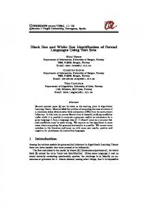
WIRE SEGMENT LENGTH AND SWITCH BOX CO-OPTIMIZATION FOR FPGA ARCHITECTURES Kostas Siozios and Dimitrios Soudris VLSI Design and Testing Center, Department of Electrical and Computer Engineering Democritus University of Thrace, 67100, Xanthi, Greece email: {ksiop, dsoudris}@ee.duth.gr ABSTRACT The novel methodology for designing a high-performance and low-energy FPGA interconnection architecture consisting of appropriate wire segments and multiple Switch Boxes is introduced. Depending on the localized performance and energy consumption requirements of each specific region of FPGA architecture, we derive a set of corresponding spatial routing information of the applications mapped onto reconfigurable device. In this paper, an interconnection network with segments L1&L2 and 3 different Switch Box regions is used. The selection criterion for our approach is the minimal Energy×Delay Product (EDP). The proposed methodology is fullysupported by the software tool called EX-VPR. With this interconnection architecture we achieved EDP reduction by 56%, performance increase by 47%, reduction in leakage power by 18%, reduction in total energy consumption by 9%, at the expense of increase of channel width by 15% compared to conventional FPGA architectures. 1. INTRODUCTION Due to the fact that about 70-90% of typical an FPGA is occupied by routing resources [4], many researchers have spent much effort on minimizing the energy consumption [1], [5] and on achieving higher frequencies. Indeed, a typical FPGA routing architecture uses about 70-90% of the total transistors on the die [4], which apparently has large impact not only on the total energy consumption but also on the performance of an FPGA device. A typical interconnection network of FPGA consists of the wire segments and the Switch Boxes (SBs). Due to the fact that the dynamic power dissipation is proportional to the wire interconnection capacitance and the wires have more capacitance compared to SBs, the proposed methodology targets first to minimize the impact of segments to the total power and secondly to minimize the capacitance associated with SBs. This work was partially supported by the project IST-34793AMDREL, the project PENED 03ED593 and the project PYTHAGORAS II which are funded by the European Commission and the GSRT of Ministry of Development
c 1-4244-0 312-X/06/$20.00 2006 IEEE.
The last two years, different versions of EX-VPR have been presented. In particular, the research work of [2] extended the VPR tool features to support homogeneous FPGA with user-defined SBs. In the second version [7], given a certain segment length, we found the optimal combination of SBs in terms of Delay, Energy, Area, and EDP. In [8], after the selection of the optimal combination of SBs based on an application’s interconnection requirements, we replaced some transistors from SBs with hard-wired connections. In this paper, we propose a novel methodology for designing a high-performance and low-energy interconnection structure of an island style-based FPGA platform. The main goal is to find out the appropriate segment length as well as the associated optimal combination of multiple SBs. The efficiency of a wire segment and SB is characterized by analyzing parameters such as energy dissipation and performance. We made an exhaustive exploration with all the kinds of MCNC benchmarks, to find out both the optimal segment length for minimizing the EDP of a conventional FPGA, as well as the optimal combination among three well-known academic SBs, i.e. Wilton [1], Universal [1] and Subset [1], assuming the selected segment. The interconnection network for the reconfigurable device is consisted of segments L1&L2 and 3 regions of different SBs. 2. THE DESIGN METHODOLOGY FOR FPGA INTERCONNECTION ARCHITECTURE The proposed methodology for determining the optimal interconnection architecture consisted of three steps (Fig.1). The methodology is software-supported by a new tool named EX-VPR [2], while for evaluation purposes MCNC benchmarks and XC4000 FPGA architecture [3] are used. The first step of the methodology is to find out the connectivity, the performance, the energy consumption and the area requirements of MCNC benchmarks. Particularly, by the term connectivity we define the total number of active connections, i.e. the “ON” pass-transistors, which take place into a SB. A specific map (or set of curves) can be created for each aforementioned design parameter,
which shows the parameter variation across (X,Y)-plane of the whole FPGA device. Fig. 2 shows the average connectivity values for all the MCNC benchmarks, in normalized manner. It can be seen that the connectivity varies from point to point of FPGA and the number of used pass-transistors (i.e. ‘ON’ connections) decreases gradually from the center of FPGA architecture to the I/O blocks. The connectivity requirement for more tracks in the center of the device, compared to the borders depends on the chosen routing algorithm [2] and therefore, the interconnection resources are not utilized uniformly over any (x,y) point of FPGA. Consequently, the challenge which should be tackled by a designer is to choose only the needed hardware routing resources, considering the associated spatial information from the connectivity distribution graph.
DSP). For that purpose, we propose a piecewisehomogeneous FPGA architecture consisting of a few piecewise regions. Considering a certain threshold of the connectivity value Cth, and projecting the 3-D diagram to (X,Y) plane of FPGA, we can create maps which depict the corresponding connectivity requirements. Assuming Cth=3, Fig. 3 shows the connectivity requirements of MCNC applications mapped on conventional FPGAs. By increasing the threshold value Cth, the FPGA becomes more heterogeneous, as it is consisted by more regions. On the other hand, this increase leads to performance improvement for the device, due to the better routing resources utilization.
Fig. 3.
Fig. 1.
Methodology for selecting optimal interconnection network
Fig. 2.
Overall connectivity across the whole FPGA
Although a conventional FPGA architecture is a homogeneous and regular one (i.e. just repeation of tile blocks), the actually-used hardware resources provide a non-homogeneous and irregular picture. Ideally, we had to use different interconnection architecture at each (x,y) point of FPGA, which would lead to a totally irregular FPGA architecture increasing, among others, NRE fabrication costs. However, such “extreme” architecture is the optimum solution for application on a specific FPGA implementations architecture, but apparently it is not a practical and cost-effective implementations for any application or at least, for a class of applications (e.g.
Connectivity requirements for three regions
The proposed technique takes into account the number of the utilized pass-transistors of SBs in the various regions of FPGA map (Fig. 3). Thus, in regions with smaller connectivity (i.e. fewer “ON” transistors) we can use the appropriate type of SB, which can function with less number of transistors and therefore, we result into reduced energy consumption. The connectivity degree of (x,y) point of FPGA array is straightforward-related with the energy consumption of (x,y) SB location, since less number of active SB connections means smaller capacitance and thus, less energy consumption. Determining the “hot spots” locations of FPGA device, the designer can concentrate his/her efforts for the reducing energy consumption on certain regions only, but not on the whole device, reducing the design-time costs and alleviating the time-to-market pressure. Furthermore, increasing (or reducing) the number of distinct regions, the designer can specify in more (or less) detailed manner the spatial distribution of energy consumption and therefore, he/she can choose the most appropriate SB for each region at the expense of the increased heterogeneity of FPGA architecture. On the other hand, this has a penalty at the fabrication cost of the device. Throughout the paper, we choose Cth=3. 2.1. Segment Length Exploration The second step of the proposed methodology is to determine the most appropriate wire length of a
homogeneous (conventional) FPGA, (considering XC4000 SB). Fig. 4 plots the average value over all benchmarks, for a number of design parameters. The horizontal axis represents the length of the wire segments, while the vertical one is the normalized value for a design parameter. As it is mentioned, the selection of the optimal segment length is based on EDP criterion. It can be seen that the segment L1&L2 provides the minimal EDP. All the benchmarks that used for exploration results are placed and routed into optimal square FPGA devices with minimal channel width. These constraints imply that for some small variations of SB ratios, we may have large variations of the corresponding required area. As the routing algorithm tries to find out the optimal channel width, it uses a more stressed approach. By varying the ratio between the SBs regions, we modify the available routing resources. The routing algorithm is aware about the FPGA interconnection and has impact on the performance, energy dissipation and area of the device. 1,00 0,90 0,80 0,70 0,60 0,50 0,40 0,30 0,20 L1
L1&L2
L1&L4
L1&L8
Delay
Fig. 4.
Leakage
L2
L2&L4
L2&L8
:4
Energy
L4&L8
L8 EDP
Design parameters variation for different segment lengths
corners of the device (Region1) there is no need for high connectivity, as it shown in Fig. 2. So, a low performance and low-energy SB (Subset) is chosen. Additional SBs (Wilton and Universal) have to be placed into the rest device (Region2 and Region3).
Fig. 5.
SBs assignment into three regions
Fig. 6 shows the exploration results for EDP for the two possible combinations of SB topologies and ratios. For instance, the number “60” of the curve “UniversalWilton”, shows that the percentage of “Universal” SB into the FPGA array is 60%, while “Wilton” SB occupies the 40% of the total number of SBs. Moreover, having a combination SB _ Type_ Re gion3 and SB _ Type_ Re gion2 , we assign the foregoing SB to the orthogonal located in the center of FPGA (Region3), while the latter SB is assigned to the remaining part of FPGA (Region2) without the corners. We can deduct that the ratio 60%/40% of “Universal-Wilton” combination, minimizes the EDP value. The Universal SB is assigned to Region2, while Wilton SB to Region3. Energy-Delay Product 1,0 0,9
2.2. Switch Boxes Combination Exploration Employing the spatial information regarding with a SB location, this section provides detailed data about the selection procedure of the optimal combination of SBs, with respect to the design parameters (EDP, energy consumption, delay, area, etc). Assuming three distinct regions (Fig. 5), each of which uses a different type of SB, we performed exploration for all possible values, of SB_ratio’s: SB _ ratioi =
SB _ Type _ Re gioni 3
∑ (SB _ Type _ Re gion )
(1)
i
i =2
where SB_Type_Regioni denotes the number SBs of Regioni. In order to determine the SB type and the SB_ratio, which composes the proposed interconnection architecture, we map all existing MCNC benchmarks to the smallest square FPGA. We performed design exploration for the main design parameters (EDP, performance, leakage power, energy consumption and area). Due to lack of space we show only results for the EDP criterion. At the
Normalized Values
0,8 0,7 0,6 0,5 0,4 0,3 0,2 0,1 0,0 7
13 19 25 31 36 41 46 51 56 60 64
68 72 75 78 81 84 87 89 91 93 95 96 97 98 99 100 SB Ratio (%)
UNIVERSAL_WILTON
Fig. 6.
WILTON_UNIVERSAL
FPGA Energy×Delay Product (EDP)
All the benchmarks that used for exploration results are placed and routed into optimal square FPGA devices with minimal channel width. These constraints imply that for some small variations of SB ratios, we may have large variations of the corresponding required area. As the routing algorithm tries to find out the optimal channel width, it uses a more stressed approach. By varying the ratio between the SBs regions, we modify the available routing resources. The routing algorithm is aware about the FPGA interconnection and has impact on the performance, energy dissipation and area of the device.
The main reason, we chose the three SBs (Wilton, Universal and Subset) for our exploration process, was the fact these SBs are widely-used and they can be supported by the EX-VPR tool [2].
30
25
nsec
20
15
10
3. EXPERIMENTAL RESULTS
5
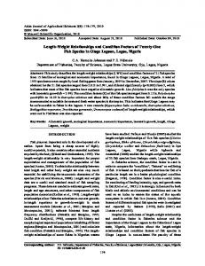
The proposed interconnection architecture was implemented and tested by the largest MCNC benchmarks. These benchmarks were placed and routed in an islandstyle FPGA array [6], [3] using the EX-VPR tool. Fig. 7 shows comparison results for EDP of conventional FPGA architecture (XC4000), one with multiple SBs and segment L1 and the proposed one (multiple SBs and segment L1&L2). Since our primary goal is the design of both high performance and low-energy FPGA architecture, we choose the optimal EDP value from the exploration results (Fig. 6). Comparing the results with conventional architectures, and interconnection schemes composed by segment L1 and Multi-SB, the proposed one minimizes the delay up to 47%. In addition to that, it gives promising results both for the leakage power, as well as the total energy consumption. More specifically, the gains in leakage power are up to 18%, while the energy requirements reduced about 9% in average compared to conventional FPGA architectures. It should be stressed that we achieved to design a high performance interconnection architecture, without any negative impact on leakage or total energy, although high performance circuit implies high switching activity and eventually, increased energy.
0 big
y ke
a clm
ic ipt ell
10 10 ex
sc fri
L1 + Multi-SB
Fig. 8.
c pd
98 s2
17 84 s3
84 85 s3
q se
la sp
L4 + Multi-SB
Delay for XC4000 and proposed interconnection architecture
4. CONCLUSIONS A novel FPGA interconnection methodology for high speed and energy efficient island-style FPGA architectures was presented. Using appropriately, the spatial information of various FPGA parameters, a new routing architecture with multiple-SBs and segment length L1&L2 was designed. Using the minimal EDP value, the comparison results proved that heterogeneous FPGA platform outperforms with a conventional FPGA. Furthermore, the design of the new FPGA architecture is fully softwaresupported approach. 5. REFERENCES G.Varghese,J.M.Rabaey, “Low-Energy FPGAs-Architecture and Design”, Kluwer Academic Publishers, 2001
[1] 50,00 45,00
K. Siozios, et.al., “An Integrated Framework for Architecture Level Exploration of Reconfigurable Platform”, in Proc. of 15th Int. Conf. FPL, pp 658-661, 2005
[2]
40,00 35,00 30,00 25,00
“Survey of existing fine-grain reconfigurable hardware platforms”, Deliverable Report D9 for AMDREL project, available at http://vlsi.ee.duth.gr/amdrel/pdf/d9_final.pdf
[3]
20,00 15,00 10,00 5,00
Conventional
L1 + Multi-SB
sp la
se q
s3 85 84
s3 84 17
s2 98
pd c
c fris
ex 10 10
tic el lip
big ke y
clm a
0,00
L1&L2 + Multi-SB
Comparison among conventional interconnection (XC4000), L1+Multi-SB and the proposed one (L1&L2+Multi-SB) in term of EDP
Fig. 7.
Fig.8 shows the performance gain of the proposed interconnection architecture compared to the conventional one. It can be seen that the proposed method achieved significant reduction in delay of about 47% in average. Comparing the required number of routing tracks for successful routing procedure, we conclude that the proposed methodology needs about 15% wider channel comparing to conventional FPGA architectures.
A. Dehon, “Balancing interconnect and computation in a reconfigurable computing array (or, why you don’t really want 100% LUT utilization), Int. Symp. on FPGAs, pp. 69-78, 1999
[4]
K. Poon, A. Yan, S. Wilton, “A Flexible Power Model for FPGAs”, in Proc. of 15th Int. Conf. FPL, pp.312–321, 2002
[5] [6]
http://vlsi.ee.duth.gr/amdrel
K. Siozios, D. Soudris and A. Thanailakis, “A Novel Methodology for Designing High-Performance and Low-Power FPGA Interconnection Targeting DSP Applications”, in Proc. of Int. Symp. on Circuits and Systems, 2006, Greece
[7]
K. Siozios, et.al, “Platform-based FPGA Architecture: Designing High-Performance and Low-Power Routing Structure for Realizing DSP Applications”, in Proc. of 13th RAW, 2006
[8]