LODEWIJK VAN HOESEL, TIM NIEBERG, JIAN WU, AND PAUL J. M. HAVINGA. UNIVERSITY OF ... Authorized licensed use limited to: UNIVERSITEIT TWENTE. ...... [1] R. D. Hof, âThe Quest for the Next Big Thing,â Business. Week, Aug.
To increase the data rate, EDGE employs 8-PSK with a linearized GMSK ..... ters are amenable to adaptive implementations, and may more drastically ..... spaceâtime coding and signal processing, OFDM, and digital subscriber line technology ...
[1] W. Leland, M. Taqqu, W. Willinger, and D. Wilson, âOn the self-similar nature of ... [2] J. Beran, R. Sherman, M. Taqqu, and W. Willinger, âLong-range depen-.
Aug 1, 1999 - I. INTRODUCTION. ADSL (asymmetric digital subscriber line) [1], DAB (dig- ... The authors are with the Department of Electronic and Informa-.
AbstractâIn this letter, we give a tight approximation for the bit-error rate (BER) of decision-feedback differential detection. (DF-DD). The influence of error ...
IEEE Wireless Communications ⢠August 2004. 76 ... less multimedia services to mobile/wireless IP- ..... ways, MIDCOM protocol, and SDP extensions for NAT.
Automotive telematics enables the deployment of a num- ber of new services and applications integrating wireless communication technology into a vehicle.
Dec 23, 2009 - Engineering, University of Victoria, Victoria, BC V8W 3P6, Canada. Publisher Item Identifier ..... New York: Dover, 1972. [11] E. Biglieri, G. Caire, ...
t is well known that a technology becomes ... In common with ather systems, the technology growth ... The articles in this special issue cover three user scenar-.
mart homes link computers to every- ... A smart home assumes wntrol of devices and coordinates ... physical layer protocols can support delay-sensitive data.
IEEE TRANSACTIONS ON COMMUNICATIONS, VOL. 43, NO. 2/3/4, FEBRUAKY/MARCH/APRIL 1995. 70 I. Multi-Stage Blind Clustering Equaliser. S. Chen, S.
[10] T. A. Perkins, N. de N. Donaldson, A. C. Worley, V. Harper, D. E.. Wood, and D. N. ... Michael J. Dolan, Brian J. Andrews, and Peter H. Veltink. AbstractâA ...
George Bebis, Member, IEEE, Sushil Louis, Yaakov Varol, and Angelo Yfantis. AbstractâWe ...... [22] G. Bebis, M. Georgiopoulos, M. Shah, and N. d. V. Lobo, â ...
capital; for the societal perspective, we used a lower rate, which approximates a social discount rate. For the NPC case study, we used 15.07% as the discount ...
M. S. Bright was with the School of Engineering, Cardiff University, Cardiff. CF24 0YF, Wales, U.K. He is now with the Broadcom Corporation, Bristol. BS16 1EJ ...
Chung-Shi Tseng, Member, IEEE, Bor-Sen Chen, Senior Member, IEEE, and ... of Ming Hsin Institute of Technology, 30401, Hsin Feng, Hsin Chu, Taiwan,.
The Ohio State University. Columbus, OH 43210. Abstract: This paper presents a methodology for implementing artificial neural network (ANN) observers in ...
respect to fizz, 2;' Hzl, z;'] to prove that ker G is non- trivial. When G is LFP (but not ..... Let 6, = max{lil + ljl:(HT, zizi) # O}, 6, = max{(lil. + I jl: (W, zfzi) # O}, and 6 = 6 ...
[2] R. P. Gooch and J. J. Shynk, âWide-band adaptive array processing using pole-zero digital filters,â IEEE Trans. Antennas Propagat., vol. AP-34, pp. 355â367 ...
failure classes FAI, FA(^^-^), FA"* are also defined similarly, and. : = {diag [fl ... fnz] I ..... If p E M(Ru), then DP, DP, Ysk, Msk, YAm, MAm can be taken as identity ...
A 3-kW induction motor experimental system with digital ... high sampling frequency needed for digital implementa- .... nonzero vectors used for illustration). ..... elled widely and has given keynote addresses, tutorials, and invited lectures to.
Manuscript received April 4, 2000; revised February 14, 2001. This work was supported by the Office of Naval Research under Grant N00014-00-1-0141.
veloped by S. Ufer at the BMMSL [5]) were used. Both ion-selective electrodes ... location of the ground plane/conductors and can only be taken as estimates.
IEEE TRANSACTIONS ON POWER ELECTRONICS, VOL. 14, NO. 1, JANUARY 1999. 177. A Three-Switch High-Voltage Converter. Dongyan Zhou, Member ...
John Thornton, David Grace, Member, IEEE, Myles H. Capstick, and Tim C. Tozer, Member, IEEE. AbstractâIn a wireless communications network served by a.
484
IEEE TRANSACTIONS ON WIRELESS COMMUNICATIONS, VOL. 2, NO. 3, MAY 2003
Optimizing an Array of Antennas for Cellular Coverage From a High Altitude Platform John Thornton, David Grace, Member, IEEE, Myles H. Capstick, and Tim C. Tozer, Member, IEEE
Abstract—In a wireless communications network served by a high altitude platform (HAP) the cochannel interference is a function of the antenna beamwidth, angular separation and sidelobe level. At the millimeter wave frequencies proposed for HAPs, an array of aperture type antennas on the platform is a practicable solution for serving the cells. We present a method for predicting cochannel interference based on curve-fit approximations for radiation patterns of elliptic beams which illuminate cell edges with optimum power, and a means of estimating optimum beamwidths for each cell of a regular hexagonal layout. The method is then applied to a 121 cell architecture. Where sidelobes are modeled as a flat floor at 40-dB below peak directivity, a cell cluster size of four yields carrier-to-interference ratios (CIRs), which vary from 15 dB at cell edges to 27 dB at cell centers. On adopting a cluster size of seven, these figures increase, respectively, to 19 and 30 dB. On reducing the sidelobe level, the improvement in CIR can be quantified. The method also readily allows for regions of overlapping channel coverage to be shown. Index Terms—Antenna sidelobes, cellular communications network, cochannel interference, elliptic beams, frequency reuse, high altitude platforms (HAP), microwave antenna array.
I. INTRODUCTION
W
ITH AN ever increasing demand for capacity for future generation multimedia applications, service providers are looking toward the millimetric wave bands. One possible means of their exploitation is the use of high altitude platforms (HAPs) [1]–[7], which operate in the stratosphere, at an altitude of 17—22 km. HAPs have the potential to provide line-of-sight links to a large number of users, situated over a large geographical area, and using considerably less communications infrastructure than that required if delivered by a terrestrial network. Such systems will employ a cellular architecture in order to provide overall system capacity, with cells served by a number of antenna spot beams from the HAP. The performance of terrestrial cellular architectures has been described by Lee in 1989 [8]. To provide wide coverage the cells are tessellated, with different channels assigned to neighboring cells in order to manage cochannel interference; assignments can take the form of frequencies, time slots, or codes. Conventionally, cells are clustered into groups of three, four, seven, or nine, dividing the overall frequency allocation between them.
Manuscript received May 22, 2001; revised October 23, 2001; accepted February 15, 2002. The editor coordinating the review of this paper and approving it for publication is R. A. Valenzuela. This work was supported in part by the HeliNet project under IST-1999-11214 part of the EU 5th Framework Initiative. The authors are with the Department of Electronics, University of York, Helsington, York, Yorkshire YO10 5DD, U.K. (e-mail: [email protected]; [email protected]; [email protected]; [email protected]). Digital Object Identifier 10.1109/TWC.2003.811052
The larger the number of cells in the cluster, the greater the reuse distance and the higher the carrier to interference ratio (CIR), but the fewer the number of channels per cell; this tradeoff is fundamental to most cellular systems. Fixed channel assignment has been shown to produce the highest capacities in nonshadowed environments, but when the traffic load per cell varies, dynamic channel assignment has been shown to provide higher capacity [9]–[11]. Dynamic channel assignment is also particularly useful when the environment and/or traffic load is hard to predict [12]–[14]. A HAP cellular system has both similarities and differences with a terrestrial system. Reuse plans are still applicable (either fixed or dynamic), but an important difference is the way the interference arises and how it decays with distance. In a HAP system, interference is caused by antennas serving cells on the same channel and arises from overlapping main lobes or sidelobes. This paper will show how the number of antennas sharing a channel determines the CIR distribution on the ground. The ideal antenna beam illuminates its corresponding cell with uniform power across the cell and with zero power falling outside the cell—in this respect the antenna is acting as a spatial filter. In practice, the spot beams which are realizable fall short of this ideal, particularly at millimeter-wave frequencies, where array beam synthesis techniques are difficult. The most practicable antennas for this application are likely to be aperture types, whose radiation characteristics are well established. To minimize interference, beams with very low sidelobes and a steep roll-off in the main lobe are highly advantageous. While sidelobe suppression may be achieved with corrugated horn designs [15], the rate of roll-off is primarily influenced by the main lobe width and, hence, directivity. If too high a directivity is chosen, the cell will suffer excessive power roll-off at its edge; if too low a directivity is chosen, excessive power will fall outside the cell. At the frequencies allocated for HAPs, such as 48 GHz, limited available transmit power combined with rain fade gives rise to marginal link budgets particularly at cell edges. In this work, we present a general formulation for optimum directivity based on maximizing power at each cell edge, which is in contrast to similar work [3], [16], where the cell is defined as being within the footprint of the half-power beamwidth. In addition, software tools have been developed to predict the CIR across all cells on the ground, for a number of cellular topologies and channel reuse schemes. To facilitate this study, a computationally straightforward model for antenna beam patterns is described in Section II. This is followed in Section III by a method for calculating the required beamwidths and pointing angles for a conventional layout of equal size hexagonal cells, which is extended to calculate power and CIR
THORNTON et al.: OPTIMIZING AN ARRAY OF ANTENNAS FOR CELLULAR COVERAGE FROM A HIGH ALTITUDE PLATFORM
485
hence, the directivity may be expressed as a function of and only (6)
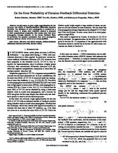
at the cell edge by fixing and We may now set varying . For example, Fig. 2 shows that for a given angle subtended at the cell edge, the directivity is maximized for a single value of . The cell geometry is shown in Fig. 5. As the angle subtended increases, the edge of cell (EOC) directivity is maximized for lower values of . The value of may be to zero, where is the derived by setting the derivative partial derivative with respect to
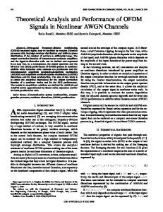
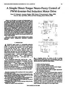
Fig. 1. Curve fit for typical corrugated horn radiation pattern.
levels on the ground. Our intention is, thus, to model a system of many antenna beams by using simple building blocks. The results, in Section IV, show how the geographical coverage can be expressed, and the effects of different sidelobe levels and cell cluster size may be readily compared. II. MATHEMATICAL MODELS FOR ANTENNA BEAMS Aperture antennas of medium and high directivity ( ) have main lobe patterns which may conveniently be approximated by a cosine function raised to a power [17] (1) where is the angle with respect to antenna boresight, and is chosen to define the rate of roll-off of the pattern. For example, Fig. 1 shows a typical corrugated horn radiation pattern and a curve fit of this type. The fit is very good in the main lobe until the directivity falls to 26 dB of it peak value. Beyond this, while the curve fit does not reproduce the sidelobe structure, a flat sidelobe floor may be fixed for modeling purposes (such a floor is usually specified by manufacturers [18]). When sidelobe levels are very low, such as in the above example, peak directivity is often approximated by [19] (2) and are the 3-dB beamwidths in two orthogwhere onal planes. These values are equal for a circularly symmetric beam, where (1) can be rewritten (3) The 3-dB beamwidth is also a function of . Since the directivity here falls to half its maximum value, we have (4) and so (5)
(7)
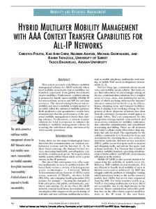
Thus, the curve fit method used is a convenient way of choosing the optimum edge of cell directivity as a function of a single parameter . For example, from Fig. 2, we can see that to maximize the power at the edge of a cell subtending 10 at the HAP, we choose . The antenna may then be chosen by deriving a value of the peak directivity using (2). To compare the beam pattern for the maximum EOC condition with suboptimum beams, Fig. 3 shows three cases, where the cell edge subtends 9 at the HAP. In Fig. 3, we see that fitting the 3-dB antenna beamwidth to the cell edge produces a directivity at the cell edge very similar to the maximum case, but the roll-off is worse. For the 10-dB fit, the improved roll-off would result in potentially less interference in neighboring cells (depending on their angular separation), but at the expense of a reduced link budget at the cell edge. In a more general formulation, the cell will subtend different angles in elevation and azimuth, and two orthogonal beamwidths may be derived to yield an elliptic beam which optimists EOC power in both planes. Techniques for producing elliptic beam antennas for optimizing geographical coverage are also discussed in [20]. While the effect on CIR is presented below, it should be reiterated that beamwidths other than those derived using the above method will yield a worse link budget at the edge of the cell. III. EFFICIENT ALGORITHMS FOR PREDICTING COCHANNEL INTERFERENCE As part of the HeliNet programmed [21], [22], software tools have been developed to quantify interference patterns in HAP cellular architectures. The HeliNet project proposes a variety of communications applications for a solar powered stratospheric aircraft, including broadband services at millimeter wave frequencies. Power and payload considerations are likely to limit the number of antennas, and hence cells, to between 100 and 200. This is partly due to the rapidly increasing total aperture area required when cell sizes are reduced, since more cells (and
486
IEEE TRANSACTIONS ON WIRELESS COMMUNICATIONS, VOL. 2, NO. 3, MAY 2003
Fig. 2. Directivity at edge of cell. (a) Directivity versus n. (b) Derivative versus n.
where is the width of the hexagon shown in Fig. 4, is the HAP height and the ground distance from the cell center to the subplatform point is derived from the cosine rule
(10) Since the results are repeated for each side of the hexagonal ring, the counter is used to identify the cell’s location with respect to the first cell along the side (11)
Fig. 3.
is an integer between one and six identifying the side where of the hexagon
Example curve fits for cell edge subtending 9 at HAP.
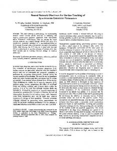
hence antennas) are needed, and each antenna becomes more directive and, hence, of greater aperture area. We anticipate that the HeliNet payload will be limited to a total aperture area which may be as low as 1 m [22]. For the cells sharing a given channel, the antenna pointing angles are first calculated and the azimuth and elevation angles subtended by each cell may be used to derive optimum elliptic beams using the above method. The angles must be derived as a function of the HAP height. To this end, the cells’ coordinates , where specifies the number of the are expressed as the number of the cell within concentric hexagonal ring and the ring. The convention is illustrated in Fig. 4, which also shows cells along the first side of the fourth ring by way of example. The elevation and azimuth pointing angles and from the HAP to the center of any cell may then be derived from
Floor
is an operator which rounds down to an integer. The and elevation and azimuth angles subtended by the circle of radius , which encloses the cell are illustrated in Fig. 5 and given by (13) and (14)
is calculated for The power at each point on the ground each antenna beam by deriving the elevation and azimuth angles and relative to boresight in antenna polar coordinates. A rotation through cell pointing azimuth is first applied
(8) and
(12)
(15) and
(9)
(16)
THORNTON et al.: OPTIMIZING AN ARRAY OF ANTENNAS FOR CELLULAR COVERAGE FROM A HIGH ALTITUDE PLATFORM
Fig. 4.
487
Coordinate system for hexagonal cell layout. (Inset: 121 cell layout.)
Fig. 5. HAP and cell geometry.
Fig. 6. Derivation of antenna directivity at a point on the ground. (Inset: in plane normal to boresight.)
then (17) and (18)
and only, and may hence be rapidly generated on changing and be the indices HAP height or cell width . Let for the curve fits of the form in (1) for an elliptic beam, fitted to and , respectively. optimize directivity at the cell edges is Then, the directivity seen at (20)
is the displacement transformed to a plane normal where to and centered on antenna boresight, as shown in Fig. 6
where
(19) The pointing angles and subtended angles for each cell are, and dimensions thus, a function of cell coordinates
(21)
488
IEEE TRANSACTIONS ON WIRELESS COMMUNICATIONS, VOL. 2, NO. 3, MAY 2003
Thus, for each beam, a data array is generated of the form where is derived from the antenna on the ground, minus the directivity seen at a point excess free space loss with respect to the subplatform point. (While CIR is not a function of free space loss, it is useful to include the term in the derivation of power so that the variation in power across the service area is properly scaled, as shown in Fig. 14.) Depending on the required spatial resolution, data array sizes are typically 10 for each beam. Having derived the data arrays for power, CIR may be derived for the group of cochannel cells from CIR
(22) (a)
is the number of cochannel cells. At each point , all arrays are tested to find the maximum , which is the maximum power from an individual P beam and effectively therefore the carrier. The denominator in (22) is the sum of powers in all the other beams, which is the interference. Thus, for each cell group a further array may be . Further processing may be generated of the form applied to illustrate and quantify the geographical coverage at various threshold values of CIR. Some representative results follow, which illustrate the effects of antenna beamwidths discussed above.
where
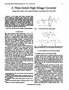
IV. RESULTS FOR 121 CELL ARCHITECTURE Previous studies devoted to HAP cellular architectures [23] have often assumed circularly symmetric beams, and we will here show how elliptic beams can yield better coverage. An architecture studied in some detail is a conventional hexagonal cell layout, where 121 cells of 6.3-km diameter serve a 60-km diameter coverage area [21]. Choosing a channel reuse number (cluster size) of four yields three groups of 30 cells and a further group of 31 cells. CIR patterns for the latter group are illustrated in Fig. 7, where sidelobes have been modeled as a flat floor at 40 dB. The HAP height is 20 km. In Fig. 7, a comparison of CIR coverage for circular beams and elliptic beams are shown as contour plots where spacing is 3 dB and the labels are for the “top” contours. In the former case, the azimuth angle subtended by each cell from the HAP has been chosen to derive the 3-dB beamwidth for the circular beam. In this case, the beam is wider than it needs to be in the elevation plane, because the elevation angle subtended by the cell at the HAP is smaller than the azimuth angle subtended (with the exception of the central cell since it lies directly beneath the HAP). The resulting CIR pattern shows considerable distortion of the cells, which tend to be pushed radially away from their intended location. In contrast, when optimized elliptic beams are adopted, the regions of high CIR are both better geographically defined and exhibit higher CIR. The geographical coverage for both cases is quantified in Fig. 8 as the fractional area of the cochannel cell group served at a given CIR threshold. The optimized elliptic beams offer a clear advantage in terms of CIR offered. The same trend is followed very closely for the other three cell groups in this reuse plan.
(b) Fig. 7. CIR contours for one channel of four. (a) Circular beams. (b) Optimized elliptic beams.
Fig. 8.
Coverage for channel 1 of four channels.
By further processing of the data arrays, the geographical relationships between the coverage areas of the four cell groups may be illustrated. Gaps in the coverage may be shown at a chosen CIR threshold and regions of overlap may also be studied. To illustrate these effects, Fig. 9 shows the coverage at a CIR threshold of 18 dB and also the geographical overlap
THORNTON et al.: OPTIMIZING AN ARRAY OF ANTENNAS FOR CELLULAR COVERAGE FROM A HIGH ALTITUDE PLATFORM
Fig. 10.
(a)
489
CIR channel overlap for combinations of four channels.
is served by at least two channels, 40% by at least 3, and 2% by all four channels. An intuitive conclusion is that the cell edges tend to receive multichannel coverage. This may be useful to boost the capacity at the cell edges, where the CIR and power budget due to the primary channel is weakest. It is also worth observing that coverage everywhere is at least 15 dB. This is consistent with Fig. 5, where the coverage on channel 1 becomes less than unity at about 15 dB. A. Coverage for Different Reuse Schemes
(b) Fig. 9. Examples of geographical coverage and overlap. (a) Coverage on all channels at 18 dB. (b) Overlap between channels 1, 2, and 3 at 10 dB.
between channels 1, 2, and 3 at a threshold of 10 dB. (The dark shaded regions are above the threshold CIR and the cells are labeled with their channel numbers.) While Fig. 9(a) shows an arbitrary 18 dB threshold level, the graphic shows the tendency for the CIR coverage (and, hence, quality-of-service) to be worse in the central region, while coverage exists beyond the intended 60 km diameter circle which is shown. The result is instructive in illustrating the difficulty of controlling the geographical coverage with a fixed reuse plan. Also, Fig. 9(b) shows, by way of example, the overlap regions for channels 1, 2, and 3. The dark areas receive coverage with a CIR of at least 10 dB by all three of these channels. To quantify such effects Fig. 10 shows the fractional coverage for various channel overlap combinations. In this case, the overlap is shown as the fraction of the total service area (of 60-km diameter) which is served at a given exceeded CIR threshold. For example, at a CIR of at least 10 dB, 80% of the coverage area
Having established a formulation for optimized antenna beamwidths, it is interesting to compare different reuse plans (or cluster sizes) and also the effect of sidelobe levels. For an increase in the channel reuse number, while the bandwidth allocated to each channel is linearly reduced, an improvement in CIR is expected due to the decrease in the number of interfering beams and also the reduced beam overlap. On increasing the number of channels to seven and retaining the optimized elliptic beams, Fig. 11 shows contour plots of the CIR for one of the channels, where there are 17 cells. This cellular pattern is repeated six times, while the seventh channel (which also includes the central cell) has a total of 19 cells. The contours spacing is again at 3 dB intervals, and two cases are shown for sidelobe levels at 40 and 50 dB. The geographical coverage for the two cases is shown in Fig. 12, which also shows results for the four channel scheme. For seven channels and sidelobes at 50 dB, the maximum CIR is increased by 10 dB as expected and the roll-off occurs at a higher CIR threshold. For the four channel case, the roll-off is less clearly improved on adopting 50-dB sidelobes because there is less angular separation between cells and the cell edges suffer interference from neighboring antenna main lobes. Therefore, on reducing the sidelobe power, the cell centers experience reduced interference but the cell edges retain interference from neighboring main lobes. When seven channels are used, the increased angular separation obviates main lobe overlap, and the predominant interference mechanism is from sidelobes. Therefore, on reducing sidelobe levels, the majority of the coverage area experiences reduced interference in the seven channel case. B. Channel Overlap Returning to CIR coverage using seven channels and sidelobes at 40 dB, the overlap between channels is presented in
490
IEEE TRANSACTIONS ON WIRELESS COMMUNICATIONS, VOL. 2, NO. 3, MAY 2003
Fig. 13. (a)
(b) Fig. 11. CIR contours for one of seven channels. (a) Sidelobes at (b) Sidelobes at 50 dB.
0
Fig. 12.
040 dB.
Effect of sidelobe level on coverage for one of nc channels.
Fig. 13, which shows the fractional simultaneous coverage by a number of channels. For example, there is 100% coverage by at least one channel up to a CIR of 19 dB, and by any two channels up to a CIR of 13 dB and so on. The trend that the coverage reduces for an increasing number of overlapping channels is an expected one.
Geographical channel overlap shown as multichannel coverage.
When traffic loads are uneven the overlap can be exploited to provide additional capacity when one cell is full, provided the received power is sufficiently high. The high degree of overlap is not usually seen in conventional terrestrial situations because it implies: • base station redundancy, as power falls off typically at distance ; • higher transmit power, which is required to serve longer link lengths; • more channels to complete the reuse plan, e.g., to achieve full overlap base stations can be arranged in multiple overlapping layers, each with its own conventional reuse plan. However, despite these disadvantages it is used in indoor systems where the propagation environment is harsh and base station redundancy is needed to maintain coverage [14]. In the case of the HAP architecture, the interference mechanism is different (power falls off less sharply at first, followed by a steeper roll-off beyond the edge of cell). A high degree of overlap is achieved without the need for additional channels and base station redundancy, with the added advantage that the link lengths do not change significantly. Finally, a comparison of the four and seven channel schemes is shown in Fig. 14 as plots of CIR and power for cross sections through the center of rows of cells. In both schemes, the antennas and, hence, power budgets are identical and both cases of CIR are shown. The power is scaled as the maximum antenna directivity as seen on the ground, minus the excess free space loss relative to the subplatform point. Thus, at the subplatform point—the center of the central cell row in Fig. 11(a)—the antenna directivity is 22 dB. An interesting result is that as the ground distance increases, the directivity of the elliptic beams increases more rapidly than the free space loss and, hence, the power budget improves slightly. The tendency for the CIR to improve at the edge of the coverage region compared with the center, which has been illustrated in Fig. 9(a), is again clearly shown. One mechanism contributing to this effect is that the antennas serving the outer cells are more directive. This leads to a near-constant power level compared with which the interference is less severe for the more distant cells due to the greater free space loss. Also, the most distant cells have fewer neighbors and, hence, experience less interference from neighboring main lobes.
THORNTON et al.: OPTIMIZING AN ARRAY OF ANTENNAS FOR CELLULAR COVERAGE FROM A HIGH ALTITUDE PLATFORM
Fig. 14.
491
CIR and power through cell rows. (a) Central row of cells. (b) Adjacent row to central row.
V. CONCLUSION A number of issues related to cellular planning for broadband services delivered from HAPs have been explored. A key factor is the shape of antenna beams and their effect on obtainable CIR patterns. While the work is not specific to any RF frequency, the emphasis is on bands between 28 GHz and 48 GHz and aperture antenna radiation patterns have been approximated using curve-fit methods. Elliptic beams have been shown to offer advantages in terms of optimized power at cell edges, which is of most importance where RF link budgets are marginal. By tailoring each antenna’s beamwidths to its corresponding cell’s subtended angles an array of antennas is suggested to serve a chosen coverage area. While the physical demonstration of these beams has not been presented, the form of the modeled beams is both realistic and tractable for the purposes of cellular service characterization which has been presented in detail. Conventional reuse patterns of four and seven channels, using hexagonal cells, have been studied. In each case, elliptic antenna beams which provide maximum power at cell edges have been utilized. Where four channels are used, cell edges suffer interference from neighboring beams and a reduction in sidelobe level produces a corresponding improvement in CIR at cell centers only. When seven channels are used, the benefit of reducing sidelobe levels is enjoyed across the majority of the coverage area. A significant amount of overlap between channels has been shown, which suggests a useful mechanism for adaptive resource allocation and handover between cells. REFERENCES [1] R. Steele, “Guest editorial—An update on personal communications,” IEEE Commun. Mag., pp. 30–31, Dec. 1992. [2] G. M. Djuknic, J. Freidenfelds, and Y. Okunev, “Establishing wireless communications services via high-altitude aeronautical platforms: A concept whose time has come?,” IEEE Commun. Mag., vol. 35, pp. 128–135, Sept. 1997. [3] B. El-Jabu and R. Steele, “Effect of positional instability of an aerial platform on its CDMA performance,” in Proc. IEEE Vehicular Technology Conf., vol. 5, Sept. 1999, pp. 2471–2475. [4] D. Grace, N. E. Daly, T. C. Tozer, and A. G. Burr, “LMDS from high altitude aeronautical platforms,” in Proc. IEEE GLOBECOM’99, Dec. 1999, pp. 2625–2629. [5] B. El-Jabu and R. Steele, “Aerial platforms: A promising means of 3G communications,” in Proc. IEEE Vehicular Technology Conf., May 1999, pp. 2104–2108.
[6] D. Grace, N. E. Daly, T. C. Tozer, A. G. Burr, and D. A. J. Pearce, “Providing multimedia communications from high altitude platforms,” Int. J. Satellite Commun., no. 19, pp. 559–580, Nov. 2001. [7] N. J. Colella, J. N. Martin, and I. F. Akyildiz, “The HALO network,” IEEE Commun. Mag., vol. 38, pp. 142–148, June 2000. [8] W. C. Y. Lee, “Spectrum efficiency in cellular,” IEEE Trans. Veh. Technol., vol. 38, pp. 69–75, May 1989. [9] D. Grace, T. C. Tozer, and A. G. Burr, “Reducing call dropping in distributed dynamic channel assignment algorithms by incorporating power control,” IEEE J. Select. Areas Commun., vol. 18, pp. 2417–2428, Nov. 2000. [10] M. M.-L. Cheng and J. C.-I. Chuang, “Performance evaluation of distributed measurement-based dynamic channel assignment in local wireless communications,” IEEE J. Select. Areas Commun., vol. 14, pp. 698–710, May 1996. [11] J. C.-I. Chuang, “Performance issues and algorithms for dynamic channel assignment,” IEEE J. Select. Areas Commun., vol. 11, pp. 955–963, Aug. 1993. [12] L. J. Cimini, G. J. Foschini, C.-H. I, and Z. Miljanic, “Call blocking performance of distributed algorithms for dynamic channel allocation in microcells,” IEEE Trans. Commun., vol. 42, pp. 2600–2607, Aug. 1994. [13] J. Zander, “Peformance of optimum transmitter power control in cellular radio systems,” IEEE Trans. Veh. Technol., vol. 41, pp. 57–62, Feb. 1992. [14] L. F. Chang, A. R. Noerpal, and A. Ranade, “Performance of Personal Access Communications System—Unlicensed B,” IEEE J. Select. Areas Commun., vol. 14, pp. 718–727, May 1996. [15] A. D. Olver , P. J. B. Clarricoats, A. A. Kishk, and L. Shaffai, Microwave Horns and Feeds: IEE Press, 1994, p. 266. [16] B. El-Jabu and R. Steele, “Cellular communications using aerial platforms,” IEEE Trans. Veh. Technol., vol. 50, pp. 686–700, May 2001. [17] C. A. Balanis, Antenna Theory, Analysis and Design, 2nd ed. New York: Wiley, 1997, pp. 812–813. [18] Instruments and Components Catalogue, U.K.: Flann Microwave Instruments Ltd., 1998. [19] C. A. Balanis, Antenna Theory, Analysis and Design, 2nd ed. New York: Wiley, 1997, pp. 48–49. [20] N. Adatia, B. K. Watson, and S. Ghosh, “Dual polarized elliptical beam antenna for satellite application,” in International Symposium Digest. Antennas and Propagation. Piscataway, NJ: IEEE Press, 1981, vol. 2, pp. 488–491. [21] J. Thornton, D. Grace, C. Spillard, T. Konefal, and T. Tozer, “Broadband communications from a high altitude platform—The European HeliNet programme,” IEE Electron. Commun. Eng. J., vol. 13, pp. 138–144, June 2001. [22] D. Grace, J. Thornton, T. Konefal, C. Spillard, and T. C. Tozer, “Broadband communications from high altitude platforms—The HeliNet solution,” in Proc. Wireless Personal Multimedia Communications, WPMC 2001, Aalborg, Denmark, Sept. 2001. [23] N. E. Daly, T. C. Tozer, D. Grace, and D. A. J. Pearce, “Frequency reuse from high altitude platforms,” in Proc. Wireless Personal Multimedia Communications (WPMC 2000), Bangkok, Nov. 2000.
492
IEEE TRANSACTIONS ON WIRELESS COMMUNICATIONS, VOL. 2, NO. 3, MAY 2003
John Thornton received the M.Sc. degree in microwave physics from the University of Portsmouth, Portsmouth, U.K., in 1995 and the Ph.D. degree in microwave engineering from Open University, U.K., in 2002. He has previously held research positions in the U.K. at the Rutherford Appleton Laboratory, developing submillimeter wave solid state sources for space applications, and thereafter in the Department of Engineering Science, University of Oxford, Oxford, U.K., working on a number of diverse communications projects which included passive radar transponders, adaptive antennas, and superconducting filters for broadcast and cellular applications. In 2000, he returned to the University of York to join the Department of Electronics and maintains research interests in antennas, self-phasing arrays, microwave techniques, and broadband applications.
David Grace (S’95–A’99–M’00) received the M.Eng. degree in electronic systems engineering in 1993 and the Ph.D. degree on “Distributed Dynamic Channel Assignment for the Wireless Environment”from the University of York, Helsington, York, U.K., in 1999. Since 1994, he has been a Member of the Communications Research Group, University of York, where he is now a Research Fellow. He has worked on a variety of research contracts including several from the Defense Evaluation and Research Agency. Current research interests include broadband communications from high altitude platforms, and dynamic channel assignment/multiple access schemes for multimedia communications. He is now Project Manager for the EU Framework V HeliNet Project at the University of York, being responsible for broadband communications.
Myles H. Capstick received the B.Sc. and Ph.D. degrees in electronics from the University of Wales, Bangor, U.K., in 1987 and 1991, respectively. He was appointed to the post of Lecturer in 1990 at the School of Electronic Engineering, University of Wales, and moved to the University of York, Helsington, York, U.K., in 1996. His research interests are centered in microwave and millimeter-wave circuits and systems, including optical generation and distribution of millimeter and microwaves, multigigabit optical communications and millimeter-wave and microwave filters, diplexers and planar antennas. He has been a partner in both the European RACE Project MODAL and ACTS Project FRANS responsible for planar antennas and filters for the fixed wireless access systems in these projects. Dr. Capstick is an Associate Member of the Institution of Electrical Engineers (IEE), U.K.
Tim C. Tozer (M’81) received the M.A. degree in computer engineering from the University of Cambridge, U.K. He is a Senior Lecturer in electronics at the University of York, Helsington, York, U.K., since 1987, and Leader of the Communications Research Group. His current interests include multiuser communications, spread-spectrum techniques, and satellite communications systems. He is the holder of several substantial grants and research contracts from industry and government organizations. He has served on the Government Advisory Committee of the U.K. on the use of the radio spectrum (3.4–30 GHz), and continues to have connections with the U.K. Radio Communications Agency through membership of Technical Working Parties on mobile and terrestrial propagation (TWP), and microwave, fixed link and satellite (MFLSC). He is Vice-Chair of IEE Professional Group E9 (Satellite Systems and Applications) and has been invited to present at the NORTEL Wireless Forums in Richardson, TX. (1997) and in Ottawa, ON, Canada (1998). He has previous experience in industry and was a Principal Scientific Officer at DERA (Malvern and Defford), engaged on military satellite systems. Dr. Tozer is a Fellow of the Institution of Electrical Engineers (IEE), U.K.