connect electrodes and the recorder) often constitute a source of noise to the ... the acquisition and wireless transmission of a signal from sensor to recorder. In.
The City College of New York The City University of New York (CUNY) Biomedical Engineering Senior Design I
Wireless ECG Monitoring System Project Report Coordinators: Prof. Marom Bikson Prof. Luis Cardoso Teaching Assistant: Gaurav Agarwal Sponsor: National Aeronautics and Space Administration Project Team Members: Mohamed Osman Ndongo Khouma Sadia Abbasi Atia Syed Mizanur Rahman Neranjan Da Silva
TABLE OF CONTENTS 1
INTRODUCTION .......................................................Error! Bookmark not defined.
2
PRIOR ART .............................................................................................................. 7 2.1 2.2 2.3 2.4 2.5 2.6 2.7 2.8
3
SPECIFICATIONS FOR WIRELESS BIOMONITOR SYSTEM ................... 13 3.1 3.2
4
The Lifeguard Crew Physiological Observation Device (CPOD) ....................... 7 UltraView Telemetry ........................................................................................... 8 The Myomonitor Wireless EMG System............................................................. 9 Crystal Monitor 20-B ........................................................................................... 9 Ambulatory Data Acquisition System ............................................................... 10 Biomedical Wireless and Ambulatory Telemetry for Crew Health (BioWatch)11 LifeSync Wireless ECG System ........................................................................ 11 Hospital bedside monitors.................................................................................. 12
Specifications for Wireless Electrode Module (Required and Desired) ............ 13 Specifications for the Receiver Unit (Required and Desired)............................ 16
DESIGN CONCEPTS ............................................................................................ 18 4.1 General Design Concept .....................................Error! Bookmark not defined. 4.2 Specific Concepts................................................Error! Bookmark not defined. 4.2.1 Concept 1 .....................................................Error! Bookmark not defined. 4.2.2 Concept 2:....................................................Error! Bookmark not defined. 4.2.3 Concept 3:....................................................Error! Bookmark not defined. 4.2.4 Wireless transmission options .....................Error! Bookmark not defined.
5
DESIGN SELECTION................................................Error! Bookmark not defined.
6
BUDGET…………………………………………………………………………..20
7
REFERENCES.............................................................Error! Bookmark not defined.
2
LIST OF ILLUSTRATIONS
FIGURES Figure 1- Representative Schematic of Normal ECG wavefom..................................................... 6 Figure 2- The Lifeguard Crew Physiological Observation Device (CPOD) and components [5]. 8 Figure 3- UltraView Telemetry [22]............................................................................................... 8 Figure 4- The Myomonitor wireless EMG module connected to the input module [7]. ............... 9 Figure 5- Patient unit and the wireless receiver connected to a PC [6]. ....................................... 10 Figure 6- The base recorder of ADAS [2]. ................................................................................... 11 Figure 7- Components of the Biomedical Wireless and Ambulatory Telemetry for Crew Health [2].......................................................................................................................................... 11 Figure 8- The patient transceiver (sensor unit) and monitor transceiver (receiver unit) of the LifeSync Wireless ECG System [11]. .................................................................................. 12 Figure 10- (a). Indicates the final prototype of the circuit, major active components include INA 126p, a microcontroller MSP430 (Taxes Instrument Inc., ), the Bluetooth® module, numeric LCD, D/A converter, serial port (RS232) and a 3.7V battery. (b). Indicates the final case design for the Wireless ECG system. Input includes three electrodes (negative, positive and ground) where as the outputs include RS232 and analog line out. A USB port allows battery recharging. The front panel also features on/off switches for the device and Bluetooth® as well as indicative LEDs for power and Bluetooth®. .................................... 22 Figure 14- Graphical User Interface for Wireless ECG Monitoring System................................ 28 Figure 15- Cost of Wireless ECG Monitoring System Vs Other Currently Marketed ECG Systems. ................................................................................................................................ 29 TABLES Table 1- Specifications of bedside monitors commonly used in hospitals................................... 13 Table 2- Specifications Table for Sensor Unit.............................................................................. 16 Table 4- Specifications Table for Sensor Unit.............................................................................. 18 Table 5- Comparative Cost Table For Commonly used ECG Monitoring Systems..................... 29
3
1
ABSTRACT
2
INTRODUCTION
The monitoring of vital physiological signals has proven to be one of the most efficient ways for continuous and remote tracking of the health status of patients. Electrocardiogram monitors are often used in many medical service centers and hospitals to diagnose and monitor a person’s health status by measuring their cardiac activity. An ECG is a noninvasive monitor, which can be utilized to evaluate the heart electrical activity, measure the rate and regularity of heartbeats, the position of the chambers, identify any damage to the heart and investigate the effect of drugs and devices used to regulate the heart. This procedure is very useful for monitoring people with (or susceptible to) impairments in their cardiac activity. In addition, during surgical procedures, the electroencephalogram (EEG) is measured along with his/her ECG to track the consciousness level of a patient during anesthesia [7]. Other physiological parameters such as oxygen saturation in hemoglobin, electromyography and blood pressure similarly provide vital information about the health of a given person when continuously monitored.
One of the invariable risks associated with space missions are the threats posed by the very harsh spatial environments to the physical and mental health of the astronauts. Being exposed to these types of environment for long periods of time has adverse impact on cardiac, muscular, and neurological functions on astronauts [3] (example of reduced gravity, high temperatures, planet dust particles, solar rays, etc). Fortunately, the continuous monitoring of physiological parameters such as electrocardiography, electromyography, electroencephalography, oxygen saturation in hemoglobin and variability of cardiac frequency may provide crucial information for a rapid diagnosis of medical conditions in astronauts; preventing the growth of any health condition to proportions susceptible to cause mission failure or even death of a crew member.
To provide a means to continuously monitor several physiological parameters using just one device, a variety of multi-parameter monitors (or biomonitor) systems have been introduced in the past few years, with many of them currently used by hospitals, researchers, and NASA. Although, these devices are commonly used to detect, process and record several physiological signals simultaneously, the conventional telemetry system they employ limits the freedom of movement of the subjects whose biopotentials are being measured. First of all, most of these systems receive power from an electrical outlet and are heavy enough to require wheeling to be displaced; making casual movements or urgent transportation of patients from one location to another very difficult [24], thus resulting in patients being mostly confined to their beds while in a hospital. Moreover, besides limiting the freedom of mobility of the subjects, the wires (used to connect electrodes and the recorder) often constitute a source of noise to the acquisition system.
4
And, although such stationary conditions might be acceptable in the case of a bed-ridden patient, it cannot be used for astronauts who are required to constantly move by their activities during space flights. The alternative commercially available biomonitoring devices which can be used under severe non-stationary conditions such as athletic scientific studies are very limited and prove to be costly. These devices are also usually uncomfortable due to their heavy weight, vigorous structure and network of lead cables running from subject to monitor.
The goal of our project is to design and fabricate a wireless biomonitor to help eliminate the restrictions caused by lead wires in conventional systems used in hospitals or by NASA by permitting the acquisition and wireless transmission of a signal from sensor to recorder. In hospitals, our device would readily be adaptable to any system used to monitor physiological parameters, notably bedside ECG monitors, wireless capable computers and portable ECG monitors, thus allowing a patient’s vital signs to be kept track of at all times despite his/her proximity to a bedside monitor. This device will also be designed to be used by NASA as an adaptor for their physiological monitoring systems that make use of telemetry to acquire biopotentials. This allows the continuous monitoring of the patient’s vital signs despite his/her proximity to a bedside monitor.
Together with its wireless capabilities, this biomonitor system will have to meet several design specifications including NASA’s technical standards for portable bioinstrumentation to ensure safety and functionality. Hence, this device will be battery powered, double insulated and isolated from the ground to keep it from constituting an electrical hazard to the astronaut or the spacecraft. The device susceptibility to electromagnetic interference will be minimized to produce more accurate signals. Audio and visual alarms will be also be implemented into the device (recorder/receiver unit) in order to warn the user when a measured parameter reaches a critical level. Furthermore the extruded plastic casing will also make this device robust enough to be worn during physical activities such as exercise or research tasks.
This project primarily pertains to the development of a wireless monitoring system for ECG. However, the techniques and design concepts used in the development of this system can be used for the development of a multi-parameter (ECG, EEG, EMG, oxygen saturation, etc) wireless biomonitor system.
3
BACKGROUND
Electrocardiography is a medical diagnostic procedure used to record the electrical activity of the heart and display it as a waveform. An electrocardiogram (ECG) is obtained by measuring
5
electrical potential between various points of the body using an instrumentation amplifier linked to the body via leads attached to electrodes (electrical contacts). Electrodes are placed on different sides of the heart to measure the activity of various parts of the heart muscle and the voltage between pairs of these electrodes is what is returned as ECG in the form of a graph. A typical ECG tracing of a normal heartbeat (or cardiac cycle) consists of a P wave, a QRS complex and a T wave (Figure 1). The baseline voltage of the electrocardiogram is known as the isoelectric line. Typically the isoelectric line is measured as the portion of the tracing following the T wave and preceding the next P wave. The waveform and the relationship between the different sections composing it can be used to determine heart rate as well as distinguish various cardiac arrhythmias including tachycardia (abnormally high cardiac rhythm >100 bpm, bradycardia (an abnormally slow cardiac rhythm < 60 bpm).
Figure 1- Representative Schematic of Normal ECG wavefom.
Currently, there are two different types of ECG systems that are used. The first one is the standard ECG which generally involves twelve or fifteen leads that are connected to the patient’s chest, arms and right legs through electrodes. The device records the ECG signal for almost thirty seconds [2]. Possible ailments can be discovered from reading the ECG signal. However, due to the short time for sampling, sporadic abnormalities which mostly occur in the intensive care unit (ICU) patients may not be discovered.
6
In order to address the problem mentioned above, continuous electrocardiogram telemetry is used by many hospitals to monitor patients in the ICU. This device has three electrodes that acquire ECG signal for an extended period and then the signal is displayed on a screen or printed on an ECG graph paper. The Wireless ECG Monitoring System proposed here falls in this second category of ECG devices as it will be used to monitor the cardiac activity of subjects. Many ECG machines, both standard and continuous, are marketed as “portable”, but are not necessarily small and lightweight. In addition, most such appliances receive power from an electrical outlet and are sufficiently heavy that they must be mounted on a cart and wheeled from one location to the next. Wireless devices have the potential to significantly improve this situation by reducing the weight and size of such devices and eliminating the need for power or lead cables. The purpose of this project is to design a working prototype of an ECG that acquires the electrocardiograph from astronauts or patients and sends it wirelessly via Bluetooth to a receiver unit such as computers and hospital monitors. This device will save time and effort for the nurses who are constantly following the patients’ conditions and help them to operate more efficiently. At the same time, the goal of this project is to minimize the cost of the device so hospitals can afford one for every patient, especially the ones that are in the ICU. In the next section, previous ECG devices are introduced, as well as their shortcomings.
3
PRIOR ART
3.1 THE LIFEGUARD CREW PHYSIOLOGICAL OBSERVATION DEVICE (CPOD) One of the biomonitors that is used for monitoring astronauts’ health is Crew Physiological Observation Device (CPOD) which is composed of 3 units (Fig.1). Unit 1 is “a small wearable computer” which is the central unit. This unit analyzes the physiological signals; acquired from unit 2 (the external sensors). Unit 2 is composed of an ECG, respiration, blood oxygenation (SpO2) and blood pressure sensor. All physiological signals are sent wirelessly using Bluetooth from unit1 to unit 3 (Tablet PC). Unit 3 is used to display the physiological signals and store them. Unit 3 doesn’t only serve as a receiver, but it also calculates heart rate and breath rate from the received signals. Another feature in unit 3 is that the received and calculated data can be stored on a removable media [5]. Despite the device can be connected to Accutracker II [5], its blood pressure sensor has high motion sensitivity. Because signals from the sensors are transmitted to the wearable computer via lead wires, the latter can easily constitute an obstacle during motion or can be accidentally disconnected at any time. Moreover, weak wire connections may cause artifacts or signal acquisition failure.
7
Figure 2- The Lifeguard Crew Physiological Observation Device (CPOD) and components [5].
3.2 ULTRAVIEW TELEMETRY The UltraView Telemetry unit (Fig. 2) monitors the physiological signals of heart and SpO2 through a multi-parameter patient worn transmitter. The signals are transmitted wirelessly and displayed on any Spacelab monitor [21]. One of the advantages of this device is that it allows the monitoring of more than one person at the same time. However, the UltraView Telemetry lacks other crucial sensors that are vital for monitoring astronauts’ health such as EEG and EMG. Moreover, the devices’ sensors also are connected to multi-parameter patient worn transmitter via wires which may obstruct its users from certain motions.
Figure 3- UltraView Telemetry [22].
8
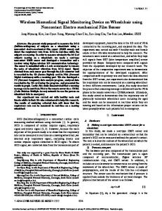
3.3 THE MYOMONITOR WIRELESS EMG SYSTEM This is another device used to specifically monitor muscle activity using a wireless EMG sensor. The device is composed of two units with the first one consisting of the wireless EMG sensor module (Fig. 3), which acquires the signals from the input module connected to the EMG electrodes via lead wires and transmits them to the second unit, the Myomonitor Datalogger. This second unit is used for the display and storage of measured data [6]. The Myomonitor detects EMG signals optimally at the skin surface, thus reducing the introduction of noise and artifacts in the EMG signals.
Figure 4- The Myomonitor wireless EMG module connected to the input module [7].
3.4 CRYSTAL MONITOR 20-B This device is designed primarily to monitor patients for any sleep disorder breathing (SDB). The patient unit is a small hand-held device worn or carried by the patient (Fig.4). This unit contains channels for up to ten sensing modules: EKG, EEG, chin and leg EMG, pulse Oxymeter, airflow, snore, thoracic and abdominal effort, and body position sensors. It transmits the data wirelessly to a receiver that displays and stores the data on a PC (Schmidt).
The patient unit does not have any external antenna, which decreases its size. An SD memory card is used to store patient’s data. It functions as a mediator between the receiver and the sensors, which adds more weight, devices and wires to the subject.
9
Figure 5- Patient unit and the wireless receiver connected to a PC [6]. . 3.4 AMBULATORY DATA ACQUISITION SYSTEM The Ambulatory Data Acquisition System (ADAS) is composed of the recorder base (Fig.5) and the signal input module. The recorder base acquires signals from twelve sensors through the signal input module. These twelve sensors are EKG, EEG, EMG, EOG, EGG, body position, limb position, heart rate, blood pressure, skin temperature, respiration and skin conductance level. After the sensors pick physiological signals, they are processed, displayed, saved and transmitted to a HRF portable computer (PC), which allow the users to setup the recorder base and view the signals [8].
The ADAS has a 32 bit processor. It has the ability to record signals with very small amplitudes (0-125 mV) and differentiated analog signals from -62.5mV to 62.5 mV (Delsys Inc., 2004). In order to have a continuous monitoring of the astronaut’s health, the astronaut has to wear the base recorder the whole time that weights approximately 1 Kg (Delsys Inc., 2004). Also, the base recorder will be connected to the electrodes via wires that may reduce the astronaut’s freedom of motion.
10
Figure 6- The base recorder of ADAS [2]. 3.5 BIOMEDICAL WIRELESS AND AMBULATORY TELEMETRY FOR CREW HEALTH Zin Medical’s Biomedical Wireless and Ambulatory telemetry for Crew Health (BioWatch) is a light weight (155 to 190g depending on number of channels in use) device used to monitor the health status of a subject. It can measure EKG, EMG, EEG, EOG, blood pressure, blood glucose, heart rate, joint angle, oxygen level in blood, temperature and acceleration. Data acquired by BioWatch is transmitted wirelessly to a PC [9]. The BioWatch also uses lead wires to connect electrodes thus the device has to be worn by the subject at all times during physiological monitoring.
Figure 7- Components of the Biomedical Wireless and Ambulatory Telemetry for Crew Health [2] 3.6 LIFESYNC WIRELESS ECG SYSTEM The LifeSync Wireless ECG System is an innovative method for monitoring a patients ECG without the attachment of any data cable between the electrodes and the monitor. This device (Fig.9) is composed of a patient transceiver, which acquires the biopotential via leads attached to 3 or 12 electrodes placed on the subject’s skin. This unit is usually worn on the arm. Once, the
11
signals are acquired, they are amplified and wirelessly transmitted using a Bluetooth module embedded in this first nit to a secondary unit, the monitor transceiver. The monitor transceiver is connected via input cables to a conventional monitor which then processes the signal as usual: numerical display of heart rate, graphical display of waveform, etc [12]. The two units together make up for a small very low weight system (i.e. patient transceiver has dimensions of 8 x 12.5 x 3 cm and weight of 240 g) that allows its users more freedom of movement without jeopardizing continuity of ECG monitoring. It also, eliminates the need for detaching and reattaching lead wires when a patient needs to be transported [11]. The absence of heavy obstructing cables also reduces the amount of noise that interferes with the signal displayed on the monitor as a waveform.
Figure 8- The patient transceiver (sensor unit) and monitor transceiver (receiver unit) of the LifeSync Wireless ECG System [11].
3.7 HOSPITAL BEDSIDE MONITORS In addition to these biomonitors used for acquisition and processing of several different physiological parameters, there exist a variety of other monitors most often used in hospitals to monitor the health status of patients. One of the distinct features of these monitors is their usually bulky sizes, making them bedside appliances rather than portable ones as they are sometimes marketed to be. These monitors offer a range of different options for parameters measured and their specifications. Table 1 below presents a sample of bedside monitors used to measure different physiological parameters. The specifications must be thoroughly considered and constitute one of the basis for the minimum required specifications for the system proposed here.
12
Measured Parameter (s)
Display Type
Display Size
Frequency Response Range
AT-33 Single Channel EMG
EMG
Numerical LED, Light Bar
0.5 inch high
25 – 425 Hz
LifePAK 10
ECG, Heart Rate, Temperature and BP
Numerical & Graphical
7.25 x 4.35 cm2
0.05 – 100 Hz
GE Marquette® Eagle 3000
ECG, Temperature, SpO2
Graphical
Criticare® Scholar EL
Heart Rate, ECG,BP, Impedance Respiration, Temperature, SpO2
Active Color LCD
121 x 91 mm
ECG
Graphical
7.6 x 5.7 cm2
0 – 150 Hz
6.4 inches high
0.5 – 40 Hz
Biomonitor Model
Schiller Cardiovit AT101 3-Channel ECG MiniMax 4000
ECG,BP,ETCO2,Temp, Numerical & SpO2 Graphical
9 inches diagonally
0.05 – 100 Hz
0.05 - 100 Hz
Table 1- Specifications of bedside monitors commonly used in hospitals.
4
SPECIFICATIONS FOR WIRELESS BIOMONITOR SYSTEM
4.1 SPECIFICATIONS FOR WIRELESS ELECTRODE MODULE (REQUIRED AND DESIRED) The primary objective of this design project is to build a device capable of eliminating the need for lead wires to monitor the cardiac activity of a subject using standard bedside electrocardiographs such as General Electric’s Marquette® Eagle 3000 or portable biomonitors such as NASA’s Ambulatory Data Acquisition System [2]. This means that the system will be required to have specifications that can encompass such ECG monitoring systems.
13
The integrity of the signal while it is wirelessly transmitted to the receiver or relayed to an electrocardiograph via input cables is a very important aspect of this system. It is important that a physician or astronaut using continuous ECG monitoring be able to objectively notice variations in a subject health status based on the trends of the waveform of the signal. Moreover, a distorted signal can cause erroneous medical diagnostic or inaccuracy of measured values (e.g. heart rate). For this reason, the wireless biomonitoring system must have a signal to noise ratio (SNR) deemed acceptable for ECG signals and possibly for other types of signals. Since the voltage amplitude of non-amplified ECG can be approximated to 5mV [12], we require that the maximum amplitude of any noise present in the filtered signal to be 5 μV or less (gain is not incorporated here). Hence, the required SNR for the sensor node is given as:
SNR = 20*log (Asignal/ Anoise) = 65 dB SNR = 20*log (5000 μV / 5 μV) = 60 dB
Equation 1
In order to optimize the performance of the signal acquisition system, the desired SNR will be set at 100 dB. This will allow our system to also accommodate the needs of other biopotentials as far as the strength of the desired signals compared to the undesired ones.
The dimensions and weight requirements of our proposed system should demonstrate added value on the dimensions and weight of the LifeSync Wireless ECG System. As such, our sensor node is required to weight less than 240 g and have length, width and thickness such that the devices dimensions are < 8 x 12.5 x 3 cm. We will strive to render this unit as small as possible (weight of < 100 g and dimensions < 5 x 10 x 2 cm are desired goals).
Other required and desired design specifications include requirements for power supply, battery life for continuous operation of the wireless electrode module (input unit), operating temperature, current discharge rate, maximum allowable leakage current (As specified by NASA standards for portable biomonitors), etc. The design requirements for these specifications are listed in Table 2.
14
Parameter
Required
Desired
Remarks
Measured Parameters
ECG
EMG, EEG
Most common biopotentials measured by biomonitors
100 dB
The voltage amplitude of ECG signal is approximately 5mV; the max. amplitude of any noise present in the filtered signal is required to be ≤5 μV (before gain). Sensor and receiver units are not expected to be distant (>10m) from one another in a hospital setup. When patient is mobile portable receiver will serve as continuous monitoring system for biopotentials.
Signal to noise Ratio
60 dB
Wireless Transmission Range
10 m
100 m
Battery Life (continuous)
≥ 8 Hrs
≥ 12 Hrs
Long battery life will reduce need to interrupt patient monitoring
< 100 g
This unit is required to be lighter than the Patient Transceiver unit of the LifeSync Wireless ECG System.
< 8 x 12.5 x 3 cm
< 5 x 10 x 2 cm
This unit is required to have dimensions less than the patient transceiver unit of the LifeSync Wireless ECG System.
Power Supply
Battery with less than 30V capacity
Rechargeable Battery with less than 5V capacity
NASA technical standards requires the use of batteries with potential less than 30 V DC for bioinstrumentations (NASA STD 3000, Vol I Section 6.4.3.13)
Max. Leakage Current
0.070 mA
≤ 0.070 mA
Values as required by NASA technical standards (NASA STD 3000, Vol. I)
-20 to 75º C
Range must include both expected room temperature and skin temperature. Also takes into account burn hazard (NASA STD 3000, Vol. I))
None Specified
Depends on wireless transmission method used (e.g. Bluetooth = 2.4 GHz)
Weight Dimensions (antenna, wires & electrodes not included)
Operating Temperature
Wireless Transmission Freq.
< 240 g
20 to 42º C
15
Bandwidth
Length of Electrode Wires
None Specified