1 Nov 2006 - an essential capability for military, public safety, and ... cooperative geolocation solution to provide location ... Security and Public Safety.
WIRELESS SENSOR NETWORK WITH GEOLOCATION James Silverstrim and Roderick Passmore Innovative Wireless Technologies Forest, VA 24551 Dr. Kaveh Pahlavan Worcester Polytechnic Institute Worchester, MA 01609 Dr. Brian Sadler US Army Advanced Research Laboratory Adelphi, MD 20783
ABSTRACT Geolocation for indoor and urban areas is becoming an essential capability for military, public safety, and commercial wireless applications. These systems are crucial for situational awareness, enabling soldiers and first responders to complete their missions in a more secure, controlled environment that can save lives. Maintaining situational/positional awareness in indoor and urban environments is difficult because buildings, walls and other obstacles obstruct vision and RF propagation. Innovative Wireless Technologies (IWT) and Dr. Kaveh Pahlavan of Worcester Polytechnic Institute (WPI) partnered to develop an innovative cooperative geolocation solution to provide location accuracy of better than 1 meter for outdoor to indoor conditions. This solution is a variation of the WiMedia group multi-band orthogonal frequency division multiplexing (MB-OFDM) ultra wideband (UWB) waveform standard that has been developed for the commercial market. The UWB waveform developed by IWT provides extended range capability of over 250 meters at data rate of 300 kbps.
1. INTRODUCTION Maintaining situational/positional awareness in indoor and urban environments is difficult because buildings, walls and other obstacles obstruct vision and RF propagation. Propagation channels are typically characterized by direct line of sight (DLOS) and non-line of sight (NLOS) performance. As more obstruction is added to the propagation channel, the DLOS path amplitude decreases relative to the NLOS path due to multipath and shadow fading. Thus, the DLOS path, which is the key enabling parameter for geolocation, is harder to detect. The challenge is to develop geolocation algorithms that overcome the DLOS obstructions and
integrate the algorithms into a communication network that is easily deployed, low cost, and provides accurate and reliable location information.
2. REQUIREMENTS The geolocation requirements include light-weight, low-power, small-size portable devices that can be rapidly deployed in an ad-hoc network. Each node will provide high resolution, near real-time geolocation for situational awareness in urban/indoor operations. The devices must provide robust data communication for exchange of information and operate in the presence of undesired interference. The military devices must also provide low probability of detection/interception by the enemy.
3. PROJECT OBJECTIVES The key project objectives provided by the Army Advanced Research Lab were as follows • Establish scientific foundation for evaluation of indoor and urban geolocation systems • Develop innovative algorithms for UWB geolocation • Define suitable architecture for real-time implementation • Develop working prototype radios and demonstrate real-time experiment • Provide user with robust real-time method to determine accurate position estimation • Develop solutions for DoD, Homeland Security and Public Safety There is not a sufficient scientific foundation for understanding the behavior and analyzing the performance of location based sensing systems. A key task of the geolocation project is to collect path data to establish an empirical model specific to detection of the
Form Approved OMB No. 0704-0188
Report Documentation Page
Public reporting burden for the collection of information is estimated to average 1 hour per response, including the time for reviewing instructions, searching existing data sources, gathering and maintaining the data needed, and completing and reviewing the collection of information. Send comments regarding this burden estimate or any other aspect of this collection of information, including suggestions for reducing this burden, to Washington Headquarters Services, Directorate for Information Operations and Reports, 1215 Jefferson Davis Highway, Suite 1204, Arlington VA 22202-4302. Respondents should be aware that notwithstanding any other provision of law, no person shall be subject to a penalty for failing to comply with a collection of information if it does not display a currently valid OMB control number.
1. REPORT DATE
2. REPORT TYPE
01 NOV 2006
N/A
3. DATES COVERED
-
4. TITLE AND SUBTITLE
5a. CONTRACT NUMBER
Wireless Sensor Network With Geolocation
5b. GRANT NUMBER 5c. PROGRAM ELEMENT NUMBER
6. AUTHOR(S)
5d. PROJECT NUMBER 5e. TASK NUMBER 5f. WORK UNIT NUMBER
7. PERFORMING ORGANIZATION NAME(S) AND ADDRESS(ES)
8. PERFORMING ORGANIZATION REPORT NUMBER
Innovative Wireless Technologies Forest, VA 24551 9. SPONSORING/MONITORING AGENCY NAME(S) AND ADDRESS(ES)
10. SPONSOR/MONITOR’S ACRONYM(S) 11. SPONSOR/MONITOR’S REPORT NUMBER(S)
12. DISTRIBUTION/AVAILABILITY STATEMENT
Approved for public release, distribution unlimited 13. SUPPLEMENTARY NOTES
See also ADM002075., The original document contains color images. 14. ABSTRACT 15. SUBJECT TERMS 16. SECURITY CLASSIFICATION OF: a. REPORT
b. ABSTRACT
c. THIS PAGE
unclassified
unclassified
unclassified
17. LIMITATION OF ABSTRACT
18. NUMBER OF PAGES
UU
6
19a. NAME OF RESPONSIBLE PERSON
Standard Form 298 (Rev. 8-98) Prescribed by ANSI Std Z39-18
DLOS path for indoor-to-indoor and outdoor-to-indoor environments. This model is used to develop and optimize signal processing algorithms and a system architecture that provides real-time geolocation capability.
direct path followed by multipath signals. The offset between the green line and the first peak is a measurement delay which is removed.
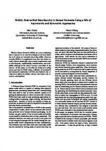
4. TECHNICAL APPROACH The geolocation design approach uses an ultra wideband waveform that IWT developed based on the WiMedia group MB-OFDM standard. The 528MHz bandwidth waveform provides 200 bits per symbol to achieve very high data rates at short range. IWT has added an algorithm variation to extend range to achieve ranges of greater than 250 meters and provide range versus data rate flexibility from 200 Mbps @ 10 meters to 300 kilobits/second @ 250 meters. The MB-OFDM PHY has been adapted to an IEEE 802.15.4 based MAC to provide ad-hoc mesh networking capability. The waveform is designed for high multi-path, indoor environments and supports tailoring of the RF spectrum to mitigate RF interference and coexistence issues. 4.1 Data Collection The key to developing a geolocation waveform is to define a realistic path model. IWT and WPI defined a data collection system to measure the impulse response of the propagation channel over a RF spectrum of 3-6 GHz using a network analyzer as shown in Figure 1.
Figure 2: Typical Channel Impulse Response Using the s-parameter data we can perform signal bandwidth tradeoffs. Figure 3 shows a comparison of the time domain waveform for bandwidths of 3GHz, 500MHz and 10MHz.
Figure 1: Data Collection System The s-parameters obtained from the network analyzer can be applied to multiple bandwidths using the Agilent ADS and MATLAB to compare various processing algorithms. IWT and WPI have collected hundreds of measurements for indoor-to-indoor and outdoor-to-indoor scenarios for multiple building constructions to develop empirical path models. These models are especially appropriate for analyzing the performance of geolocation algorithms based on time-ofarrival (TOA). A typical channel impulse response is provided in Figure 2. The green line shows the expected delay of the direct path based on measured physical distance between the transmit antenna and the receive antenna. The red lines are the delays corresponding to the first peak signal and the maximum signal. In this case, the first peak is the
Figure 3: Waveform Bandwidth Effect Both the 3GHz and 500MHz bandwidths allow separation of the direct path from multipath signals. However, the 10MHz bandwidth provides no separation which prevents a good TOA measurement. The TOA measurement is based on Two-Way Time Transfer (TWTT) which is well suited for ad-hoc mesh deployment since there is no infrastructure and precise synchronization to a common clock is not required. The message transmission requirements and timing equations are shown in Figure 4.
Figure 4: TOA Calculation The TWTT calculation is also useful for network time-synchronization, frequency-offset error measurement and error correction. Based on the data collection two distance-power relationships have been developed for geolocation as shown in Figures 5 and 6. The first is a one piece line based on a continuous path from transmitter to receiver. The second is a two piece line based on discontinuous path from transmitter to receiver where the breakpoint in the curve occurs at the distance of the first obstruction.
Figure 6: Power-Distance – 2nd Scenario 4.2 Signal Processing Algorithms The geolocation network concept is an ad hoc mesh that includes three types of nodes: Mobile Nodes, Gateway Nodes and Reference Nodes. • Mobile Nodes are carried or worn by soldiers and first responders. They are small, lightweight and battery operated and can interface with biometric sensors as well as other equipment such as Future Force Warrior multi-function display/touchpad.
Figure 5: Power-Distance – 1st Scenario A summary of the UWB channel characteristics from the data collection of indoor-to-indoor and outdoor-toindoor conditions includes the following. • DLOS has high path loss with power exponent of 6 to 10 typical at distances > 10m • A dense multi-path impulse response of up to several hundred nanoseconds is typical • There can be up to 100 nanoseconds between DLOS path and strongest path (more for outdoors) • Typical power difference between DLOS path and strongest path is 26dB with up to 40dB observed.
•
Gateway Nodes perform inter-network routing and incorporate an interface to link the mesh network to a wide area command and control network (e.g. Soldier Radio Waveform).
•
Reference Nodes are used to orient, anchor and/or extend the range of the network. These nodes are packaged for ease of deployment, are battery operated, and include a GPS receiver to provide a network reference. Strategic placement of Reference Nodes is important to good geolocation performance. In the event that GPS is not available, the system provides relative location of each unit in the network.
The processing functions required for each geolocation node is shown in Figure 7. Time measurement and the ranging algorithm involve high speed processing of the ranging waveform while ranging refinement, positioning and user interface are associated with a general purpose processor.
Figure 7: Geolocation Signal Processing The geolocation waveform is similar to the MBOFDM sync header which is processed using a matched filter and integrator based on the IWT extended range algorithm as shown in Figure 8. Further processing is required by the ranging algorithm to measure time delay and signal strength of the DLOS signal and peak signal. This information is passed to the ranging refinement function and positioning filter.
through selective sub-carrier removal and multi-band hopping. A number of positioning algorithms were evaluated including non-cooperative algorithms and cooperative algorithms. The non-cooperative algorithms included Least Square, Weighted Least Square, Residual Weighted Least Square and Davidon. The cooperative algorithms included Savarese and a novel algorithm developed by WPI called Cooperative Localization with Optimum Quality of Estimate (CLOQ). A typical scenario is shown in Figure 9 with four references nodes and a number of mobile nodes. In all scenarios the cooperative algorithms provided better overall performance due to the exchange of positioning information between nodes. The CLOQ algorithm provided the best performance because it includes a quality of estimate (QoE) parameter based on the relative signal strength of each RF link.
Figure 9: Typical Positioning Scenario The CLOQ positioning sequence is as follows. On the first iteration after startup the reference node broadcast and the mobile nodes listen. Mobile nodes with an adequate number of references calculate their location and QoE. Each node with estimates of their location then broadcast their location and QoE. Nodes with best QoE establish themselves as anchors. On the next iteration, the newly elected anchors plus original anchors are used for selection of another set of anchors. The positioning algorithm repeats until all nodes become anchors and estimate their QoE. Based on WPI simulations, the average position error varied from 1.5 meters for 5 mobile nodes to < 0.5 meter for 40 nodes. Figure 8: Extended Range Processing The signal processing provides rapid sync acquisition of