JOURNAL OF COMMUNICATIONS, VOL. 2, NO. 4, JUNE 2007
65
Wireless Stand-alone Portable Patient Monitoring and Logging System1 Taha Landolsi and A. R. Al-Ali American University of Sharjah/Computer Engineering Department, Sharjah, UAE Email:
[email protected];
[email protected]
Yousef Al-Assaf American University of Sharjah/Electrical Engineering Department, Sharjah, UAE
[email protected] Abstract—In this paper, we propose a wireless stand-alone, embedded system design that integrates the monitoring of three biomedical parameters into a single personal medical device. The three parameters are: blood glucose level, heart rate, and pulse oximetry. The goal of this work is to build a compact and cost-effective device capable of monitoring several medical parameters while patients conduct their normal daily activities, and store these parameter readings in an embedded system-based portable device. A communication protocol and patient monitoring software application are developed to store data that can be later downloaded to a physician’s workstation for analysis and diagnosis. Index Terms— Wireless Embedded Systems, Patient Monitoring Systems, e-Healthcare, Healthcare informatics.
I. INTRODUCTION In today’s healthcare practice, physicians have a need to monitor more than one medical parameter for patients that are either hospitalized or leading their normal daily activities at home or at work but in need of constant medical care. These patients, in turn, need a device that is easy to use, cost-effective, and reliable to provide them with vital data about their medical condition. Such device should allow physicians to view the measured parameters over a long period of time for parameter/daily activities correlation and trend analysis. Many patient remote monitoring devices were reported in the literature [1-9]. An otolaryngology procedure was reported in [1]. The unit helps physician to perform a variety of procedures such as nasal endoscopy, biopsies and removal of foreign bodies. The developed protocol is implemented and tested to monitor the medical condition of a large number of patients [2]. The protocol receives the temperature and pressure of a patient using a mobile device that is attached to the patient’s body via short messaging system (SMS) message. The mobile device does not have data logging capabilities, nor does it have download and diagnosis features. The clinical usefulness
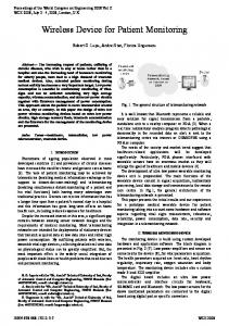
of a wireless personal digital assistant (PDA) based on a GPRS-capable cellular phone and an Internet application for remote monitoring of real-time vital signs was discussed in [3]. A wireless PDA-based physiological monitoring system for patient transport that uses wireless local area network (WLAN) technology to transmit patient’s biosignals in real-time to a remote central management unit was presented in [4]. Most of the above systems do not have logging capabilities to allow the patients to be away for a week or so without communicating with their physician. Instead, biomedical signals are transmitted in real-time to the physician in these solutions. This paper discusses the design of wireless mobile logging device using an embedded system platform. The unit is used to measure a patient’s blood glucose concentration in units of milligrams per deciliter (mg/dL), heart rate in beats per minute (bpm), and pulse oximetry in percentage of concentrated blood oxygen (% Sp02). The architecture of the patient monitoring systems is shown in Figure 1. While the patient practicing his/her normal day activities, the acquired signals values are logged for a period of time or until the next physician visit. The platform stores a set of x number of values for each signal. The data of a trial period of one week is downloaded to a PC using the RS-232 port and analyzed using a custom-built software application. Rapid prototyping options and ease of firmware upgrade are crucial for such a device. For these reasons a C program was developed and customized for low-power consumption and reduced measurement time. The system architecture is given in section II, whereas section III shows the embedded-system hardware design methodology. A prototype for the system was successfully built and tested as explained in section IV.
1 Based on “Portable Integrated Multi-Signal Patient Monitoring System ", by M. El Korek, R. Aloul, T. Landolsi, A.R. Al-Ali, and Y. Al-Assaf which appeared in the 3rd International Conference on Innovations in Information Technology (IIT06). © [2006] IEEE.
© 2007 ACADEMY PUBLISHER
66
JOURNAL OF COMMUNICATIONS, VOL. 2, NO. 4, JUNE 2007
MultiMon Patient Monitoring Device
Biosensors Heart pulse rate Oxygen level Glucose level
E-Med Application
Single-Chip Microcontroller
RS-232
Data download Trend analysis
Physician PC
Figure 1 Architecture of the patient monitoring system.
II. SYSTEM ARCHITECTURE AND REQUIREMENTS The integrated monitoring system called MultiMon (Multi-signal Monitor) is responsible for converting the biophysical readings into numerical values that are stored in the microcontroller’s EEPROM memory. A. System Architecture The sources of these biophysical readings are two biosensors that are interfaced to the embedded system. The first one is the blood glucose sensor. A chemical reaction inside the sensor takes place upon contact with the blood sample and the glucose concentration of the blood sample applied by the patient is converted by the sensor into a voltage appearing at the output terminal of a quadruple, low-power operational amplifier [5]. This voltage is interfaced to the MultiMon system through the embedded system’s 10-bit analog-to-digital converter. MultiMon system with interfaces to biosensors
Blood glucose sensor
Heart rate & pulse oximetry biosensor
Figure 2. MultiMon prototype (side view)
The second biosensor is the heart rate and pulse oximetry sensor which is composed of a finger unit and a micro integrated circuit [6]. A patient inserts his/her index finger into the unit (See Figure 2). Two infrared and visible red light signals are transmitted through the finger and received inside the finger unit with the magnitude of the received signal indicating the patient’s blood oxygen concentration and heart rate. The integrated circuit is responsible for transmitting this information through a specialized transmitter line at CMOS voltage levels in serial format. The transmitter line is interfaced to a serial communication interface at the MultiMon system. In the typical mode of operation, the patient uses the MultiMon device for an extended period of time, typically for several weeks before returning it to the supervising physician who can download the stored data
© 2007 ACADEMY PUBLISHER
to a local PC through the RS-232 port. The E-Med software application is designed to display the medical parameter readings in a variety of graphical formats. The application also stores individual records for different patients in order for physicians to analyze and diagnose a variety of cases. B. Requirements After a requirements elicitation phase which involved medical physicians as the major stakeholders, the following set of requirements has been specified in order for the device to meet a minimum set of specifications provided by these stakeholders. In its functionality, the device should have the ability to collect medical parameter measurements of blood glucose, heart rate and blood oxygen level. Each of the biosensors responsible for measuring these medical parameters must be directly interfaced to the device’s embedded system-based platform. Adding to this, the device must have the ability to store the measured medical parameter values for a predefined period of time (called the trial period). These values must be transferable through a standard networking interface from the device to a computing device. In order for these values to be displayed by physicians for patient diagnosis purposes, a software application that is compatible with the device must be developed. Developers and system engineers must have the ability to upgrade the device’s firmware as needed or upon request of enhanced functionality from the stakeholders. The performance of the device is also of major importance for its users. It must have the ability to render a blood glucose reading in a period that does not exceed 1 minute from the time of blood sample application. It should also have the ability to render a heart rate reading and a blood oxygen level reading in a period that does not exceed 30 seconds from the time a patient switches on the heart rate and pulse oximetry sensor while the latter’s index finger is inserted. Another set of functional requirements has been specified for the E-Med software application. The application must have the ability to poll the stored medical parameters readings by establishing a communication link with the MultiMon device. It should also have the ability to read an identification code unique to each device. This ID is used to differentiate between the different patients’ devices when several patients are monitored during the same period of time. After reading this information, the application must have the ability to store the medical parameter readings into a patient-information database. The attributes for each patient record are the patient’s name, age, deficiency, and a unique ID that serves as the public key. The date at which the device has been given to the patient must be also stored by the application. Finally, the supervising physician must have the ability to use a variety of plotting options as shown in Figure 3.
JOURNAL OF COMMUNICATIONS, VOL. 2, NO. 4, JUNE 2007
67
Given these criteria, the Minidragon+ embeddedsystem board was chosen. The core area of the board does not exceed 6×8 cm in size. Its embedded system, Freescale™ MC9S12DP256B™ microcontroller unit (MCU), is a 16-bit RISC platform with several on-chip peripherals and modules [7]. The Minidragon+ has 12 KB of SRAM and 256 KB of flash memory. As shown in Figure 4, several modules were used in order to establish the following interfaces:
Figure 3. E-Med patient case analysis form, plotting all 3 parameters.
III. EMBEDDED-SYSTEM DEVICE DESIGN This section looks at the design of the embedded system-based device. Several considerations are taken into account. First, an embedded system-based platform was needed with enough memory to hold the medical parameter readings over an extended period of time. Second, the device must be accurate to make precise conversions from the voltage readings to meaningful biophysical values. Third, the device must have the networking options needed to transfer the data into a computing device as mentioned earlier.
Figure 4 Heart rate and pulse oximetry sensor interface with Minidragon+™ platform.
B. Heart Rate and Pulse Oximetry Biosensor Interface A communication protocol was devised to enable the MultiMon device to transfer the data to the E-Med software application. After connecting the device to the serial port of the physician’s PC, the latter must run the application and select the appropriate serial port number. As soon as the port is selected, the physician has to press an upload button on the device. The device then sends its 3-character device ID encoded between 42 values for each of the medical parameters.
Blood Glucose Test Blood Glucose Concentration (mg/dL)
160 140 120 100 80 60 40 20 0 1
2
3
4
5
6
7
Time of the Day MultiMon© readings
Glucomen™ readings
Figure 5 Comparison between blood glucose readings of the MultiMon device and Glucomen®.
© 2007 ACADEMY PUBLISHER
A Blood Glucose Biosensor Interface The biosensor’s output voltages are produced by a quadruple operational amplifier. One terminal has a typical voltage level of 2.98V as stated in [5]. However, different voltage values were produced at this terminal according to the glucose concentration of the blood sample residing at the patient’s test strip. This terminal is called the blood glucose voltage terminal. A second terminal produces a constant voltage value that is close to 500 mV every time a test strip is inserted. This terminal is called the strip-in terminal. After deducing these characteristics from a series of lab tests, each of the two terminals was connected to a channel from the 16 available channels of the Analog-toDigital (A/D) conversion module of the MCU. The device was programmed such that the sampling of analog data from the blood glucose voltage terminal starts after a device operation button is pressed by the user. The user must only press this button after the strip is inserted and the blood sample is identified by the blood glucose sensor through a short beep. This beep means that the sensor is ON. The 8-bit programmable A/D module converts the voltage values appearing at the blood glucose voltage terminal into a series of hex values. As shown in Figure 6, this conversion happens after 23 seconds to allow time for the blood glucose sample to react with the test strip and produced the desired voltage values. Three of these values are converted to integers, averaged, and incremented by an offset value to produce the final blood glucose concentration value in units of mg/dL.
IV. SYSTEM TESTING The patient monitoring system has been tested at two levels before a final system test was made. The heart rate and pulse oximetry measurement function was tested to completion in order to make sure that the unwanted serial data was dropped and meaningful values for heart rate and blood oxygen levels were displayed. Integrity tests
68
JOURNAL OF COMMUNICATIONS, VOL. 2, NO. 4, JUNE 2007
were then made on the displayed medical parameter values to make sure they were realistic. Figure 5 illustrates how the blood glucose measurement function was tested by comparing blood glucose values generated from the MultiMon device with the values produced by Glucomen™; a commercial blood glucose monitor. Seven tests were performed at a single day. The discomfort associated with invasive blood glucose testing twice for the same time period, and the lack of testing solution dictated this limited test. Nevertheless, 5 out of the 7 data points converged with two outlying points. Finally, the full device test was made several times with a variety of specimen. The results were verified using the ICC12 environment.
worked by the authors and its testing is under progress. The end-to-end monitoring system architecture is shown in Figure 7. This feature will enable the physician to communicate with several monitored patients via the public GSM mobile network. The physician can send an SMS command to the device, and the device can then respond by sending a SMS message that contains the latest reading.
GSM Network GPRS Modem
Biosensors Inputs
Strip inserted? Yes
Detect blood sample on strip
Time > 1 min? No
Strip detected; patient presses Operation button after BEEP
Print mg/dL reading on terminal and store In MultiMon©
sample A/D 23 sec.
Decode A/D conversion results
End
Figure 6 Blood glucose measurement algorithm using MultiMon.
The E-Med software application was first tested using an arbitrary set of medical parameter values. The communication protocol was tested later and verified with the device connected to the serial port of a PC. The uploaded medical parameter values were displayed on EMed using the software’s different display options. The current design relies on the RS-232 serial wireline connection to upload data from the device to the physician’s PC. This has several drawbacks. Perhaps the most important ones are that only one patient’s device can be communicated with at any given time, and the assumption that the patient(s) are capable of coming to the physician’s office on their own. The latter is a false one if the patient falls critically ill while being monitored. Adding a wireless communication interface between the monitoring device and the physician’s monitoring software is a desired additional feature that enhances the system communication capability. This feature is being © 2007 ACADEMY PUBLISHER
Database Server
Instructions to Patients
Figure 7 End-to-end architecture of the wireless patient monitoring system.
Initialize A/D, I/O, Sensors
Yes
GPRS Modem
MultiMon
Start
No
Physician’s Office
Monitored Patients
A communication protocol is devised for this purpose. As shown in Figure 8, the monitoring device MultiMon takes patient readings and stores them to the device EEPROM. Normal readings are periodically reported to physician’s monitoring system in the form of an SMS via the general packet radio service (GPRS) modem. The GPRS modem is interfaced with the MultiMon via the standard RS-232 serial port. These reading values are encapsulated in the appropriate data protocol unit (PDU) and transmitted by the modem over the air interface. Transfer data rates depend on the channel encoding used. A coding scheme called coding scheme 4 (CS-4) is used when the modem is near the GSM Base Transceiver Substation (BTS) while a coding scheme called coding scheme 1 (CS-1) is used when the modem is distant from the BTS. Using the CS-4 it is possible to achieve a data transfer rate of 20 kbit/s for a given time slot. GSM technology uses Time Division Multiple Access (TDMA) with 8 time slots per frame hence supporting 8 simultaneous users at any given time [10]-[12]. On the other hand, using CS-1 can only achieve a data transfer rate of 8 kbit/s per time slot. In either case, the transfer speed is more than adequate for the current application since the invasive blood glucometer cannot be more than a handful of reading a day, and the heart rate and pulse oximetry are only reported intermittently as explained in section III. In abnormal situations, the communication protocol is such that MultiMon reports unusual readings, such that excessive heart rates, hypoglycemic or hyperglycemic conditions, correlated with time of the day. A persistence time is allotted before reporting an alert SMS message to the physician’s monitoring system. This persistence time is necessary to avoid any unnecessary reaction to a sporadic reading that is not representative of the actual patient health condition. The E-Med software analyzes the reported data and correlates it to the patient’s known illness, the previously reported data, and the time of the day the abnormal readings were reported, and may choose to instruct the patient, or alternatively the care-giver, again through an SMS
JOURNAL OF COMMUNICATIONS, VOL. 2, NO. 4, JUNE 2007
message to take the necessary actions that can be lifesaving before healthcare professionals intervene. This novel design allows monitoring several patients at the same time, unlike the wireline solution presented in earlier sections. The monitoring and data reporting take place nearly real-time. This relieves incapable patients from needing to go in-person to the physician’s office. It also gives the healthcare professionals the ability to react promptly to life-threatening situations, in a proactive way that involves the patients themselves. Physician Monitoring System
MultiMon at Patient’s Home
Normal Readings
Params. Readin
gs SMS Msg. . . .
Abnormal Readings Persistence Time
Params. Readings
SMS Msg.
Alert SMS Msg.
SMS Msg. Instruction
Condition Analysis Time
Figure 8 Communication protocol designed to handle abnormal readings in monitored patients.
V. CONCLUSIONS A proof-of-concept for an embedded system-based, multi-signal patient monitoring system oriented for the out-patient consumer market has been established. The patient monitoring device has been developed using an embedded system platform and a collection of biosensors and discrete electronics. Three medical parameters have been selected as part of an application that targets patients suffering from specific deficiencies such as diabetes and cardiovascular diseases. These parameters are blood glucose concentration, heart rate, and blood oxygen level. A custom software application has been built to aid physicians in monitoring and diagnosing their patients’ cases. The device’s design and the software application provide major advantages over existing medical monitoring systems in the device’s prototyping surface area and the overall system’s development time which did not exceed 6 months. This functionality is provided with a cost-effective design due to the use of an allpurpose RISC-based microcontroller as opposed to a proprietary hardware platform. The overall system has been tested with the help of volunteers and the monitored medical parameter readings have been checked against results from existing commercial products. A design process for personal medical devices [8] has been adopted in addition to a software development process for the development of an integrated solution that aims to serve out-patients, physicians, and OEMs of medical equipment. The proposed design will soon be further enhanced with a wireless communication capability using the public GSM network.
© 2007 ACADEMY PUBLISHER
69
ACKNOWLEDGMENT The authors wish to acknowledge Mr. Mohammed ElKorek, Ms. Rawan Aloul, Dr. Ahmed Aloul (Khalifa Hospital, Ajman, UAE), Dr. Ahmed Sultan (Faculty of Medicine, University of Sharjah, Sharjah, UAE), and Dr. Srdjan Denic (Faculty of Health and Medical Sciences, United Arab Emirates University, Al-Ain, UAE) for their valuable contribution to this work. REFERENCES [1] F. Sigari, J. Schneider and J. M. Pinto, " Use of a mobile operative unit for in-patient otolaryngology procedures" Otolaryngology - Head and Neck Surgery, Volume 136, Issue 1, January 2007, Pages 125127 [2] A.R. Al-Ali, M. Al-Rousan and T. Ozkul, " Implementation of experimental communication protocol for health monitoring of patients" , Computer Standards & Interfaces, Volume 28, Issue 5, June 2006, Pages 523530 [3] P. Klootwijk, S. P. Nelwan, T. B. Van Dam and S. H. Meij, " Wireless (GPRS-Based) mobile real-time patient monitoring", Journal of the American College of Cardiology, Volume 41, Issue 6, Supplement 2, 19 March 2003, Page 528. [4] Y. Lin, I-C. Jan, Ko, P.C.-I., Y. Yu Chen, J.-M. Wong and G.-W Jan; " A wireless PDA-based physiological monitoring system for patient transport", Information Technology in Biomedicine, IEEE Transactions on Volume 8, Issue 4, Dec. 2004 Page(s):439 – 447 [5] Texas Instruments, TLV2254I Advanced LinCMOS™ Rail-to-Rail Very Low-Power Operational Amplifiers, February 1997 revised March 2001. [6] Smiths Medical, Inc., 31392B Micro power PCB Technical Description, November 2005. [7] Barrett and D. Pack, Embedded Systems Design and Applications with the 68HC12 and HCS12. New Jersey: Prentice Hall, 2005. [8] Smiths Medical, Inc., 31392B Micro power PCB Technical Description, November 2005. [9] M. El Korek, R. Aloul, T. Landolsi, A.R. Al-Ali, and Y. Al-Assaf, “Portable Integrated Multi-Signal Patient Monitoring System,” Proceedings of the IEEE conference on Innovation in IT, Dubai, 2006. [10] S. M. Redl, et al., "An Introduction to GSM", Artech House, March 1995. [11] M. Mouly, and M.B. Pautet, "The GSM System for Mobile Communications", 1992.
70
[12] GSM standards available on: http://www.3gpp.org.
A. R. Al-Ali received his Ph.D. from Vanderbilt University, USA, in 1990. Currently, he is a Professor of Computer Engineering at the American University of Sharjah, UAE. His research and teaching interests include: Embedded systems, microprocessors and microcontrollers, microcomputers, data acquisition units and PLC hardware and software architectures, remote monitoring and control using Internet, GSM, and GPRS networks. Taha Landolsi received his Ph.D. from the University of Texas at Dallas, USA, in 1999. He worked in the telecommunication industry for more than seven years designing and planning wireless and optical networks. He is currently an Assistant Professor of Computer Engineering, at
© 2007 ACADEMY PUBLISHER
JOURNAL OF COMMUNICATIONS, VOL. 2, NO. 4, JUNE 2007
the American University of Sharjah, UAE. His research interests include: wireless and optical networks, optical switching and computing, wavelet transforms applications to communications and signal processing, and MEMS applications. Yousef Al-Assaf received the B.S. degree in electrical engineering from Sussex University, Sussex, U.K., in 1984. He received the D.Phil. degree in control engineering from Oxford University, Oxford, U.K., in 1988. From 1991 to 1997, he worked with the Industrial Engineering Department, the University of Jordan, where he became Department Chair and Director of the College of Engineering Outreach Program. Since 1998, he has been with American University of Sharjah, Sharjah, United Arab Emirates, and currently he is the Dean of the School of Engineering and Professor of Electrical Engineering. His research interests include adaptive and predictive control, brain computer interface, and soft computing techniques.