1
Wirelessly-Charged UHF Tags for Sensor Data Collection Daniel J. Yeager, Student Member, IEEE, Pauline S. Powledge, Richa Prasad, Student Member, IEEE, David Wetherall, and Joshua R. Smith, Member, IEEE
Abstract— We present the WISP Passive Data Logger (PDL), an RFID sensor data logging platform that relies on a new, wirelessly-charged power model. A PDL has no battery yet (unlike a passive sensor tag) is able to collect data while away from an RFID reader. A PDL senses and logs data using energy stored in a capacitor; the capacitor can be wirelessly recharged (unlike active tags), and data can be uploaded whenever the PDL is near a reader. Standard EPC Generation 2 readers are used for WISP-PDL charging, ID-reading, and sensor data transfer. This allows WISP-PDLs to operate using commercial RFID readers as the only support infrastructure (for both data and power), and allows WISP-PDLs to co-exist with standard RFID tags. We describe the design and implementation of a prototype WISP-PDL, and report results from a short demonstration study that shows it can monitor the temperature and fullness of a milk carton as it is used over the course of a day. Index Terms—Data Logger, Passive RFID, Wireless Sensor
R
I. INTRODUCTION
tags equipped with sensors are being developed because of their potential to add value over identifieronly tags in a variety of settings. For example, perishable goods could be monitored while they are in transit to check that they are not subject to unsafe temperatures, and fragile goods could be monitored to detect unsafe accelerations that may cause breakage. Other applications include the detection of harmful agents and non-invasive biomedical monitoring. To date, sensor-enhanced tags fall into two broad categories based on conventional models for powering RFID tags. There are several examples of application-specific, long-range (UHF) passive tags with integrated temperature and light sensors, as well as an Analog to Digital Converter (ADC) FID
Manuscript received December 31, 2007. This work was funded by Intel Research Seattle. D. J. Yeager was an intern at Intel Research Seattle and is with the University of Washington, Department of Electrical Engineering, Campus Box 352500, Seattle, WA 98195-2500 USA. (e-mail:
[email protected]). R. Prassad is with the University of Washington, Department of Computer Science and Engineering (e-mail:
[email protected]). David Wetherall is with Intel Research Seattle and the University of Washington, Dept. of Computer Science and Engineering. (e-mail:
[email protected]) J. R. Smith, and P. S. Powledge are with Intel Research Seattle, 1100 NE 45th Street, 6th Floor, Seattle, WA 98105 USA (e-mail: {joshua.r.smith, pauline.s.powledge}@intel.com)
[1,2,3]. The benefits of passive tags are that they are inexpensive, disposable and can potentially last for tens of years if not longer. Consequently they can be embedded in objects for structural, medical, or product monitoring. The key limitation of these sensor-enhanced passive tags is that their operation requires proximity to an RFID reader. This greatly limits their use for capturing data through supply chains or other applications in which there is only partial reader coverage. In contrast, active, battery-powered tags with data logging capabilities have the advantage that they can be used when tags are not in proximity to an RFID reader because they carry their own power source. From a hardware standpoint, active tags range in complexity from battery-assisted passive tags that communicate with RFID readers at the low end to wireless sensor nodes at the high end. High end wireless sensor nodes can employ a reprogrammable microcontroller, large flash memory, numerous sensors, and wireless communication over Wifi, Bluetooth, Zigbee or custom protocols [4,5]. Unfortunately, the inclusion of batteries leads to several limitations. The first is finite lifespan, which ranges from 1 to 5 years in the aforementioned examples. Rechargeable batteries (which also have lifespan limits) require a charging infrastructure, usually a wired connection to a power source, and also incur the overhead costs of connecting the battery to the charger. Second, many batteries deteriorate or become hazardous at extreme temperatures. Third, batteries add cost, both directly through purchase cost and indirectly through the cost of regulatory disposal procedures. Lastly, the inclusion of battery chemicals such as lithium may be prohibitive for safety reasons. In this paper, we present a new, wirelessly-charged power model for sensor-enabled RFID tags in the form of a passive data logger (PDL) tag. PDLs aim to combine the best features of passive (battery-free) and active (battery-powered) tags. Like passive tags, PDLs use only the energy that they acquire from wireless signals to perform tasks. Like active tags, PDLs continue to operate when away from an RFID reader. To do so, PDLs store energy harvested from RFID reader signals in a capacitor, and later operate using this energy. For a similar physical size, the amount of energy PDLs can store is likely to be less than a semi-active tag. However, many settings include occasional reader contacts, e.g., supply chains feature relatively short intervals of data logging between
2 manufacturers, distributors, and retail stores. Thus, there are typically many opportunities for tags to wirelessly recharge at the various locations where passive tags are normally interrogated. This allows PDLs to be used repeatedly and to sustain their operation across occasional reader contacts despite their lack of an internal, long-lived power source. To demonstrate the feasibility of wireless-charging, we have built a prototype PDL, called the WISP-PDL, and used it for a small data collection study that we report later in this paper. Our prototype builds upon and extends our prior work on WISP (Wireless Identification and Sensing Platform) [1]. WISP is a fully-passive UHF RFID tag that uses an ultra-low power, 16-bit, general-purpose microcontroller for sensing, computation and RFID communication. The WISP-PDL inherits all the WISP’s design requirements, but adds an additional one: it needs to operate without proximity to an RFID reader. The WISP-PDL described in this paper is a new generation of WISP, presented here for the first time, that implements the EPC Class 1 Generation 2 communication protocol. Our prototype effort caused us to consider the problem of how to retrieve logged sensor from PDL tags. Earlier sensorenabled WISPs shoehorned sensor data into the low-order bits of Gen 1 EPC IDs; the tag emulated different IDs as it was queried for data. However, this strategy did not extend well to retrieving stored sensor data. Instead, our solution for the PDL presented here is to upload sensor data using the EPC Gen 2 protocol’s “tag memory” functionality. This has the advantages of compatibility with standard RFID tags via EPCcompliant tag IDs, and it allows us to perform data collection from PDLs as an application running on top of commercial RFID readers. The rest of this paper is organized as follows. After describing related work (Section II) we discuss the main design considerations in adding Passive Data Logging capabilities to WISP (Section III). We then present the hardware and software architecture of the WISP-PDL (Sections IV and V). We report on a short use study in which the WISP-PDL monitors the temperature of a milk carton over the course of a day (Section VI). Finally, we discuss other applications (Section VII) and conclude (Section VIII). II. BACKGROUND AND RELATED WORK Typical UHF RFID systems are designed to increase the visibility of goods in supply chains. A uniquely-numbered tag is attached to an item of interest, which is then wirelessly scanned at checkpoints in the supply chain. RFID readers wirelessly power and communicate with the tags at distances up to 10 m. Standard commercial tags have also been used for detecting parameters other than location. In our prior work, mercury tilt switches were used to toggle between two commercial tag ICs, allowing one bit measurement of object orientation [6]. Others have made a humidity sensor for detecting moisture in walls of buildings and houses by placing a sponge in front of a
tag [7]. Moisture in the sponge detunes the tag’s antenna, allowing approximation of humidity level from the read range of the tag. Finally, a custom tag for sensing high temperatures in food products used a fuse that melts above a particular threshold to enable or disable the tag [8]. These passive tags based on physical properties (e.g., a fuse that melts above a particular temperature) can “sense” while away from a reader but most are extremely limited in what they can report and are not reusable. PDLs aim to provide general and reusable sensing when away from a reader. Efforts have been made to retrieve richer, multi-bit sensor data from RFID tags for a wide variety of applications. Possible examples include infrastructure and object monitoring, automatic product tamper detection, identification of harmful agents, and biomedical devices for noninvasive monitoring [9]. To enable these applications, two regimes appeared: active battery-powered and passive battery-free tags. Most active tags are essentially wireless sensor nodes [4,5], as noted previously, though from a software standpoint they are mainly designed to communicate directly with a basestation, rather than peer-to-peer like many wireless sensor nodes. An active tag with adaptive analog sensor thresholds for triggering sensor measurements was proposed in [10]. By using a “quasi-active” state where analog circuitry wakes a microcontroller when sensors exceed defined thresholds, it can achieve better accuracy in capturing events than devices that routinely poll sensors on a time interval. Another class of battery-powered data-loggers used in supply chains is semiactive tags. They are battery-assisted rather than batteryoperated, using backscatter modulation for communication rather than a radio. [15] illustrates the use of 2.4 GHz semiactive tags in cold chain food monitoring for the army. However, semi-active tags generally suffer the same disadvantages as active tags due to their dependence on a battery. Many passive sensor-enhanced RFID tags tend to be application specific. A commercially-available, low-frequency RFID tag for detecting dangerous temperatures in food products during transit is reported in [9], although its range is too small for use in many applications. Other examples of application-specific, long-range (UHF) passive tags with integrated temperature and light sensors, as well as an Analog to Digital Converter (ADC) are [2,3]. We previously developed a general-purpose tag called WISP [1], which is a fully programmable passively-powered UHF RFID sensor tag. While these devices provide the benefits of passive, batteryfree operation, none can collect sensor data without proximity to an RFID reader. III. DESIGN CONSIDERATIONS The design constraints and challenges of passive sensorenhanced UHF tags have been thoroughly discussed in our prior work [1]. Additionally, there are a number of considerations we encountered while developing a PDL from
3
Average Current Budget (nA)
100000
1 Hour 1 Day 1 Week 1 Month WISP-PDL
10000 1000 100 10 1 1
10
100
1000
10000
100000
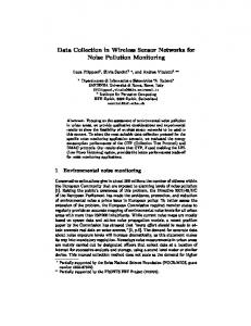
Capacitance (uF) Fig. 1. Average current budget for various runtimes and storage capacitors. ΔV = 3 V is assumed. Our WISP-PDL is marked with a circle.
our work on WISP. In general, these fall under three categories: run time, charge time, and RFID compatibility. A. Run Time The primary design consideration for a PDL is the sensor measurement and logging run time from a single capacitor charge. This run time is determined by the storage capacitor size and the time-averaged current consumption, Iave, during both sleep and active periods. As the maximum capacitor size is often fixed by size or cost, the maximum run time is then determined by Iave. We designed for a 1 day run time using a 0.1 F capacitor. A significant amount of effort was made reducing Iave to achieve the desired run time. Fig. 1 plots the approximate maximum Iave for various run times and capacitor sizes using the relationship I = C
Δv . Δt
This relationship allows accurate computation of the runtime if the current consumption is constant over voltage, and this is a reasonable approximation when the quiescent current is larger than the average active current. When the active current dominates and is drawn from a regulator, the amount of current drawn from the capacitor by the regulator is a function of the voltage on the capacitor. For applications with short-duration (100 µs to 10 ms) sensing / data logging and long sampling interval (1 second or more between samples), the quiescent current can potentially determine the minimum achievable Iav. A brief example illustrates this point. Assume a sensor measurement and flash memory write occur every 10 seconds and each event consumes 500 μA for 1 ms. The average current consumption of this workload (sensing and logging) is only 56 nA. However, the quiescent current of discrete component designs (not IC), can require several microamps (as shown in our design). The current consumption of the WISP-PDL, built with commercial off-the-shelf (COTS) components, is roughly equal to that of the previous example. Excluding parasitic
leakages, the quiescent current budget includes a 1 μA ultralow-power linear regulator, a 0.5 μA interval wakeup timer and a 0.3 μA voltage supervisor. This corresponds to a sleep current consumption of 1.8 μA. The active current is approximately 500 μA for 1 ms, but the sample time can be adjusted between hundreds of milliseconds to tens of seconds. As the quiescent current is the dominant consumer, a considerable improvement could be made using an external wakeup circuit to power on the remaining circuitry at regular intervals. For example, real-time clocks from Seiko [11] and Swatch [12] allow operation from an unregulated power source at quiescent currents of approximately 350 nA. This RTC could be used to enable the remaining circuitry. Although the reduced current consumption of a RTC represents some improvement over the regulated design, it was not enough to justify the added design complexity since we had met our run time design goal. There is a point of diminishing returns in optimizing both the active or sleep currents. When either current consumption is less than 10% of the other, little run-time is gained from further reduction of the smaller current consumption. Also, some capacitors have internal leakage resistances in the megaohm range, which also causes an upper bound on maximum runtime. For example, ceramic capacitors have lownanoamp to sub-nanoamp leakages. Electrolytic and tantalum capacitors can have hundreds of nanoamps of leakage. Double layer capacitors, which we employed for our design, have widely varying leakages from low-nanoamps to lowmicroamps. B. Charge Time A second consideration is the wireless charge time, with acceptable charge times depending on the intended PDL application. In general, it is important to characterize how fast the PDL can charge at any particular distance. Conservation of energy requires that the energy consumed during runtime first be charged into the storage capacitor, which is illustrated in equation 1. E stored =
(
)
1 2 2 C Vch arg ed − Vdd = Pch arg eTch arg e 2
(1)
The usable energy, Estored, is stored in voltage above the minimum operating voltage, Vdd. Energy stored in the capacitor at voltages below the PDL’s minimum operating voltage, Vdd, cannot be used. Thus the capacitor voltage must first charge up to Vdd after which surplus (i.e. usable) energy begins to accumulate. Due to component ratings, a maximum voltage, Vcharged, is enforced via overvoltage protection. The charge time is somewhat longer than the recharge time, because the charge time includes voltage from 0 V to Vdd as well as Vdd to Vcharged, while recharges only charge from Vdd to Vcharged. Equation 1 allows prediction of the charge time if the power supplied by the harvester, Pcharge, is known. Friis’ transmission equation allows prediction of the RF power available to the
4 35.000
Time (hours)
30.000 Recharge Time
25.000
Charge Time
20.000 15.000 10.000 5.000 0.000 0.00
2.00
4.00
6.00
8.00
10.00
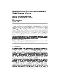
Meters Fig. 2. Charge and recharge time for 24 hours runtime with 1.8 uA average current. A 58 mF capacitor is required. In this example, the difference between charge- and re-charge times is negligible.
PDL over distance, and empirical RF to DC rectifier efficiencies can then be used to estimate Pcharge as a function of distance. Equation 2 is the logarithmic form of the Friis equation for path loss, with terms for polarization loss and rectifier efficiency included. ⎛ 4π d ⎞ Pch arg e = PT − 20 log ⎜ ⎟ + GT + GR − LP + 10 log10 (η ) ⎝ λ ⎠
(2)
The transmit power of the reader PT = 1 W = 30 dBm. Its center frequency is 915 MHz, corresponding to wavelength λ = 0.33 m. The transmit antenna gain GT = 6 dBi (this yields an effective isotropic radiated power of 4 WEIRP, the United States regulatory limit for this ISM band). The receive antenna gain GR = 2 dBi (the standard gain figure for a dipole antenna), and the polarization loss LP = 3dB. Loss LP occurs because only half of the power transmitted from the circularlypolarized transmit antenna is received by the linearlypolarized receive dipole antenna. Lastly, η = 30% is the rectifier efficiency, and this is approximated from empirical data using the WISP. (Since η is a fraction between 0 and 1, its logarithm is negative, which is why it is added on the right hand side.) Fig. 2 shows the predicted charge time versus range for the previously discussed efficiency, antenna gains, transmit power and stored energy based on Friis’ equation, assuming rectified power can be converted to Vcharged at a particular distance. WISP becomes voltage limited at 4.5 m; however, integrated circuit designs are able to achieve high conversion efficiencies up to 10 m [9]. Thus even at long distances from the reader, a PDL can charge overnight or over the course of a day, which is not unreasonable for many applications. Finally, an integrated circuit design can potentially achieve much lower power consumption and consequently much faster charge time for the same runtime as our discrete implementation.
C. RFID Compatibility Many supply chains have existing RFID infrastructure for use with standard commercial tags. Creating secondary wireless networks for sensing in supply chains is generally impractical, so it is desirable for PDLs to integrate into the existing RFID network. WISPs already harvest energy from standard reader signals. In addition, we needed to communicate sensor data using only standard commands. Fortunately, the EPC Class 1, Generation 2 specification provides a suitable interface for this task in the form of arbitrary, i.e., user-defined memory. This memory can be read and written with standard commands. We log sensor data into this memory and upload it by having the RFID reader perform a series of reads. We can also use this memory scheme to signal associated metadata such as whether there is more data to upload. This approach allows WISP-PDLs to operate on existing RFID networks without interfering with standard IDonly tags. Adding EPC Gen 2 support required a significant change in our software-defined protocol from previous versions of WISP as well as some modification to WISP’s hardware demodulation circuitry. IV. HARDWARE ARCHITECTURE The WISP-PDL is a new generation of WISP hardware with modifications for long run time data logging, EPC Gen 2 communication, and fluid level sensing. Previous WISPs were fully-passive, sensor-enhanced EPC Gen 1 RFID tags. In the WISP-PDL as well as prior WISPs, communication, sensing and computation are software defined in a general-purpose, reprogrammable Texas Instruments MSP430 microcontroller. WISPs include circuitry for RF power harvesting, modulation, demodulation, and voltage regulation that enable operation as a passive RFID tag. A detailed design discussion of WISP is found in [1], and therefore the bulk of this section will focus on areas specific to WSP-PDL. First, a high level description of the WISP-PDL is presented. Second, WISP-PDL-specific components are described in detail. Finally, a capacitive sensor is described. A. High Level Description The WISP-PDL’s high-level implementation is similar to previous WISPs, and a block diagram of the WISP-PDL is shown in Fig. 3. The analog front end contains a power harvester block that rectifies incoming RF energy into DC
Modulation Demodulation
Ant
Matching Network and Power Harvester
Power Management
Storage Cap Voltage Sense
Fig. 3. Block diagram of WISP-PDL.
Internal Flash Memory MSP430 Microcontroller Internal Temperature Sensor
External EEPROM
External Sensors
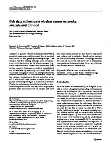
5 voltage to charge the storage capacitor. The power management block stores energy and provides regulated voltage for the system. The demodulator thresholds the enveloped RF carrier wave and converts the downlink (reader to tag) logic level to the regulated logic level. The modulation circuitry converts the uplink (tag to reader) waveform into a modulated tag reflection coefficient to the antenna. Lastly, a MSP430 microcontroller facilitates communication and sensor measurement. There are a few significant hardware changes in the PDLWISP from the previous WISPs. First, the demodulator was revised to enable Gen 2 communication. Second, the power management block was revised to reduce leakage and thereby lengthen run time. Third, an external EEPROM allows lowvoltage non-volatile data storage. Fourth, a capacitive sensor was added to enable various sensing applications. Lastly, a newer microcontroller (MSP430F2012) was used which allows 6 MHz operation at 1.8 V (versus 4 MHz at 1.8 V with the MSP430F1232) for nearly the same power consumption. This was needed in order to perform the more complex Gen 2 communication protocol. B. Demodulation and Power Management The demodulation and power management circuitry is shown in Fig. 4. Gen 2 reader-to-tag physical layer modulation (PR-ASK) causes smaller amplitude modulation deviations than Gen 1 ASK modulation. This required a new demodulator, which is similar to those used in silicon tag designs. Two low threshold DC schottky diodes are used to rectify the enveloped signal from the harvester. The current consumption of the comparator is used as a constant-current source, and the voltage across D7 detects current (high amplitude RF modulation) supplied by the harvester as a positive voltage, and lack of current (low amplitude RF modulation) as negative voltage. The comparator is used to generate a rail-to-rail logic level waveform, and the level shifter converts the unregulated logic level to the regulated logic level. It is important to optimize current consumption and speed when choosing a comparator; the Gen 2 protocol
requires roughly 1 µs propagation time, and minimal power consumption is desirable for maximizing the wireless range of the device. Storage capacitor C1 accumulates energy, which is rectified by D6. Over-voltage protection (OVP) clamps high rectified voltages to 5.5 V, and a low dropout, ultra-low-power linear regulator is used to provide 1.8 V regulated power for the system. Fig. 3 shows external sensors and EEPROM attached. External sensors are described shortly. An 8 Kbyte, 1.8 V EEPROM is used for logging data. Alternatively, the internal flash memory of the microcontroller may be used for logging small amounts of data; however, this necessitates a slightly higher regulated voltage of 2.2 V. Regardless of implementation, the EEPROM or flash memory will hence be referred to generally as non-volatile memory (NVM). C. Sensors A number of sensors can be integrated into the WISP-PDL, including those previously implemented on WISP (rectified voltage, light level, temperature, and orientation). Other interesting sensors that we have not yet integrated but have been explored for active and semi-active tags include humidity, vibration, sound, bearing (via digital compass) and others [10]. We implemented a capacitive sensor for fluid level sensing in our demonstration study. Capacitive sensing is a popular method for sensing user input in devices such as the Apple iPod, human presence in automatic airbag enable/disable in automobiles, distance in digital calipers, and displacement in MEMS accelerometers, as well as directly sensing gas pressure, liquid level, and other parameters. It is also the case that capacitive sensing can be accomplished with minimal components and low power consumption. In its simplest incarnation, measurement of the discharge time of an RC circuit can be used to estimate capacitance. More advanced designs provide enhanced noise immunity, directivity of sensing and accuracy [13]. We achieved reasonable accuracy with a simple RC discharge measurement. A configurable microcontroller port I/O pin is used for sensing. The pin is first set as an output to charge the sense capacitor to Vdd. Next, the pin is set as an input (output tri-state buffer set to high-z) and the
Cups of Water
0 1 2 3 4 5
Fig. 4. Power management (bottom) and demodulator (top)
TABLE I CAPACITIVE SENSOR CALIBRATION RESULTS Capacitance Fill Expected Fill Absolute Error (pF) (%) (%) (%)
15.6 16.1 16.6 17 17.6 18
1 21 42 61 82 98
0 20 40 60 80 100
1 1 2 1 2 2
Water was poured into a rectangular milk carton in fixed-volume (“cup”) increments. The RC discharge time was measured and converted to capacitance and also to fill percentage using (3). The capacitance is then compared against the expected linear increase in fluid level.
6 microcontroller’s timer is used to measure the discharge time from Vdd to the input buffer threshold of approximately Vdd / 2. In some microcontrollers, the pin input leakage could be used as the parallel resistor, but the MSP430 has such low leakage that a 10 MΩ resistor is necessary to create a discharge rate in the hundreds of microseconds range.
C measured − C Min C Max − C Min
% Fill = 100
(3)
We characterized the sensor to understand the relationship between fluid level and capacitance. Table I shows experimental data versus linear steps for fill percentage. Fill percentage was calculated using (3). Note that the measurement was taken inside the physical range of the sensor (the bottom of the sense wires to the top of the sense wires in Fig. 6). V. SOFTWARE ALGORITHMS The microcontroller firmware implements EPC Gen 2 communication, periodic sensor sampling and data logging. Generally, the microcontroller spends most of its time in a low power sleep mode. An internal timer wakes the microcontroller periodically to take sensor measurements and potentially log the measurement. When the WISP-PDL is queried by an RFID reader and there is new logged data, the four communication states on the right side of Fig. 5 are executed. Note that portions of the Gen 2 specification not used for retrieving the ID or sensor data are not yet implemented. There are two primary challenges in the design of the software. The first is maximizing time spent in the microcontroller’s low-power sleep states. This minimizes the
Query Sensors
Send RN
Δ < Vt
Sleep Mode (LPM 3+VLO)
Send ID
Timeout
DT W O t VL up err Int
Compare sensor data against last logged data =Δ
RF I Qu D On ery +
Ack
Request RN
Send RN
Δ Vt
Re ad
>
Write to EEPROM/Flash and Enable RFID
Send Data Read
Fig. 5. Software state diagram. The center state is the low power sleep state. A very low frequency oscillator (VLO) triggers interrupts every 4 seconds (VLO WDT Interrupt), which measures the sensors and potentially stores data to NVM. The right side of the diagram shows the EPC Gen 2 communication cycle, which culminates in Read queries extracting logged sensor data from NVM.
active current consumption. Second, general purpose microcontrollers are not designed to efficiently perform RFID communication because they process software instructions while custom silicon RFID tag state machines process many instructions in parallel. Custom, optimized communication algorithms are necessary to achieve RFID data rates with a 6 MHz clock speed and also to keep power consumption at a minimum. Fig. 5 shows a state diagram of the WISP-PDL data logging and communication cycles. The center box represents the sleep state, and a low-frequency, low-power oscillator is used to periodically wake the device from this sleep. These timer interrupts trigger the data logging cycle, shown on the left side of Fig. 5. First, sensors are powered on and sampled using the microcontroller’s 10-bit ADC. To conserve NVM and power, not all sensor measurements are stored. Current sensor measurements are compared against the last stored sensor measurements, and if the difference Δ exceeds a threshold Vt, the new sample is logged to NVM. Also, each sample is time stamped using a count of the number of timer interrupts. Finally, when a new sample is logged to NVM, the RFID interface is enabled so that the new data may be retrieved by a nearby reader. The implemented portion of the EPC Gen 2 communication cycle is illustrated on the right half of Fig. 5. If the RFID interface is enabled, a Query command from the reader begins the communication session. Several further commands precede the Read command, which allows the reader to download logged data from NVM. A fully erased NVM Read data packet is used to mark the end of valid NVM data. The reader then issues an additional read command past the end marker, which signals the WISP-PDL to disable its RFID interface. This last step is required because Gen 2 protocol does not provide an acknowledgement to the tag that the read command was successful, and the tag must wait until the reader successfully receives the last packet before disabling its RFID interface. Depending on the usage scenario, it may be necessary to clear the NVM after a download so that memory can be freed up for further logging. To reset the NVM address where sensor data is stored, a write command or a read to a non-valid address can be used to trigger the reset. For devices using flash memory, this also triggers an erase operation on the memory. VI. RESULTS We conducted two tests with the WISP-PDL, instrumenting a milk carton to measure temperature and fill percent over the course of a day. This test was chosen for two reasons. First, it is a controllable, convenient, small-scale setting. Second, it has two scenarios that resemble a supply chain: (1) the refrigerator is temperature-controlled and RF-isolated like a truck trailer or shipping crate and (2) there are random times in which the tagged object is removed from the metal box and scanned by an RFID reader. In either case, the tag does not
7
WISP PDL Storage Capacitor
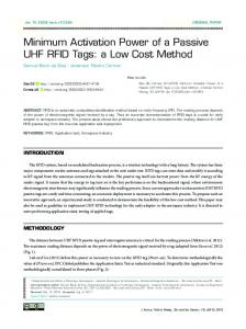
Capacitive Sensing Fig. 6. Picture of PDL on milk carton. The red and black wires Plates extending from the PDL to the bottom of the milk carton are the capacitive sensing plates. The antenna extends along the top of the carton.
Percent Full (%) / Temperature (°C
know when it will be removed from the fridge for use or transferred from a shipping crate or trailer. Two tests were performed with the instrumented milk carton, which is shown in Fig. 6. The first is a controlled experiment where the milk carton is filled with water and dispensed in fixed amounts. The second is an uncontrolled experiment where the milk carton is used by various people in an office environment for tea and coffee drinks. The results of the first experiment are shown in Fig. 7. In this test, a carton was filled with water and poured out in regular increments much like the test in Table I. The difference is that the carton is stored in the fridge between pours, and the water is poured out instead of added. Similar to Table I, the carton is physically separated from other cartons to prevent the sensor from detecting the milk in other cartons. 100
Temperature (°C) Percent Fill
90 80 70 60 50 40 30 20
VII. APPLICATIONS There are a host of potential applications for PDLs. Monitoring sensitive parameters in supply chains is an obvious extension for current RFID networks. In particular, temperature-controlled supply chains for food, chemicals, blood plasma, and pharmaceuticals are target application areas. Shock, vibration, and humidity are other parameters than can be measured for sensitive goods. In addition to logged parameters, PDLs can supplement their sensor data with information provided by RFID readers. Examples include location, time, package contents, and 100 Percent Full (%) / Temperature (C
915 MHz Antenna
Each time the carton is poured, an upward spike in fill percentage occurs. This is caused by the position of the sensor; when the carton is tilted to pour out liquid, the tilting causes the fluid to cover the entire sensor. Positioning the sensor of the opposite side of the carton would cause dips in the level during pouring. Fig. 8 shows an uncontrolled experiment where a milk carton is instrumented the same way as Fig. 7 and used over the course of a day. The high milk consumption is due primarily to an espresso machine near the office refrigerator; one carton of milk makes 10 to 15 lattes. The data in the uncontrolled experiment (Fig. 8) shows two primary differences from the controlled experiment (Fig. 7). First, the carton was not physically separated from the other cartons in the uncontrolled experiment, which caused the level to increase at times when the sensor was near other cartons. Second, the amount of milk removed each time was not regulated in the uncontrolled experiment, so the level changed by varying amounts after each use. By shielding the capacitive sensor, the interference effects of other milk cartons could be eliminated.
Temperature (°C) Percent Full
90 80 70 60 50 40 30 20 10 0
10
0
0 0
2
4
6
8
Time (hours) Fig. 7. Temperature and percentage fill level of a milk carton filled with water over time. Temperature spikes correspond to usages, and the percentage full drops after each use. This control data set was emptied by a prescribed amount during each “use.”
5
10 15 Time (hours)
20
Fig. 8. Temperature and percentage fill level of a milk carton over time. Temperature spikes correspond to usages, and the percentage full drops after each use. There is what looks like considerable noise in the percentage full data, however, the capacitance sensor used to detect fill level is also sensitive to the hand holding the milk carton during usages. Also, the un-shielded capacitive sensor used here can be affected by milk in adjacent cartons, depending on placement.
8 transport vehicle information. Further, this data could easily be provided using the standard Gen 2 RFID “Write” command. Note that storing reader-supplied information be done with any RFID tag (passive, active or PDL) that has unused non-volatile memory, but this information gains value when it supplements logged sensor data. This would allow for detailed information at the destination without the complexity of requiring communication between parties (such as manufacturing company, distributor and retailer). For example, if the temperature exceeded a threshold during transit and the delivery truck license plate number were supplied by the loading dock RFID reader, the problem could be discovered and easily identified. RFID has also been employed for non-conventional applications, which can benefit from PDLs. For example, RFID has been explored for use in eldercare monitoring, allowing caregivers to unobtrusively monitor daily living tasks such as cooking and cleaning [14]. However, data in these applications has typically been limited to the binary visibility model (ie, “is the tag near the reader?”). Using PDLs, an RFID reader in the fridge and pantry cabinets can recharge the tags, and the tags can sense and log data when out of range of the reader. This allows continual data acquisition without the stringent requirement of proximity to a reader. Another application for PDLs is implantable medical sensors. Parameters such as blood pressure, blood sugar, temperature, and heart rate could be monitored and logged throughout the day. At night, a bedside reader would then download the day’s data and charge the PDL. Finally, medical analysis software would allow the user to see the results and submit data to a doctor for professional analysis.
fullness of a milk carton during the course of a day. The results are sufficiently promising that we are looking at larger and different use cases, and we hope that wirelessly-charged tags prove to be a viable model for many applications. REFERENCES [1] [2] [3] [4]
[5] [6]
[7] [8]
[9] [10]
[11]
VIII. CONCLUSIONS The WISP-PDL demonstrates a new power model that differs from conventional passive and active models for powering RFID tags. Like passive tags, PDLs use only the energy that they acquire from wireless signals (via standard RFID readers) to perform tasks. Like active tags, PDLs can continue to operate and collect sensor data when away from an RFID reader. We have achieved this combination by having PDLs charge themselves by harvesting energy from RFID reader signals and storing the energy in a capacitor for later use when they are away from a reader. This model is intended for use in settings such as supply chain monitoring, in which tags have occasional contact with readers. Our prototype WISP-PDL extends our prior work on WISP (a passive, sensor-enabled UHF tag) by adding energy storage and away-from-reader operation. WISP-PDLs run on EPC Gen 2 infrastructure to upload collected sensor data via commercial readers and in a manner that is compatible with standard EPC Gen 2 tags. The short demonstration study we present demonstrates the feasibility of the novel power model. The WISP-PDL successfully monitored the temperature and
[12] [13] [14] [15]
Sample, A.P., Yeager, D.J., Smith, J.R., “Design of a PassivelyPowered, Programmable Sensing Platform for UHF RFID Systems”, IEEE Transactions on Instrumentation and Measurement. To appear. Namjun, Cho, et al. "A 5.1-uW 0.3-mm2 UHF RFID Tag Chip Integrated With Sensors for Wireless Environmental Monitoring". 2005.V 279-82.(Narrijun et al. 4763-66;Kocer and Flynn 1142-48) Kocer, F. and M. P. Flynn. "A new transponder architecture with on-chip ADC for long-range telemetry applications." Solid-State Circuits, IEEE Journal of 41.5 (2006): 1142-48. Polastre, J.; Szewczyk, R.; Culler, D., "Telos: enabling ultra-low power wireless research," Information Processing in Sensor Networks, 2005. IPSN 2005. Fourth International Symposium on , vol., no., pp. 364-369, 15 April 2005 Savi Technology. Savi SensorTag ST-676. Datasheet, 11 June 2006. http://www.savi.com/products/SensorTag_676.pdf Smith, J., Jiang, B., Roy, S., Philipose, M., Sundara- Rajan, K., and Mamishev, A. ID modulation: Embedding sensor data in an RFID timeseries. In Proceedings of The Seventh Information Hiding Workshop (Barcelona, Spain, June 6--8, 2005). Springer-Verlag, Berlin, 2005. Siden, Johan; Zeng, Xuezhi; Unander, Tomas; Koptyug, Andrey; Nilsson, Hans-Erik, "Remote Moisture Sensing utilizing Ordinary RFID Tags," Sensors, 2007 IEEE , vol., no., pp.308- 311, 28-31 Oct. 2007 D. G. Watters, P. Jayaweera, A. J. Bahr, and D. L. Huestis. Design and performance of wireless sensors for structural health monitoring. In D. O. Thompson and D. E. Chimenti, editors, AIP Conf. Proc. 615: Quantitative Nondestructive Evaluation, pages 969–976, May 2002. Want, R. "Enabling ubiquitous sensing with RFID." Computer 37.4 (2004): 84-86. Malinowski, M., Moskwa, M., Feldmeier, M., Laibowitz, M., and Paradiso, J. A. 2007. CargoNet: a low-cost micropower sensor node exploiting quasi-passive wakeup for adaptive asychronous monitoring of exceptional events. In Proceedings of the 5th international Conference on Embedded Networked Sensor Systems (Sydney, Australia, November 06 - 09, 2007). SenSys '07. ACM, New York, NY, 145-159. Seiko Instruments. 2-Wire Realtime Clock S-35390A. http://www.sii-ic.com/en/product1.jsp?subcatID=13&productID=1356 EM Microelectronic-Marin. V3020 Ultra Low Power 1-Bit 32kHz RTC. http://www.emmicroelectronic.com/Products.asp?IdProduct=70 L. K. Baxter, Capacitive sensors: design and applications, IEEE press, 1997. M. Philipose et al., “Inferring Activities from Interactions with Objects,” IEEE Pervasive Computing, October-December 2004 (Vol. 3, No. 4) 2004, pp. 50–57. Brewin, B., “Army to Test Passive RFID Tags on Food Shipments”, Computerworld, Last accessed, 24/10/2004 (2003).