Oct 3, 2016 - and witness header selection. I. INTRODUCTION. Wireless sensor networks (WSNs) have emerged as promising technologies for numerous ...
I.J. Information Technology and Computer Science, 2016, 10, 22-28 Published Online October 2016 in MECS (http://www.mecs -press.org/) DOI: 10.5815/ijitcs.2016.10.03
Witness-Header and Next-Node Selection to Extend Network Lifetime in Energy-Efficient Clone-Node Detection in WSNs Muhammad K. Shahzad and Quang-Ngoc Phung College of Information and Communication Engineering, Sungkyunkwan University, Suwon 440-746, Republic of Korea E-mail: {khuram, ngocpq}@skku.edu
Abstract—Wireless sensor network (WSN) has emerged as potential technology for their applications in battlefields, infrastructure building, traffic surveillance, habitat monitoring, health, and s mart ho mes. Unattended nature of these networks makes them vulnerable to variety of attacks, the inherent stringent resources makes conventional security measure in feasible. An attacker can capture a sensor node to install number of clone nodes with same privacy information causing serious security threats and deterioration in network lifetime. Current, security scheme along with distinct advantages suffer fro m nu mber o f limitations. A good counter attacks measure should not only cater for security and energy efficiency but network lifetime as well. In this paper, we propose a next-node selection method which consider residual energy and clone attacks ratio in addition to distance, in order to overco me the limitation of fixed path based shortest routing. These factors are also considered while selecting the witness header in WSNs. Results demonstrate the efficacy of the proposed schemes in terms of network lifetime.
presented an energy efficient clone detection (ERCD) protocol which also shows improvements in network lifetime. This scheme however, also have some limitat ions; it consider transmission energy but ignores receiver energy consumption, it is based on distance based routing which is based on fixed paths, and it may not work if witness header is dead or compro mised among other. We counter these limitations in our proposed method and further improve network lifetime.
Index Terms—Wireless sensor network, Network protocols, network lifetime, dynamic routing, next node, and witness header selection.
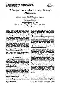
Fig.1. A Clone Attack Scenario
I. INT RODUCT ION Wireless sensor networks (WSNs) have emerged as promising technologies for nu merous applications in civil and military. Secure co mmunication is one of the most challenging and risky tasks. WSNs are found to be prone to clone node attacks that effects in many harmful ways. In a clone node attack, an adversary captures a node and installs its code with same privacy information. Later adversary makes mu ltiple copies of the node and installs them throughout the network to take control of the network. If these clone nodes are not detected, network is left vulnerable to attacks and thus severe damage. A typical clone node attack scenario is shown in Fig. 1. To counter these attacks security measures have been proposed [1-7]. Most of the methods focus on having high detection ratio of these attacks without network lifetime being of major concern. In research [1], authors Copyright © 2016 MECS
In order to balance network energy consumption, next hop nodes for routing and filtering nodes should be dynamically selected. The inputs of the model are energy level, number of hops, and false traffic ratio (FTR). This next hop selection method is used for forwarding node selection in the underlying routing and witness header selection. The original scheme is based on shortest path routing which consider only d istance for selecting next hop forwarding node which is fixed path routing in essence. Our scheme can dynamically opt for different paths based on current energy levels of the candidate nodes. Similarly, for verification or witness node selection, if the fitness value of a node is higher among candidate nodes than it will be witness node with filtering false report capabilities. Th is will help balancing network wide energy usage and thus prolong the network lifetime. In ERCD, the witn ess header is bott le n eck o f the scheme, since after a witness header of a witness ring energy level reaches to zero or co mpro mised, it could not work. In ou r p roposed method at the cost o f mu ltip le witness header management instead o f sing le one, the
I.J. Information Technology and Computer Science, 2016, 10, 22-28
Witness-Header and Next-Node Selection to Extend Network Lifetime in Energy-Efficient Clone-Node Detection in WSNs
verification traffic load balance distributed. This load distribution along with next hope selection method results in more balanced energy consumption approach. Clone node detection or energy-efficiency are not focus of this paper. We proposed energy-aware dynamic routing, next hope, and witness header selection to more evenly distribute the commun ication loads to further extend the network lifetime. Following are the expected contributions of our proposed method as compared to ERCD.
Network lifetime improvements Dynamic path selection Traffic load balancing with mu ltip le witness header
The rest of the paper is organized as fo llows; Section 2 presents an overview of the related work, section 3 shows the system assumptions and system model, the detail of our proposed method is exp lained in the section 4, numerical results based on the analysis and simulat ion is illustrated in section 5, and conclusion and future work at the end of this paper.
II. LIT ERAT URE REVIEW Wireless sensor networks [WSNs] have beco me very popular and ubiquitous technologies for everyday applications. However, there a nu mber of challenges to be addressed for secure commun ication. WSNs are vulnerable to clone node attacks that effects in many devastating ways. To counter these attacks security measures have been proposed [1-7]. Most of the methods focus on having high detection ratio of these att acks without further improving and network lifetime as main concern. In energy-efficient clone node detection (ERCD) protocol in WSNs [1], a location based, clone node detection protocol has been presented. It can grantees clone node detection and have minimal effect on network lifetime. Witness node used in verificat ion of privacy informat ion is randomly selected fro m a ring area to detect these attacks. Ring structure is used for energyefficient data forwarding towards the witness node, witness header, and sink or base station (BS). This distributes the load balance within the network and help in imp roving network lifetime. Analytical and simulat ion results show the efficacy of proposed method which can achieve up to 100% detection with t rustful witnesses. The proposed scheme further studies clone node detection with untruthful witness. With presence of 10% compro mised witnesses detection probability can approach up to 98%. In work [2], a centralized SET approach based on set operations is proposed. It tries to limit detection overhead by computation of set operations of union and intersection of exclusive subsets in the sensor network. SET scheme divide the network into logically separate and non-overlapping regions or clusters controlled by a cluster head (CH). These CHs send reports to BS Copyright © 2016 MECS
23
containing IDs of all nodes in its cluster and itself in the form of a subset. The set operations are performed after computing the subsets. If the intersection of any two subsets if non-empty set a clone attack is detected. The work [3], presents a survey of clone node attacks in WSN. An attacker can physically capture a node and duplicated one or more nodes at strategic locations to control and damage the entire network. The authors study variety of threats specific to clone node attacks and analyses different detection schemes and classify them in different categories. It co mprehensively exp lores different proposals in each category. The discussed schemes are evaluated and there advantages and limitations are highlighted. In research [4], proposes two novel clone node detection schemes. First scheme is distributed hash tables (DTH) and second one is randomly detected explorat ion (RDE) scheme. The simulat ions results verify the protocol design and demonstrate its efficiency in communicat ion overhead and satisfactory detection probability. Recent clone detection schemes such as randomized efficient and distributed (RED) [5] and line-select mu lticast (LSM) protocol [7], fail to guarantee both requirements of use random witnesses selection and a significant probability of clone detection. For examp le; RED protocol attains a high clone detection rate with the assistance of deterministic mapping function in witness selection. Since, a deterministic mapping function is also probable to be compromised, and compro mises on randomness of selection of witness nodes which degrades security. However, in LSM protocol, a source node can randomly select mu ltip le sink nodes and establish paths to those nodes. If a witness node obtains several copies of verification messages from the single source along various paths, it identify it a clone attack which triggers a revocation procedure. LSM results in a low detection probability in case of a small nu mber of witnesses. This is because the intersection of mult iple paths should a witness node which probability is dependent on density of witness nodes. In [6], authors focus on solving the critical problems of energy and memo ry. In order to solve these problems a fast, lightweight, efficient, and mobile agent based security scheme has been proposed against clone node or replicat ing node attacks. Mobile agents are software defined wh ich require minimu m energy usage by nodes. These agent can also cooperate with the outside world for collaboration and self-governing. In [7], a distributed algorith m for clone node detection is presented. The paper focusses the effect of undetected clone nodes and their effect on commun ication overhead and storage cost incurred by each algorithm. An optimization framework has been proposed for selection of clone node detection parameters based on above mentioned cost analysis. Simulations are provided to validate the framework. In this paper, energy d issipation model or first order radio model [8, 9] is used to compare the energy consumption of ERCD and our proposed protocol. A typical sensor node composed of a data processing unit, a
I.J. Information Technology and Computer Science, 2016, 10, 22-28
24
Witness-Header and Next-Node Selection to Extend Network Lifetime in Energy-Efficient Clone-Node Detection in WSNs
micro sensor unit, antenna, radio commun ication components, power supply, and amplifier. In our implementation of the first order radio model, we only consider the energy usage that is associated with the radio component. Moreover, the clocks of the sensor nodes assumed to be synchronized using an energy-efficient time synchronization protocol (ETSP) in WSNs [10]. In research [11] t wo clone node detection schemes based on hash table value and probabilistic d irected diffusion are presented using NS2 simulator. The authors [12] on general network deploy ment graph presented distributed hash table based clone detection scheme. Secure routing scheme was presented [13] by secure directed diffusion protocol. Work [14], p resented a security scheme for wormhole detection at MAC layer in WSNs. The authors in [15], proposed quality of service improvement scheme in WSNs based on symmetric key cryptography schemes.
Table I presents the simulation parameters for the performance analysis in experimental setup.
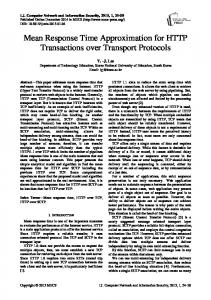
III. SYST EM A SSUMPT IONS AND M ODELS A. System Assumptions Some localizat ion component is assume to present in the system so that after random deployed each sensor node knows its location. This is necessary because, after an event is spotted, its location is required to create the path in order to report the event to the BS. After sensor nodes are deployed, the boot-up process is started with a localization component. We also assume bidirectional co mmun ication links in the sense that both source and sink can send and receive the messages. Each node also possesses a unique ID and also knows its key. Each node has at least one witness nodes which know the privacy information of the orig inal node. Each witness ring has one witness header. All the sensor nodes have a limited and fixed sensing range and contains a battery with a limited and fixed init ial energy of 1 Joule. B. Experimental Setup Model In this paper, we consider a 2000-node randomly distributed sensor network. The simulat ion has been performed in custom built simulator in M icrosoft Visual Studio 2012 using C#. This network is based on ring based topology. The stated network has an area of πr2 m2 with ring based clusters. The sensor nodes are distributed in sectors of the sensor network. All the sensor nodes has a range wh ich is used to determine neighbors and candidate nodes. The is stationary and knows the node IDs and their locations in advance. The sensor field setup used performance analysis is shown in Fig. 2.
Copyright © 2016 MECS
Fig.2. Randomly Deployed Circular Sensor Field. T able 1. Simulation Experiment Parameters Parameter
Value
Number of nodes
2000
Sensor field radius
r=200
Field size
πr2 m2
Base station location
Ring center
Node Range
30 m 50 nJ/bit 100 pJ/bit/m2
Initial node energy
1 Joule
Packet size
200 bits
Path loss constant (λ)
2
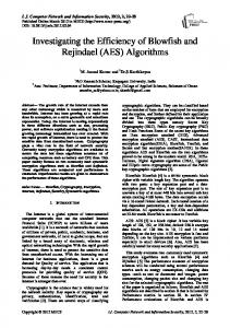
C. First Order Radio Model In this paper, first order radio model or energy dissipation model in [8, 9] is used compare the energyefficiency performance of ERCD and proposed method. A sensor node composed of a radio co mponents, data processing unit, antenna, power supply, a micro sensor unit, and amplifier. In this paper, we only consider the energy consumption that is related to the radio components. A classic, simple, and most utilized energy consumption analysis model is the first-order radio model illustrated in Fig. 3.
I.J. Information Technology and Computer Science, 2016, 10, 22-28
Witness-Header and Next-Node Selection to Extend Network Lifetime in Energy-Efficient Clone-Node Detection in WSNs
25
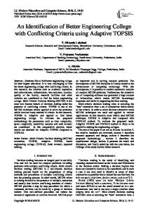
among candidate nodes. A node with highest energy an d closer to the destination will be selected to forward the report. This process will continue until destination is reached. D. Witness Selection A source node A randomly generates witness index for node B. Wi is ring index (Ri) of the witness. Then this node will create a witness node selection message and send it to the node B. After node B received the message node B record the privacy informat ion of the node A which sends a broadcast message to all it neighbors so announce that it is witness node of A. If node A cannot find the witness node in Wi of node B ring than node B forwards witness selection message to farthest left neighbor of it in the witness index ring (Ri). This will continue until witness selection procedure is finished. This process is explained the flow chart presented in Fig. 4.
Fig.3. T he First-Order Radio Model.
For transferring -bit packet over a distance between the transmitter and receiver, the transmission energy ( ) is represented by Eq. (1): (
)
(1)
Where is the energy consumed by the electronics of the circu itry, is the energy utilized by the transmitter electronics to transfer bits, is the energy needed by the amplifier, and λ is the path loss ( ) is the energy required to constant. Similarly, receive k bits: ( )
(2)
IV. PROPOSED M ET HOD OVERVIEW In this section we exp lain the overview o f the proposed method. A. Network Initialization In setup phase all nodes IDs and location information is pre-loaded on every node. BS also knows the location and ids and all sensor nodes in the network. In itializat ion phase and BS are assumed to be secure. B. Neighbour and Witness Discovery Assuming the location component, every node determines its neighbors’ info rmation and distance. This location information is broadcasted to neighbors. Using breadth first search (BFS) the location of the witness header is obtained. Fig.4. Witness Selection Phase.
C. Next Node Selection After an event is detected, the event discovering nodes send reports to the BS. A path is created using an evaluation function which considers energy level and distance of neighbor nodes to select forward ing node Copyright © 2016 MECS
E. Message Verification When a node has data to transmit to the BS, it create a data message, it will send the message to three rings Ri-1, Ri, and Ri+1. After a node in these rings receives a
I.J. Information Technology and Computer Science, 2016, 10, 22-28
26
Witness-Header and Next-Node Selection to Extend Network Lifetime in Energy-Efficient Clone-Node Detection in WSNs
message, if there is no witness node in its ring the message is dropped. In that case message will be forwarded to one of its neighbors that is witness of node A. When a witness of node A, i.e. Aw, receives data message it will check number of conditions for verification of the message. In case witness header is one of its neighbors than data message should be forwarded to it. A number of verificat ion conditions should be met before witness header forward message to BS.
Witness header will check sender ID and location informat ion, if this matches with the values at witness header In case of receiv ing mult iple copies of the message with same privacy information If the t ime stamp of the received message is earlier or equal to the last data message generated drop the message. If not the time stamp for the last message received is updated.
If all the conditions are met the message will be forwarded to BS otherwise clone node is detected and revocation message is generated. The pseudo code for the verification process is shown in the Fig. 5. Step: 1. NodeA create a DataMessage msg Step: 2. Node send the message to it witness ring (ring index is wIndex) and two neighbor ring of the witness ring (ring indexes is wIndex-1 and wIndex +1). Let node1, node2 and node3 is three nodes in the three rings have received message. Step: 3. Foreach Node N in {node1, node2, node3} If there is no witness of NodeA in node n’s neighbors then T he msg will be drop. Else Select a witness node W is one of its neighbors that are the witness of Node A. Forward the msg to W T he next step is described in Step 4, when the message comes to node W. Step: 4. When a witness of nodeA, called W, receives the DataMessage. If the creation time of the msg