Workshop Mobile and Embedded Interactive Systems (MEIS'06) Albrecht Schmidt1, Michael Rohs2, Manfred Broy3 1
Ludwig-Maximilians-Universität München Deutsche Telekom Laboratories, Technische Univeristät Berlin 3 Technische Universität München
[email protected],
[email protected],
[email protected] 2
1 Workshop Theme Interaction with mobile devices and embedded systems has become a part of everyday life. As mobile devices get more sophisticated and embedded systems are increasingly interconnected the creation of usable interactive software poses many new challenges. Issues and opportunities arise from emerging novel paradigms in user interfaces. In particular tangible interaction, device and interfaces ecologies, and implicit interaction create new requirements for user centred design and system development.
2 Topics of Interest • • • • • • • • • • • • • •
novel tangible user interfaces and interaction metaphors new interaction techniques for mobile and embedded interactive systems new interface technologies and concepts sensing and actuator technologies for mobile and embedded interactive systems alternative sensory modalities, e.g. auditory and tactile feedback software models and frameworks methods, tools, models and design guidelines for emerging user interfaces validation, evaluation methods and tools for novel user interfaces experience with complex and compound user interfaces ad-hoc user interfaces for multiple device orchestration ad-hoc interaction with embedded systems via handheld devices prototyping mobile and embedded interactive systems experience of creating everyday objects that become user interfaces experience reports on building, using, and deploying mobile and embedded interactive systems
3 Program Committee • • • • • • • • • • • • • • • • • • •
Elisabeth André, University of Augsburg Patrick Baudisch, Microsoft Research, USA Michael Beigl, University of Karlsruhe Susanne Boll,University of Oldenburg Jan Borchers, RWTH Aachen University Alois Ferscha, University of Linz, Austria Hans Gellersen, Lancaster University, UK Tom Gross, Bauhaus-University Weimar Andreas Holzinger, Universität Graz, Austria Eva Hornecker, HITLabNZ, New Zealand Reinhard Keil-Slawik, University of Paderborn Antonio Krüger, University of Münster Marc Langheinrich, ETH Zürich, Switzerland Ali Nazari, Fraunhofer-IGD, Darmstadt Bernt Schiele, Technical University Darmstadt Norbert Streitz, FHG Darmstadt Manfred Tscheligi, Universität Salzburg, Austria Michael Weber, University of Ulm Jürgen Ziegler, Universität Duisburg-Essen
4 Workshop Proceedings 4.1 Printed Proceedings The printed Workshop proceedings are published by GI in the Lecture Notes in Informatics Series (LNI). 4.2 Online Proceedings The online proceedings are available from the workshop website. Please see http://www.hcilab.org/events/meis06/
Table of Contents
Session: Basic Technologies Toolkit for Bar Code Recognition and Resolving on Camera Phones – Jump Starting the Internet of Things. Robert Adelmann, Marc Langheinrich, Christian Flörkemeier. Institute for Pervasive Computing, ETH Zurich Locating Physical Interface Objects on Interactive Surfaces. Florian Block, Hans Gellersen, Mike Hazas, David Molyneaux, Nicolas Villar. Computing Department, Lancaster University Session: Methods and Concepts Klassifikation der Human-Environment-Interaction in intelligenten Umgebungen. Ali A. Nazari Shirehjini. Fraunhofer-IGD Software Engineering for Ambient Intelligence Systems. Thomas Fuhrmann. Universität Karlsruhe (TH) Tangible Interfaces in Virtual Environments. Johann Habakuk Israel. Virtual Product Creation. Fraunhofer Institute for Production Systems and Design Technology Berlin Social Mobile Interaction using Tangible User Interfaces and Mobile Phones. Karin Leichtenstern, Elisabeth André. Institute of Computer Science. Multimedia Concepts and Applications. Universität Augsburg Session: Prototyping and Evaluation Mobile Map Interaction - Evaluation in an indoor scenario. Hans Jörg Müller, Johannes Schöning, Antonio Krüger. Institute for Geoinformatics, University of Münster The Friday Afternoon Project: A Two-Hour VoodooIO Prototyping Exercise. Nicolas Villar, Hans Gellersen. Computing Department, Lancaster University
Toolkit for Bar Code Recognition and Resolving on Camera Phones – Jump Starting the Internet of Things Robert Adelmann, Marc Langheinrich, Christian Flörkemeier Institute for Pervasive Computing, ETH Zurich {adelmann, langhein, floerkem}@inf.ethz.ch Abstract: Automatic identification technology such as RFID promises to connect physical objects with virtual representations or even computational capabilities. However, even though RFID tags are continuously falling in price, their widespread use on consumer items is still several years away, rendering large-scale experiments with such an “internet of things” difficult. Much more ubiquitous are printed bar codes, yet so far their recognition required either specialized scanner equipment, custom-tailored bar codes or costly commercial licenses – all equally significant deployment hurdles. We have developed a freely available EAN-13 bar code recognition and information system that is both lightweight and fast enough for the use on camera-equipped mobile phones, thus significantly lowering the barrier for large-scale, real-world testing of novel information and interaction applications based on “connected” physical objects. We hope that this “low tech” version of bridging the gap will allow the community to quickly develop and try out more realistic and widespread applications, and thus gain real-world experiences for better jump-starting the future internet of things, today.
1
Today’s Role of Barcode Recognition
The idea of linking real-world products with virtual information has been around for quite some time. In 1998, Barrett and Maglio already described a system for attaching information to real-world objects [BM98], while 1999 Want et al. expanded upon the idea and linked arbitrary items through the use of RFID tags with both information services and actions [WFGH99]. Since then, a number of research projects have continued to explore this concept of “bridging the gap”, i.e., the automatic identification of individually tagged real-world products in order to quickly look up information or initiate a specific action [KBM+ 02]. With the increasing mobility of powerful computing systems, e.g., mobile phones or handheld PDAs, this bridging can even be done in situ, i.e., right when we need it, where we need it. While RFID potentially offers an unprecedented user experience due to its detailed means for identification (i.e., on a per item basis) and the lack of a line-of-sight requirement for reading, most industry analysts agree that an item-level rollout (e.g., having an RFID tag on every single supermarket product) is still several years away [Jue05]. In contrast, the printed bar codes are practically ubiquitous: Virtually every item sold today carries an internationally standardized bar code on its packaging, enabling not only checkout registers to quickly sum up one’s shopping items, but also to identify a product and look up a wealth
of related information. Obviously, using bar codes for linking real-world objects to virtual information has a number of drawbacks when compared to an RFID-enabled future with corresponding mobile RFID readers, such as NFC-enabled1 mobile phones. Due to their sensitivity to soiling, ripping, and lighting conditions, optical bar code recognition can be difficult. Until recently, reading a conventional (i.e., 1D) bar code inevitably required a separate laser scanner or a corresponding mobile phone scanner attachment. The increasing availability of camera phones, i.e., mobile phones with an integrated digital camera, has begun to simplify this process, however. After 2D bar codes have been successfully recognized by most consumer-grade camera phones for quite some time [Roh04], the continuously increasing quality of both the camera resolution and the employed lenses have finally made it feasible to directly read 1D bar codes with such cameras, without the need for special attachments or handheld lasers. This significantly changes the attractiveness of using barcodes for the above physical-to-digital linkage: Instead of waiting several years for a comprehensive item-level roll out of RFID tags, or forcing people to carry around specific scanner attachments for their mobile phones, the support of 1D bar code recognition on any camera phone immediately allows anybody to interact with almost any commercially available product – all it takes is a small application download. The main contribution of this paper is a freely available 1D bar code recognition toolkit that is intended to facilitate the creation of novel applications and services. We believe that the adequate performance of our recognition software, when compared with existing commercial implementations, the ease with which external data sources can be integrated, and the availability of our toolkit under an open source license will help to foster the the use of camera phones as mobile bar code scanners.
2
Related Work
Prior work on using printed bar codes for linking real-world objects with virtual information has often used two dimensional bar codes [RA00, PKA05], which do not use bars of varying widths but instead blocky rectangles that lend themselves much better to low resolutions or misalignments. There is a wide variety of code symbologies available, such as Semacodes, Spotcodes, the Japanese QR-System2 , or Rohs’ VisualCodes [Roh04]. All of these systems were specifically designed to simplify camera-based recognition. However, while they offer both improved detection rates as well as additional services such as range and alignment detection, none of these codes enjoys widespread use, let alone comes close to the billions of products carrying EAN-13 bar codes today. Also, none of these codes is linked to a wealth of EAN-13-indexed information available in online databases today. A number of algorithms have already been implemented for the visual decoding of 1D bar codes on desktop computers3 . Most of these are based on the transformation of the origi1 Near Field Communication (NFC) is a new standard for mobile phones that allows them to both act as an RFID reader and be read by other RFID readers (see www.nfc-forum.org). Many handset manufacturer have already begun shipping NFC-enabled models. 2 See www.semacodes.org, www.op3.com and www.qrcode.com, respectively. 3 See for example www.charactell.com/iRead.html or www.axtel.com.
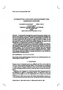
Figure 1: Multiple scanlines: In contrast to existing approaches, we make intense use of multiple scanlines in our algorithm to both increase robustness and improve accuracy. While the image shows all of the scanlines oriented in parallel, our system supports any orientation of scanlines.
nal image information into a decoding domain that simplifies bar code identification, like approaches based on the Fourier transformation or the Hough transformation as proposed by Muniz et al. [MJO99]. These approaches are often used in professional image recognition software, as the offer very good recognition rates. However, their requirements in terms of system resources can be too demanding for typical mobile devices. While both Ohbuchi et al. [OHH04] and Chai and Hock [CH05] have presented algorithms intended for mobile devices, these algorithms so far have not been implemented or tested on actual mobile camera phones. As an alternative to costly domain transformation, a much simpler approach is based on so-called scanlines, which try to detect the bar code along a particular line through the image4 . As such algorithms need much fewer computing resources, they are specifically relevant for the use on mobile camera phones. Their drawbacks, however, lie in their often poor recognition rates when dealing with dirty surfaces, reflections or shadows, or slight misalignments and their need of detecting the bar code in the image first (in order to properly align the scanline). We improved on this by making extensive use of multiple scanlines (see figure 1), which will be explained below in section 3.1. Note that given the commercial potential of the 1D barcode recognition on mobile phones, it is not surprising that a number of commercial solutions exist. Scanbuy offers an application called ScanBuy Decoder5 , which is capable of recognizing 1D barcodes. Similar applications can be bought from PaperClick6 , Gavitec7 , and MediaStick8 , to name but a few. While informal trials with some freely available beta programs from the above vendors showed a comparable, sometimes even superior performance of our system, we explicitly abstained from conducting formal comparisons, as improving the recognition rate or speed is not our primary goal. Instead, we are trying to create a free, easily usable, and robust barcode recognition system for mobile phones, together with an open resolving framework that facilitates rapid prototyping and deployment. The currently available commercial systems, in contrast, not only restrict source-code access but also typically limit barcode resolving to vendor applications and/or a fixed set of lookup services. 4 See
for example sourceforge.net/projects/barcr-reader/. www.scanbuy.com/website/products_decoder.htm. 6 See www.paperclick.com/. 7 See www.mobiledigit.de. 8 See www.mediastick.co.jp. 5 See
3
System Design
Figure 2: Architectural Overview: Our EAN-13 recognition and resolution system consists of a mobile phone application for code recognition, and a server side component for code resolution.
Our EAN-13 bar code recognition and resolution toolkit contains two parts: the barcode recognition component running entirely on J2ME enabled mobile phones that support the MMAPI9 (Mobile Media APIextension) extension and the Java based information server component, which is located on a separate server, to which the detected product code is transmitted via a GPRS (or for local demonstration a Bluetooth) connection. The provided client provides functionality to recognize an EAN13 code, communicate with the server and display the results. The information server uses a plug-in architecture, allowing us to quickly add various services and online information sources (represented as so called “service connectors”). Although this process could also be located on the phone itself, performing them on an external server provides us with greater extendibility, higher flexibility and better performance.
3.1
Recognition Algorithm
In general, our recognition algorithm is scanline based. In order to improve robustness, we decided to not only use a single scanline, but a set of multiple, potentially arbitrarily oriented scanlines (see figure 1). If multiple scanlines cross the bar code, each with a different sensitivity, we can increase the chances that at least one of them will result in a properly recognized code. Also, multiple scanlines can be combined in a majority-voting fashion, were inaccuracies due to dirt or reflections on one line can be compensated by two or more correct identifications on other lines. By applying slightly different recognition parameters along each individual scanline (i.e., the binarization threshold that categorizes pixels into either black or white), the overall recognition accuracy can also be improved. Last not least, by using a variable amount of scanlines, we have a simple mechanism to adapt our algorithm to the processing power of the individual phone it is running on: The more computational capabilities available, the more scanlines and orientations10 we can 9 See
sun.com/software/communitysource/j2me/mmapi/. tests show, however, that most users actually take care to properly align the bar code when using their camera phones, though right-angled rotations (i.e., 90, 180, and 270 degrees) were more common. Especially superimposing our scanlines on the mobile phone’s viewfinder would further guide users to a proper alignment. 10 Initial
Figure 3: Successfully recognized codes: The above pictures show that our algorithm can handle reflections and shadows as well as slightly crumpled paper.
Figure 4: Unrecognized codes: The above three codes are examples of failed recognition attempts. The leftmost image shows a too crumpled bar code; the middle one is angled just too much (we only used horizontal scanline in this experiment); the rightmost image is too blurry.
try. Since the algorithm is scanline based, it cannot cope as well with image distortions as transformation-based algorithms. However, as the analysis below will show, our implementation is sufficiently robust even for lower image resolutions. Also, it is quite fast, has very little memory requirements, and can be implemented relatively easy.
3.2
Performance Evaluation
We have analyzed the recognition performance of our algorithm along two axes: focus and image resolution, as these are currently the two most important parameters influencing recognition accuracy on a mobile camera phone. The camera focus directly affects a picture’s sharpness. Results indicate that focus remains a problem, while low camera resolutions such as 640x480 pixels are not critical. In order to allow camera phones to scan a bar code from close-up, two options are available. Increasingly, camera phones are being equipped with auto-focus lenses that have been developed over the last several years [Tur05, Chu05]. As of spring 2006, most major handset manufacturer offer auto-focus models (e.g., the Nokia N90, SonyEricsson’s K790 and W810, or Samsungs SCH series). Models that still use fixed focus lenses need to be adopted to the required short distance with the help of a macro lens, a cheap accessory that is carried by many mobile phone dealers. Ideally, our system would be deployed on auto-focus systems, thus eliminating the need for any specific hardware accessory. However, macro lenses are cheap and unobtrusive enough to make their use in a large-scale trial seem feasible. For our evaluation, we took pictures of ten bar codes situated on common retail goods. From each code we took 16 pictures, starting with a distance of 10 cm between the code and the camera, and decreasing it in steps of 0.5 cm down to a minimum distance of 2 cm.
Figure 5: Focus and resolution influence: The above graph shows the combined influence of both focus and resolution on the recognition rate when using a macro lens. The innermost dark area indicates an acceptable recognition rate and is situated at about 4–4.5 cm distance between camera and bar code, at a resolution of at least 640x480 pixels.
We used a Nokia N90 mobile phone to take all the pictures with a maximal resolution of 1600x1200 pixels. Since the auto-focus feature of this phone currently can’t be activated neither from a J2ME Midlet nor from a C++ Symbian application, due to the missing functionality in the free libraries provided by Nokia, we used an attached macro lens. From each of the 16 images that were taken at different distances, we created 20 versions in different resolutions (using a desktop image manipulation program). This resulted in a set of 320 images for each bar code. Figure 5 visualizes the influence of the image resolution and camera focus on the recognition success. Results indicate that focus remains a problem, while today’s camera phone resolutions of about 1 MPixel are clearly sufficient for reliable bar code recognition. As pointed out above, however, we expect the market soon to adopt auto-focus not only for high-end devices, but also for common models due to recent technological advances [Chu05, MDK+ 06].
4
Prototypical Applications
In order to illustrate the use of potential of out toolkit, we implemented and provide two prototypical applications. The first prototype represents a simple literature information system, providing information about scanned books, such as their current price or a list of related items (see figure 6). The second prototypical application implements a tool for checking ingredients in nutrition products that could trigger an allergic reaction. Using a retail goods database such as GS111 we could gain access to detailed allergen information of individual products, based on their EAN-13 code. Together with an individual shopper’s allergy profile, the 11 See
www.gs1.org
Figure 6: Example application: The above screenshots show a literature information system – sample application implemented using our recognition and resolution system.
application is able to warn the user of potential allergic reactions to an item with a single click. Given our toolkit, the implementation effort for these two demos was quite low. Changes on the provided J2ME client were limited to renaming issues and took about 5 minutes. Implementing the allergy test application required the implementation of a “service connector” (cf figure 2), providing access to a (commercial) product database, and the implementation of the service component that would generate the result according to a previously defined user profile.
5
Conclusion
Linking the physical world with virtual information is a powerful concept. Even though RFID promises to provide an easy-to-use, pervasive linkage that could easily be accessed with the help of small mobile devices (such as NFC-enabled mobile phones), their use on everyday items such as soda cans or cereal boxes remains unlikely for the next several years. In contrast, regular 1D-bar codes (EAN-13) are ubiquitous – printed on billions of products worldwide and already linked to a wealth of both free and commercial databases. So far, consumer camera phones have in general only be able to recognize specific 2D bar codes, which – just as RFID tags today – have not yet been widely adopted. With the increasing availability of high resolution camera phones, as well as the prospect of cheap auto-focus lenses, using mobile phone to tap into the wealth of EAN-13 product information becomes feasible. This opens up novel ways of fielding systems that explore the “internet of things” – not just for toy applications or small, specially equipped user bases, but for any user with a conventional camera phone, for almost any product, nearly everywhere. In this paper we present the necessary tools for the easy and fast creation and prototyping of own services and applications based on EAN-13 recognition and resolution. They are freely available for download from http://batoo.sourceforge.net/. We hope that this “low tech” version of bridging the gap will allow the community to quickly develop and try out more realistic and widespread applications, and thus gain realworld experiences for better jump-starting the future “internet of things”, today.
References [BM98]
Rob Barrett and Paul P. Maglio. Informative things: how to attach information to the real world. In UIST ’98: Proceedings of the 11th annual ACM symposium on User interface software and technology, pages 81–88, New York, NY, USA, 1998. ACM Press.
[CH05]
Douglas Chai and Florian Hock. Locating and Decoding EAN-13 Barcodes from Images Captured by Digital Cameras. Addendum to Proceedings ICIS2005, 2005.
[Chu05]
Myung-Jin Chung. Development of compact auto focus actuator for camera phone by applying new electromagnetic configuration. In Kee S. Moon, editor, Proceedings of SPIE. Volume 6048 – Optomechatronic Actuators and Manipulation, pages 152–160 (60480J), Sapporo, Japan, December 5, 2005. Intl. Society for Optical Engineering.
[Jue05]
Ari Juels. RFID Privacy: A Tecnical Primer for the Non-Technical Reader. In Katherine Strandburg and Daniela Stan Raicu, editors, Privacy and Technologies of Identity: A Cross-Disciplinary Conversation. Springer, 2005.
[KBM+ 02] Tim Kindberg, John Barton, Jeff Morgan, Gene Becker, Debbie Caswell, Philippe Debaty, Gita Gopal, Marcos Frid, Venky Krishnan, Howard Morris, John Schettino, Bill Serra, and Mirjana Spasojevic. People, places, things: web presence for the real world. Mobile Networks and Applications, 7(5):365–376, 2002. [MDK+ 06] Peter M. Moran, Saman Dharmatilleke, Aik Hau Khaw, Kok Wei Tan, Mei Lin Chan, and Isabel Rodriguez. Fluidic lenses with variable focal length. Applied Physics Letters, 88(041120), January 23, 2006. [MJO99]
Ruben Muniz, Luis Junco, and Adolfo Otero. A robust software barcode reader using the Hough transform. In Proceedings of the 1999 International Conference on Information Intelligence and Systems, pages 313–319, 1999.
[OHH04]
Eisaku Ohbuchi, Hiroshi Hanaizumi, and Lim Ah Hock. Barcode Readers using the Camera Device in Mobile Phones. In CW, pages 260–265. IEEE Computer Society, 2004.
[PKA05]
Lauri Pohjanheimo, Heikki Keränen, and Heikki Ailisto. Implementing Touchme Paradigm with a Mobile Phone. In sOc-EUSAI ’05: Proceedings of the 2005 Joint Conference on Smart Objects and Ambient Intelligence, pages 87–92, New York, NY, USA, 2005. ACM Press.
[RA00]
Jun Rekimoto and Yuji Ayatsuka. CyberCode: designing augmented reality environments with visual tags. In DARE ’00: Proceedings of DARE 2000 on Designing augmented reality environments, pages 1–10, New York, NY, USA, 2000. ACM Press.
[Roh04]
Michael Rohs. Real-World Interaction with Camera-Phones. In 2nd International Symposium on Ubiquitous Computing Systems (UCS 2004), pages 39–48, Tokyo, Japan, November 2004.
[Tur05]
Emily Turrettini. Korean Start-Up Develops Auto-Focus in Camera Phone. Weblog. Available at www.textually.org/picturephoning/archives/ 2005/02/007111.htm, February 2005.
[WFGH99] Roy Want, Kenneth P. Fishkin, Anuj Gujar, and Beverly L. Harrison. Bridging physical and virtual worlds with electronic tags. In CHI ’99: Proceedings of the SIGCHI conference on Human factors in computing systems, pages 370–377, New York, NY, USA, 1999. ACM Press.
Locating Physical Interface Objects on Interactive Surfaces Florian Block, Hans Gellersen, Mike Hazas David Molyneaux, Nicolas Villar Computing Department, Lancaster University Infolab21, South Drive, Lancaster LA1 4WA, U.K. Abstract: Pin&Play has enabled a new type of surface-based physical user interface, characterised by dynamic arrangement of interface objects on a surface area. Previous work has shown that this affords rapid re-arrangement of the spatial layout of interface objects, for example in adaptation to user preferences, but the Pin&Play system did not support tracking of object locations on the surface. In this paper, we investigate and compare two practical location techniques for interactive surfaces that are based on external sensing: detection of surface events using load sensors, and camera-based detection using object beacons.
1 Introduction In a drive to support user interaction and applications beyond the desktop, a wide range of environment-based interface technologies are emerging. Among these, tangible interactive surfaces have received considerable attention, as they extend familiar physical media, such as whiteboards, notice boards and workbenches, with digital interaction [UI97, MSM+ 99, JIPP02]. The Pin&Play project demonstrated a new type of surface-based system in which the surface is augmented as ad hoc network medium for interactive objects [vSG02]. This concept has been extended in the VoodooIO architecture for physical interfaces that afford dynamic re-arrangement of interface objects on interactive surface areas [VGRG06]. The Pin&Play infrastructure is based on interactive surfaces with embedded conductive layers that provide a power and data bus. Physical interface objects can be attached as nodes to the surface (using coaxial pin connectors), and will immediately be discovered on the network bus and registered as part of the interface and henceforth monitored to track user interaction. Like attachment, removal of objects is detected instantaneously. This enables applications, in which the physical composition and spatial layout of the interface can be changed at run time. While insertion, manipulation and removal of objects are tracked by Pin&Play, the infrastructure does not support location of objects. However, knowledge of the spatial arrangement of objects would extend the range of tasks and applications for Pin&Play. In fact, many applications reported for interactive surfaces involve spatial tasks, in which position of objects on the surface, or relative to other objects, is used as meaningful input
[KLLL04]. In this paper we investigate the extension of Pin&Play with techniques for locating objects on the surface. We focus on practical methods that use external sensing, and describe the implementation and characterization of two alternative techniques, one based on pressure sensing and the other using vision.
2 Two Location Methods for Pin&Play An interactive surface with embedded network can be designed to sense location using the same means that provide connectivity to nodes. For example, surface electrodes might be chosen and laid out with a suitable topology [HS02] or resistivity which allows a connected node to be accurately located. However, these methods typically increase the complexity of surface construction or require specialised materials. To facilitate practical manufacture and deployment of our interactive surfaces, we thus investigate two location methods which rely on external sensing systems. This section details the two methods, and then shows how they interoperate with other parts of the Pin&Play architecture.
2.1 Locating surface events using pressure sensing Using load sensors installed on the underside of a surface, it is possible to estimate the position of events which cause the force on the surface to change [SSv+ 02]. Assuming a rigid body mechanical model, the coordinates (u, v) of the point of applied force are linearly dependent on (a) the differential forces detected by the load sensors at the time of the event, and (b) the coordinates where each load sensor contacts the surface. More formally, differential forces Fi are measured from a set of N load sensors which have known locations (xi , yi ), where i = 1 . . . N . The coordinates (u, v) of the force event on the surface are defined as ! ! N N X X Fi Fi xi v= yi . (1) u= PN PN j=1 Fj j=1 Fj i=1 i=1 In our implementation (Fig. 1a), the corners of a 60 × 40 cm board were affixed to four load sensors (manufactured by Bongshin Loadcell) mounted on a vertical surface. Supplied with a DC bias, each load sensor outputs a voltage proportional to the force applied; the maximum measureable load for each sensor is one kilogram. The load sensor outputs are passed through an instrumentation amplifier IC. Using an analogue-to-digital converter, a microcontroller samples each load signal at 300 Hz, and passes the sampled values to a workstation PC via a serial link.
Fig. 1b depicts a typical signal captured from a load sensor as a pin is pushed manually into the board. As the plot shows, the signals captured during a push event are quite distinct. A simple peak detection algorithm can be used to detect the event occurrence. The differential force Fi on a particular sensor is proportional to the average signal level at the top of
1 0.9 0.8
Signal amplitude
0.7 0.6 0.5 0.4 0.3 0.2 0.1 0 0
(a) Load sensor placement
0.5
1
1.5 2 Time (s)
2.5
3
3.5
(b) Typical load signal when a pin is inserted
Abbildung 1: Load sensing for ad hoc interactive surfaces
the peak minus the average signal level before the peak occurred. Note that for the location computation (1), the resulting signal amplitude differential can be substituted directly for the differential force Fi , provided the load sensors have comparable sensitivites.
2.2 Camera-based location of interactive objects Interface objects used as nodes in the Pin&Play system are fitted with a light emitting diode (LED) to provide visual feedback on insertion into a surface. With this output capability, the nodes may be polled to send out a beacon suitable for detection by a camera– based location system. The location system can estimate the position of the LED by using simple image processing to identify significant, highly localised changes in light intensity [KTV+ 05]. A straightforward method of detecting intensity changes is to compute a simple difference between images taken before and after an LED has been turned on. Localising an LED in the difference image yields coordinates referenced to the image itself. For example, the location might be expressed in pixel coordinates. To make the location result useful, it needs to be referenced to the surface on which the nodes are placed. The projective mapping, or homogenous transformation, is a robust technique which models image warping due to camera perspective; it can thus be used to convert between image coordinates and physical coordinates. In a projective mapping, the points on one plane are projected through a single point in space onto another plane [Hec89]. As defined by a two-dimensional projective mapping, the relation between the image coordinates (u′ , v ′ ) and the coordinates on a plane (u, v) is u=
au′ + bv ′ + c gu′ + hv ′ + 1
v=
du′ + ev ′ + f . gu′ + hv ′ + 1
(2)
To convert from image coordinates to physical coordinates for a particular camera setup, the eight coefficients (a through h) must be known. Given four or more unique points in image space and their corresponding points on the physical surface, the coefficients can be determined by reformulating the system of equations using matrix notation, and solving using Gaussian elimination or linear least squares. For details on computing the projective mapping coefficients and a survey of two-dimensional mapping techniques, the reader is referred to Heckbert [Hec89, Sect. 2.2]. Once the LED’s position on the surface has been estimated, it can be related to the location of the node itself, using information about the size of the node and the exact placement of the LED on the node. It is also possible to compute the orientation of nodes equipped with two or more beacon LEDs. The camera–based location system used for the experiments in this paper utilised an offthe-shelf webcam (a Trust SpaceCam 380) with 640 × 480 pixel resolution.1 The webcam and an interactive surface were both connected to a workstation PC, which triggers nodes on the surface to beacon and performs image capture and location estimation. The webcam was placed about 110 cm from the surface, with its field of view covering an area approximately 85 × 64 cm. This yields a physical resolution of about 1.33 mm/pixel.
2.3 Integration in Pin&Play The two location techniques operate in slightly different ways in the context of the interactive surface system architecture. The load sensing method (Fig. 2a) computes a location when a force is applied to the surface, and then associates the result with the node’s ID once the node registers with the system. In contrast, the camera-based method (Fig. 2b) waits for the new node to register, triggers the node to beacon, and then computes a location estimate. Note that both methods rely upon communication with the new node before returning a location result. Thus, false location events, such as those caused by bumps to the surface (for load sensing) or scene lighting changes (for camera-based detection), can often be identified and discarded.
3 Experiments and Analysis A series of location experiments were conducted to aid in characterisation and comparison of the load sensing and camera–based location methods. This section describes these experiments, presents results quantifying the accuracy of the two systems, and then discusses and compares other aspects of the systems’ performance. Readings were taken at locations on a 10 × 7 grid on both surfaces. A grid spacing of 5 cm was used for the load sensing surface, whereas 9 cm was used for the larger surface covered 1 The lenses used in inexpensive webcams often suffer from optical aberrations. Thus, a calibration procedure was performed for the camera, allowing the image processing software to partially compensate for lens effects.
Node Located(node ID, location) Event
Load balance monitoring Significant differential load detected
Location computed
Node Located(node ID, location) Event
Camera captures image
Node ID and location are associated
Node Added(node ID) Event
(a) Load sensing
Request for node to trigger beacon Camera captures image
Node ID and location are associated Location computed using difference image
Node Added(node ID) Event
(b) Camera detection
Abbildung 2: Node location methods in the context of Pin&Play
by the camera. As noted in Sect. 2, both systems require some knowledge, or calibration, which relates the sensor data to the physical surface. For the load sensing system, the sensor locations (xi , yi ) were surveyed manually with respect to the reference grid. To compute the projective mapping as defined by (2) for the camera-based system, two methods were used to find the four points in the image which correspond to the four corner points of the reference grid. First, a one-time manual calibration was carried out by a human to identify the pixel coordinates of the four corners in a captured image. Second, four nodes with beacon capability (i.e. a surface mount LED) were placed at the corner points on the grid, allowing an autocalibration to be performed by the system prior to gathering readings at each location. This autocalibration step involved flashing the LED at each corner node five times, which took approximately twenty seconds in total prior to each experiment. From the resulting difference images, the median pixel coordinates for each corner were used to compute the projective mapping. For the load sensing tests, a tack-shaped node (1.5 cm in diameter) with a single coaxial pin connector was manually pushed into the surface fifty times at each of the seventy locations on the grid, for a total of 3500 location readings. For the camera tests, fifty readings were taken with a tack node placed at each of sixty-six points on the grid, for a total of 3300 location readings.2
3.1 Results Figure 3 shows the error distributions for the two location methods. Although the camerabased implementation covers a larger surface area, it yields significantly lower error. In 95% of cases, the camera-based system was accurate to within 6 mm, compared to 18 mm for the load sensing system. Much of the load sensing error can be attributed to the fact that the system is not perfectly 2 The corners of the grid were not used as test locations for the camera-based system. Readings at these points yield artifically low error, since they are also used for autocalibration.
Percentage of readings with error less than abscissa
100 90 80 70 60 Load sensing Camera (autocalibrated) Camera (manually calibrated)
50 40 30 20 10 0 0
5
10
15 Error (mm)
20
25
30
Abbildung 3: Location accuracy comparison
modeled by rigid body mechanics, as (1) assumes. In our implementation the surface frame and backing are made of inexpensive wood. When a node is pushed onto the surface, visible flexing of the surface occurs. Improved accuracies should be possible by providing added rigidity to the surface. This could be accomplished by using less pliant materials or by adding cross-support beams on the underside of the surface. The results also indicate that manual calibration performs slightly better than autocalibration for the camera system. However, the improvement is about one millimetre at the 95% confidence level, which is comparable to the accuracy with which the reference grid was laid out on the surface.
3.2 Comparative Analysis In this section we briefly analyse other aspects of the systems’ performance in order to contrast the two location methods. Detection Latency. The load sensing method provides location of a node within the time it takes the Pin&Play system to discover and register a node on the surface, and in this sense does not add further latency. The user perceived latency thus equals the time for network discovery of the node, typically under 400 ms, depending on the number of nodes connected. By contrast, node localisation with the camera-based system involves a significant latency in addition to node discovery. In our experiments with camera-based localisation, optimised for accuracy rather than speed, the user perceived latency was 2–3 s. Calibration Needs. The load sensing method requires that the sensor locations be accurately surveyed. The camera method also requires a survey of at least four points in the
image scene. For both systems, a similar amount of time was involved in carrying out this calibration manually. However, if four nodes are connected to the surface at known locations, the camera-based system also offers the option of an unassisted autocalibration without a significant loss in location accuracy. Impact of Node Physical Attributes. In our implementation, both methods make assumptions about node physical attributes in order to compute a location. The load sensing method assumes that the centre of the force applied to the surface corresponds to the centre of the physical node. Likewise, the camera-based method currently assumes that beaconing LEDs are at the centre of the polled node. However, certain nodes may not have these attributes. For example, if a large node is pressed onto the load sensing surface, it is unlikely that the location of the largest force will correspond to the centre of the node. Or, if an LED is positioned away from a node’s centre, then the location of the centre of the node will not be uniquely defined since the orientation of the node on the surface is not known. However, for the case of large or unusually-shaped nodes, camera-based sensing may be the best solution. The exact placement of the LED on the node can be taken into account when interpreting the location estimate. A further enhancement would be to construct nodes using two or more LEDs, making orientation estimable in addition to increasing the reliability of location estimates. Events Prohibiting Location Updates. Commonly in location systems, certain events occurring simultanously with sensor measurements can prohibit the system from returning valid location updates. The load sensing method can fail if a force differential occurs on another part of the surface while a new node is being added. The camera-based method can fail if there are people or objects occluding the beaconing LED at the time of image capture. However the camera-based method can periodically poll nodes in order to refresh the location estimates, whereas the load sensing method can only detect location while the node is being pressed onto the surface.
4 Conclusion We have implemented and analysed two sensing methods for extension of Pin&Play interactive surface with the ability to locate objects as they become attached. Both methods, load-sensing and camera-based localisation, are very practical in terms of implementation and deployment, and provide a level of accuracy that would support disambiguation of objects and a wide range of spatial tasks. Neither of the methods requires any alteration of the core Pin&Play system, and can be added at relatively low cost. The two methods have distinct advantages and disadvantages. Load-sensing allows for very fast localisation of nodes, however with only one try: if the node is not successfully located on insertion the system will not be able to obtain its location until it is removed and re-inserted. Camera-based sensing involves a significant latency but the system can locate nodes at any time following their insertion and is thus able to recover from initial localisation failure. The load-sensing method is well aligned with user interaction, as the act of inserting a node on the surface directly triggers localisation. In contrast, user inter-
action tends to obstruct visual node localisation with the camera-based method. However the camera-based method has the advantage that it can be extended to provide more information, for example to detect object shapes and object orientation in addition to their location. Finally, in terms of deployment, we assume that a camera can be easily aligned with a surface, but the load-sensing method has the advantage can be fully embedded with Pin&Play surfaces, practically as a single unit.
Literatur [Hec89]
Paul S. Heckbert. Fundamentals of Texture Mapping and Image Warping. Diplomarbeit, University of California, Berkeley, 1989.
[HS02]
Frank Hoffmann und James Scott. Location of Mobile Devices Using Networked Surfaces. In Proceedings of UbiComp: Ubiquitous Computing, Seiten 281–298, G¨oteborg, Sweden, September 2002. Springer-Verlag.
[JIPP02]
Robert Jacob, Hiroshi Ishii, Gian Pangaro und James Patten. A tangible interface for organizing information using a grid. In Proceedings of the Conference on Human Factors in Computing Systems (CHI), Seiten 339–346, Minneapolis, USA, April 2002.
[KLLL04]
Scott R. Klemmer, Jack Li, James Lin und James A. Landay. Papier-Mache: toolkit support for tangible input. In CHI ’04: Proceedings of the SIGCHI conference on Human factors in computing systems, Seiten 399–406, Vienna, 2004. ACM Press.
[KTV+ 05] Yasue Kishino, Tsotomu Terada, Nicolas Villar, Hans Gellersen und Shojiro Nishio. Position Detection Mechanism using Camera Images for Pin and SPlay. In Adjunct Proceedings of Ubicomp 2005, Tokyo, Japan, 2005. [MSM+ 99] Thomas P. Moran, Eric Saund, William Van Melle, Anuj U. Gujar, Kenneth P. Fishkin und Beverly L. Harrison. Design and technology for Collaborage: collaborative collages of information on physical walls. In UIST ’99: Proceedings of the 12th annual ACM symposium on User interface software and technology, Seiten 197–206. ACM Press, 1999. [SSv+ 02]
Albrecht Schmidt, Martin Strohbach, Kristof van Laerhoven, Adrian Friday und HansW. Gellersen. Context Acquisition Based on Load Sensing. In Proceedings of UbiComp: Ubiquitous Computing, Seiten 333–350, G¨oteborg, Sweden, Oktober 2002. Springer-Verlag.
[UI97]
Brygg Ullmer und Hiroshi Ishii. The metaDESK: Models and Prototypes for Tangible User Interfaces. In Proceedings of UIST ’97: ACM Symposium on User Interface Software and Technology, Seiten 223–232, Oktober 1997.
[VGRG06] Nicolas Villar, Kiel Gilleade, Devina Ramduny-Ellis und Hans Gellersen. VoodooIO Gaming Kit: A real-time adaptable gaming controller. In ACE ’06: Proceedings of Intl. Conference on Advances in Computer Entertainment Technology. ACM Press, 2006. [vSG02]
Kristof van Laerhoven, Albrecht Schmidt und Hans-W. Gellersen. Pin and Play: Networking Objects through Pins. In Proceedings of the International Conference on Ubiquitous Computing (Ubicomp), Seiten 219–229, G¨oteborg, Sweden, September 2002.
Klassifikation der Human-Environment-Interaction in intelligenten Umgebungen Ali A. Nazari Shirehjini Fraunhofer-IGD Fraunhoferstr. 5, D-64283 Darmstadt, Germany
[email protected] Abstract: Der Begriff Ambient Intelligence (AmI) bezeichnet ein neues Paradigma der Interaktion zwischen dem Menschen und seiner Alltagsumgebung. Ambient Intelligence versetzt diese Umgebung in die Lage, sich des in ihr handelnden Menschen, seiner Ziele und Bed¨urfnisse bewusst zu sein (Context Awareness) und den Nutzer beim Durchf¨uhren seiner T¨atigkeiten zu assistieren. Die vorliegende Arbeit besch¨aftigt sich mit der Frage, wie ein solches Assistieren aussehen soll. Es wird ein detailliertes Modell f¨ur die Klassifikation von Human-Environment-Interaction vorgestellt.
1
Einleitung
Bereits heute leben wir in einer Welt, in der wir von intelligenten Ger¨aten umgeben sind, die uns bei der Gestaltung, Organisation und Durchf¨uhrung unseres t¨aglichen Lebens unterst¨utzen. Es werden immer mehr intelligente Ger¨ate in die Umgebung des Nutzers integriert, welche mit zunehmender Miniaturisierung im Hintergrund verschwinden. Dabei soll die Komplexit¨at der Umgebung und die hohe Anzahl von intelligenten Ger¨aten den Nutzer nicht von seinen eigentlichen Aufgaben abgelenkt. Der Nutzer soll durch die erforderlichen Bedienungsaufgaben kognitiv so wenig wie m¨oglich belastet werden. Der Gebrauch solch umfangreicher, eingebetteter Systeme stellt f¨ur die F¨ahigkeit des Nutzers eine große Herausforderung in intelligenten Umgebungen dar. Je mehr Technik verf¨ugbar ist, desto gr¨oßer wird die Herausforderung f¨ur den Nutzer, Herr u¨ ber seine Alltagsumgebung zu bleiben, und desto mehr sinkt der zus¨atzliche Nutzen von weiteren Ger¨aten. Die Interaktion wird dar¨uber hinaus durch die vielf¨altigen Auspr¨agungen der Technologie, sowie durch sich ver¨andernde Umgebungen erschwert. Betrachtet man solche Umgebungen n¨aher, stellt sich die Frage, wie die Interaktion zwischen dem Menschen und seiner Umgebung intuitiv gestaltet werden kann. Dabei h¨angt die Intuitivit¨at eines Interaktionssystems von der jeweils zu unterst¨utzenden Umgebung und der durchzuf¨uhrenden Nutzeraktivit¨aten ab. Deshalb ist der Entwurf von geeigneten Interaktionsmodellen bei der Entwicklung von AmI-Systemen von großer Bedeutung. Um den Entwurf von geeigneten Interaktionsmodellen zu erleichtern, stellt die vorliegende Arbeit ein mehrdimensionales Klassifikationsmodell f¨ur die Interaktion in reaktiven
Medienr¨aumen vor. Es beschreibt die unterschiedlichen Dimensionen der Interaktion und skizziert den Gestaltungsraum f¨ur den Entwurf von Interaktionsmodellen, so dass das vorliegende Klassifikationsmodell hier auch als ein Metamodell f¨ur die Interaktionsmodellierung dient.
2
¨ Ambient Intelligence Klassifikation von Interaktionsparadigmen fur
Im Bereich der Human-Environment-Interaction lassen sich verschiedene Interaktionsparadigmen unterscheiden, die mit unterschiedlichen Dimensionen klassifiziert werden k¨onnen (vgl. Abb. 1). Einer der wichtigsten Klassifikationsmerkmale ist die Dimension der Initiative. Eine Interaktion kann demnach explizit, implizit oder gemischt erfolgen.
Abbildung 1: Ein Modell f¨ur die Klassifikation der Human-Environment-Interaction.
2.1
Explizite und implizite Interaktion sowie Koexistenz dieser Paradigmen
Generell l¨asst sich die Human-Environment-Interaction in zwei Klassen unterteilen: explizite und implizite Interaktion. Implizite Interaktion kann reaktiv oder proaktiv gestaltet werden. Des Weiteren kann die Human-Environment-Interaction aus einer geregelten impliziten und expliziten Interaktion bestehen, wobei der Nutzer sowohl mittels Assistenzsystemen interagieren kann, als auch durch die intelligente Umgebung automatisch unterst¨utzt wird. • explizit: der Nutzer kann mittels kontextbewusster Assistenzsysteme auf eine intuitiven Art und Weise mit seiner Umgebung interagieren. Dabei bestimmt der Nutzer wann und was geschehen soll. Die Eingaben des Nutzers erfolgen explizit. • implizit - reaktiv: die Umgebung reagiert nach dem Reiz-Reaktions-Prinzip auf das Verhalten des Nutzers und automatisiert einige Vorg¨ange. Hierbei geht es um ein Handeln erst/nur auf Anstoß von außen, aufgrund von Fehlern, M¨angeln, ” Forderungen, im Gegensatz zu aktivem oder proaktivem Handeln“. Bei dieser Art der Interaktion bekommt das System keine direkten Nutzereingaben. Vielmehr l¨osen Nutzerverhalten und Umgebungszust¨ande Systemreaktionen aus. Demnach existiert ein direkter Zusammenhang zwischen Nutzerverhalten und Systemreaktion. • implizit - proaktiv: die Umgebung erkennt vorausschauend (durch die Analyse des Nutzerverhaltens und seiner Umgebung) m¨ogliche Nutzerziele und sch¨atzt seinen Bedarf an ben¨otigter Unterst¨utzung ab. Hierbei geht es um ein fr¨uhzeitiges ” und differenziertes Vorbereiten auf mindestens zwei unterschiedliche Umweltkonstellationen oder bewusstes Gestalten ausgew¨ahlter strategischer Tatbest¨ande...“ (vgl. [Sch00], S. 13). Ausl¨oser von proaktiven Systemreaktionen erfolgen demnach auf Grund von absehbare Nutzersituationen. Bei der proaktiven Interaktion erbringt die Umgebung dem Nutzer ihre Dienste Initiative ergreifend, also ohne dass vom Nutzer eine unmittelbare Eingabe ausgeht, welche einen direkten Zusammenhang zu jenen Proaktivit¨aten h¨atte. Diese Art des Interaktionsdesigns ist an eine Butler-Metapher angelehnt. • Koexistenz von implizit und explizit: Des Weiteren k¨onnen diese beiden Formen koexistieren, wenn z.B. der Nutzer explizite Assistenzsysteme in reaktive Umgebungen hinein tr¨agt und dort zur expliziten Steuerung derselben reaktiven Umgebung einsetzt. Zur Vermeidung von Interaktionskonflikten werden Koordinierungsmechanismen ben¨otigt. Im einfachsten Fall kann dies u¨ ber Floor-Kontrolle erfolgen, wobei entweder nur die reaktive Umgebung oder nur der pers¨onliche Assistent aktiv wird. In anderen Formen kann die Zugriffskontrolle granularer – auf Aktivit¨atsebene oder Ger¨ateebene – definiert und synchronisiert werden. Demnach kann z.B. ein Assistenzsystem in einer Umgebung die Beleuchtung und die Multimedia-Steuerungs-Aufgaben u¨ bernehmen, w¨ahrend die reaktive Umgebung lediglich Aufgaben bezogen auf die Klimaanlage durchf¨uhren darf.
Zu den expliziten Interaktionssystemen z¨ahlen z.B. mobile Interaktionsassistenten, die auf pers¨onlichen Ger¨aten des Nutzers laufen und so den Nutzer in verschiedenen Dom¨anen begleiten und unterst¨utzen. Beispiele hierf¨ur sind das PECo System [Shi05b] oder das Sony InfoPoint-Projekt. Eine explizite Interaktion kann auch mittels gesprochener Sprache und Gesten erfolgen, ohne dass der Benutzer zus¨atzliche Eingabeger¨ate ben¨otigt. Auch im Bereich der impliziten Interaktion existieren bereits signifikante Forschungsarbeiten wie z.B. das SIKOWO oder DynAMITE-Projekt. Gute Beispiele f¨ur Mischformen von einer expliziten und reaktiven Interaktion liefern die Projekte EMBASSI [KHS01] oder SIKOWO [FOR04]. Im Rahmen dieser Projekte hat der Nutzer neben einer expliziten Sprach- und Gesteninteraktion auch die M¨oglichkeit einer reaktiven Interaktion. Eine geregelte Koexistenz mit Konfliktmanagement bzw. Interaktionssynchronisation findet jedoch nicht statt. Umsetzungen des proaktiven Interaktionsparadigmas f¨ur Human-Environment-Interaction existieren selten. Das Aura-Projekt der Carnegie Mellon University hat die Vision von einer solchen proaktiven Interaktion. Der Aura-Vision nach k¨onnte dann das Aura eines Benutzers ihm vorausschauend z.B. die ben¨otigten Informationen beschaffen. Der Nutzer k¨onnte des Weiteren mit seinem Aura u¨ ber nat¨urliche Sprache interagieren und explizit auf Informationen und Dienste zugreifen.
2.2
Zielbasiert und funktionsbasiert
Auf dieser Dimension werden zur Klassifikation der Human-Environment-Interaction die Eingaben des Benutzers in Funktionen (Aktionen) oder Nutzerzielen eingeordnet, welche er gegen¨uber eines Interaktionssystems a¨ ußert. Beispiele f¨ur Funktionen sind ausschal” ten“, einschalten“ oder stumm-schalten“ etc. In der Regel kann dabei eine Funktion ” ” auf eine Operation eines real existierenden Ger¨ates abgebildet werden. Dies ist insbesonders dann der Fall, wenn der Nutzer das funktionsbasierte Bedienkonzept des Ger¨ates mental u¨ bernommen hat [Sen04]. Nicht immer l¨asst sich die ge¨außerte Funktion auf eine Operation abbilden. Es kann sich bei einer ge¨außerten Funktion z.B. um Operationen eines abstrakten Ger¨ates handeln, das zwar im mentalen Konzept des Benutzers existiert, das sich aber nicht in der aktuellen Umgebung des Benutzers befindet oder nicht die gew¨unschte Funktionalit¨at anbietet. So kann der Benutzer z.B. die Funktion DVD ” kopieren“ a¨ ußern, obwohl sich kein DVD-Kopierer, sondern nur ein DVD-Player in seiner Umgebung befindet. Folglich kann in so einem Fall diese Funktion nicht direkt auf Operationen eines Ger¨ates abgebildet werden. Stattdessen k¨onnte ein Ger¨ateverbund diese Funktion ausf¨uhren. Im Gegensatz zur funktionsbasierten Interaktion a¨ ußert sich der Benutzer bei einer zielbasierten Interaktion in Form von definierten Umgebungszust¨anden, welche durch die Ausf¨uhrung von einer Operationsmenge erreicht werden k¨onnen. Dabei interessiert sich der Nutzer in der Regel nicht daf¨ur, durch welche Operationsmenge – Strategie – das gew¨unschte Ziel erreicht wird. So kann der Benutzer das Heller werden“ seiner Umge” ¨ bung w¨unschen, ohne zu bestimmen, ob es z.B. durch Anschalten einer Lampe oder Offnen von Rolll¨aden geschehen soll. Beispiele f¨ur weitere Ziele k¨onnen Pr¨asentieren der letzten ”
Ums¨atze“, Darstellung eines Dokumentes“ oder auch das Beschaffen bestimmter Infor” mationen (z.B. aktuelle Aktienkurse) sein, ohne dabei zu bestimmen, woher sie beschafft und in welcher Form sie pr¨asentiert werden sollen. Es existiert eine Korrelation“ zwischen der Art der Nutzer¨außerungen (Ziele oder Funk” tionen) und der Art der Ger¨ateauswahl (vgl. Kapitel 2.3), um die gew¨unschten Ziele und Funktionen auszuf¨uhren (vgl. [Sen04]). Eine Studie zeigt, dass die Nutzer sich eher in Form von Zielen a¨ ußern, wenn die Ger¨ate st¨arker im Hintergrund verschwinden. Hierbei tritt die Umgebung als ein Ganzes vor. Im mentalen Konzept des Benutzers existiert dann die instrumentierte Umgebung als ein abstraktes Ger¨at, mit dem er zielbasiert interagieren kann (vgl. [Sen04]).
2.3
Ger¨ateorientiert und dynamische Ensembles
Die Dimension der Ger¨ateauswahl unterscheidet die Human-Environment-Interaction danach, ob ein Benutzer ein Ger¨at direkt ausw¨ahlt, das die von ihm gew¨unschte Funktionen und Ziele ausf¨uhren soll, oder die Ger¨ateauswahl selbstorganisierend stattfindet. Im Ge¨ gensatz zu einer direkten Auswahl von Ger¨aten kann der Nutzer seine Außerungen auch an die Umgebung als Ganzes richten, da er in seinem mentalen Konzept diese als ein Ger¨ateverbund wahrnimmt (vgl. [Sen04]). Dabei k¨onnen Ger¨ateverb¨unde – auch spontan gebildete Ensembles genannt (vgl. [EK05]) – dynamisch gebildet werden, um Nutzerziele durchzuf¨uhren. Ein Beispiel f¨ur eine funktionsbasierte, ger¨ateorientierte Human-Environment-Interaction ist das Zeigen auf eine bestimmte Lampe und sprechen des Kommandos ausschalten“ ” (vgl. [FOR04]). In einer etwas dynamischeren Form der Interaktion bestimmt der Nutzer lediglich den Typ des Ger¨ates, welches eine von ihm gew¨unschte Funktion ausf¨uhren soll. So kann der Nutzer bestimmen, dass die Umgebung durch die Benutzug eines Dimmers heller“ werden soll, und dass seine Pr¨asentationsdatei von einem Projektor und nicht ” auf dem Laptopbildschirm dargestellt werden soll. Dabei wird das entsprechende Ger¨at dynamisch ausgew¨ahlt (vgl. [Shi05a]). Eine zielbasierte Interaktion mit einer Umgebung, in der sich Ensembles zwecks Zielausf¨uhrung dynamisch bilden k¨onnen, wird in [EK05] beschrieben. Zwischen der Form der Ger¨ateauswahl besteht eine Korrelation zu einer weiteren Dimension, die untersucht, ob eine Strategie (Operationsmenge) zur Zielausf¨uhrung dynamisch oder statisch gebildet wird (vgl. Kapitel 2.4).
2.4
Makros und dynamische Strategieplannung
Auf der Dimension der Strategiebildung wird bei der Human-Environment-Interaction haupts¨achlich danach unterschieden, ob Funktionsmengen zur Umsetzung eines Zieles dynamisch oder statisch gebildet werden.
Bei einem Makro werden die Ziele des Nutzers stets durch die Ausf¨uhrung derselben Funktionsmenge erreicht. So werden nach der Ziel¨außerung heller“ z.B. immer nur al” le Lampen eingeschaltet und Rolll¨aden ge¨offnet. Eventuelle neue Typen von Ger¨aten, z.B. dimmbare Stehlampen, werden dabei nicht ber¨ucksichtigt. Im Gegensatz zu Makros wird bei einer dynamischen Planung bzw. Strategiebildung je nach den M¨oglichkeiten einer Umgebung und unter Ber¨ucksichtigung von Nutzerpr¨aferenzen ein Plan zur Zielumsetzung gebildet. Diese Strategie kann dann auf Operationen eines dynamischen Ensembles abgebildet werden. Dabei bestimmt die Umgebung, wie eine Strategie f¨ur Nutzerziele gebildet wird. So kann sie f¨ur die Ausf¨uhrung des Zieles Pr¨asentieren der letzten Ums¨atze“ z.B. eine digitale Pr¨asentation auf einem Projektor ” ausw¨ahlen oder aber passende Grafiken ausdrucken und zus¨atzlich die Daten jedem Benutzer per Email zusenden. Beispiele f¨ur zielbasierte Interaktion mittels Makros liefern [Shi05a, Shi05b]. So kann ein Benutzer eine PowerPoint-Datei per Drag&Drop auf ein entsprechendes Pr¨asentations” makro“ seines Bedienassistenten ziehen (vgl. hierzu [Shi05a, Shi05b]). Daraufhin bildet der Bedienassistent eine statische Funktionsmenge auf Operationen von Ger¨atetypen ab, zu deren Ausf¨uhrung zun¨achst passende Ger¨ate per Plug&Play und Device Discovery (z.B. ein Projektionsger¨at mit Pr¨asentationsdienst) ausgew¨ahlt werden.
2.5
Eingabemodalit¨aten
Zur Klassifikation von Human-Environment-Interaction k¨onnen auf dieser Dimension die eingesetzten Formen f¨ur Nutzereingaben sowie Systemausgaben herangezogen werden. Dabei k¨onnen diese auf herk¨ommliche 2D GUI (WIMP) basieren. Ein besonders intuitives Eingabeverfahren – insbesondere f¨ur Device Selection und Pointing – bieten 3DInteraktionselemente. Hierzu geh¨ort z.B. Pen-basierte Interaktion mit 3D-Objekten. Auch hardwarebasierte Gesteneingabe sowie Infrarot- oder Laser-basierte Pointing-Ger¨ate bieten 3D-Eingabem¨oglichkeiten. Sprachkommandos, nat¨urliche (gesprochene) Sprache, nat¨urliche Gesten von Menschen und Mimik-Interaktion sind weitere Modalit¨aten.
2.6
Ger¨ate-, Medien- und Dienstezugriff
Auf einer der wichtigsten Dimensionen wird die Human-Environment-Interaction nach dem Interaktionsobjekt klassifiziert. Dabei gilt es zwischen Systemen zum Ger¨atezugriff, Medienzugriff sowie Dienstezugriff zu unterscheiden. Je nach Interaktionsobjekt kann die Intuitivit¨at einer Bedienmetapher oder die Praktikabilit¨at einer f¨ur Nutzereingabe erforderlichen Modalit¨at stark variieren. So mag eine Sprachkommando-basierte Interaktion mit einem Wetterabfragedienst intuitiv sein. Im Gegensatz dazu k¨onnen Nutzer eine Sprachkommando-basierte Auswahl von Ger¨aten oder durchsuchen von Dokumenten als nicht intuitiv empfinden.
3
Zusammenfassung
Das vorgestellte Modell bildet eine Grundlage f¨ur die systematische Untersuchung und Klassifikation von Konzepten zur Human-Environment-Interaction. Dabei erlaubt das Klassifikationsmodell, die Interaktion in unterschiedliche Dimensionen aufgetrennt zu betrachten. Ein Bedienungskonzept muss unterschiedlichen Anforderungen gen¨ugen. Diese h¨angen zum einen von der Anwendungsdom¨ane und zum anderen von den zu unterst¨utzenden Aktivit¨aten ab. Bei der Entwicklung eines Bedienungskonzepts bietet das vorgestellte Klassifikationsmodell eine Entscheidungsgrundlage daf¨ur an, welchem Interaktionsparadigma das zu entwickelnde Bedienungskonzept folgen sollte. Es existieren bereits Klassifikationsmodelle f¨ur die Human-Environment-Interaction. Nach Sheridan (vgl. [She88]) wird die Interaktion auf den Dimensionen der Initiative und Automatisierungsgrad klassifiziert. Demnach kann bei der Human-Environment-Interaction die Initiative entweder vom System ausgehen oder vom Benutzer ergriffen werden. Auf der Dimension des Automatisierungsgrades klassifiziert Sheridan Assistenzsyseme danach, in wie weit eine Aufgabe vom System u¨ bernommen wird. So kann ein System z.B. informieren, L¨osungswege vorschlagen oder auch vollautomatisch eine Aufgabe ausf¨uhren. Auch der Grad der Adaptivit¨at ist ein Merkmal, das unterschiedlich ausgepr¨agt sein kann. Ein adaptives System passt sich dem Benutzer von sich aus an. Ein adaptierbares System hingegen kann vom Benutzer nach seinen W¨unschen eingerichtet werden (vgl. [NWzK03]). Schmidt et al. stellen in [SKH05] ein Modell vor, wonach die Interaktion des Nutzers mit seiner Umgebung detaillierter klassifiziert werden kann. Darin unterscheiden die Autoren, wie transparent der Nutzer ein System benutzt (explicit use und implicit use). Dabei kann die Interaktion u¨ ber nahtlos in der Umgebung eingebettete Ger¨ate erfolgen oder u¨ ber Interaktionsger¨ate ablaufen. Als Beispiel sind heute bereits automatische T¨ursysteme nahtlos in Umgebungen eingebettet. Der Benutzer kann solche T¨uren implizit benutzen, indem er einfach durch l¨auft und sich die T¨ur automatisch o¨ ffnet. Er kann sie aber auch explizit benutzen, indem er einen Gegenstand in den Sensor h¨alt, damit die T¨ur ge¨offnet bleibt. W¨ahrend Sheridan und Schmidt haupts¨achlich die Art der Automatisierung (Initiative, Automatisierungsgrad, Interaktionstransparenz) ber¨ucksichtigen, behandelt das pr¨asentierte Modell weitere wichtige Aspekte der Human-Environment-Interaction. Nach Sheridan unterscheidet sich ein Assistenzsystem zur zielbasierten Steuerung von Ger¨ate-Ensembles nicht von einem System, das eine rein funktionsbasierte Steuerung von einzelnen Ger¨aten erlaubt. Aus der Sicht des Human-Environment-Interaction stellen jedoch diese Systeme – aufgrund der dargestellten unterschiedlichen Interaktionsparadigmen – v¨ollig unterschiedliche Systeme dar und k¨onnen deshalb mit den existierenden Modellen nicht genauer klassifiziert werden. Im Gegensatz zu [SKH05] und [She88] erlaubt das vorgestellte Modell eine weitergehende und detaillierte Klassifikation von Human-Environment-Interaction.
Literatur [EK05]
Jos´e L. Encarnac¸a˜ o und Thomas Kirste. Ambient Intelligence: Towards Smart Appliance Ensembles. In From Integrated Publication and Information Systems to Virtual Information and Knowledge Environments, Seiten 261–270, Rostock, Germany, 2005. Rostock University. http://www.informatik.uni-rostock.de/mmis/paper.pdf.
[FOR04] FORSIP Research Project. sikowo- Situative und personalisierte Kommunikation mit Wohnkomfortregelsystemen. Web, 2004. http://www.forsip.de/index.php? show=projekte_sikowo&page=1&lang=de. [KHS01] Thomas Kirste, Thorsten Herfet und Michael Schnaider. EMBASSI: multimodal assistance for universal access to infotainment and service infrastructures. In Proceedings of the 2001 EC/NSF workshop on Universal accessibility of ubiquitous computing, Seiten 41–50. ACM Press, 2001. [NWzK03] Julia Nitschke, Hartmut Wandke und Christoph Meyer zu Kniendorf. Unterst¨utzung durch menschliche Experten: Vorbild f¨ur Assistenzfunktionen? Web, 2003. http:// www.embassi.de. [Sch00]
Christian Scholz. Personalmanagement. 5. Auflage, 2000.
[Sen04]
Michael Sengpiel. Mentale Modelle zum Wohnzimmer der Zukunft, Ein Vergleich verschiedener User Interfaces mittels Wizard of Oz Technik. Diploma thesis, FU Berlin, 2004. Berlin, Germany.
[She88]
Thomas B. Sheridan. Task Allocation and Supervisory Control. Handbook of HumanComputer Interaction, Seiten 159–173, 1988. ISBN 0444818766.
[Shi05a] Ali A. Nazari Shirehjini. A generic UPnP architecture for ambient intelligence meeting rooms and a control point allowing for integrated 2D and 3D interaction. In sOc-EUSAI ’05: Proceedings of the 2005 joint conference on Smart objects and ambient intelligence, Seiten 207–212, New York, NY, USA, 2005. ACM Press. [Shi05b] Ali A. Nazari Shirehjini. PECo: 3D-based Interaction with a UPnP Meeting Room. Austria, 2005. OCG. [SKH05] Albrecht Schmidt, Matthias Kranz und Paul Holleis. Interacting with the ubiquitous computer: towards embedding interaction. In sOc-EUSAI ’05: Proceedings of the 2005 joint conference on Smart objects and ambient intelligence, Seiten 147–152, New York, NY, USA, 2005. ACM Press.
Software Engineering for Ambient Intelligence Systems Thomas Fuhrmann Universität Karlsruhe (TH) 76131 Karlsruhe
[email protected] Abstract: AmbiComp is a new research project that will invest about 30 person years into the development of a new and simple software engineering approach for mobile embedded interactive systems. In order to achieve its ambitious goals, it will combine research from different fields such as mobile peer-to-peer networks and operating systems. As a result, developing applications across multiple embedded devices shall be greatly facilitated. Ambient intelligence is the vision that many embedded sensor and actuator devices jointly perform applications that enrich the quality of living and the efficiency of manual labour. In the recent years, especially the European Commission has funded several research projects along this vision. If, however, this vision shall become an everyday reality, we have to simplify the software engineering process for such massively distributed systems of low-resource embedded devices. AmbiComp is a new BmBFfunded research project that aims at providing a simple but powerful basis for writing programs that run on such ambient intelligence systems. Beginning in summer 2006, software engineering experts and distributed systems experts, both from academia and industry, will collaborate to design and create a distributed Java operating system together with an integrated software engineering process. The core of the AmbiComp project is a novel self-organizing routing mechanism, scalable source routing (SSR), which efficiently provides the key-based routing (KBR) semantics for embedded devices with limited resources. With KBR, messages are routed towards hashed identifiers rather than hosts. As a consequence, KBR can address services and objects independent of their actual location. Unlike typical peer-to-peer KBR systems such as Chord or Kademlia, SSR is a genuine network layer routing protocol that selforganizingly provides ad-hoc networking between embedded devices. As has been demonstrated in extensive simulations [1,2] SSR can cope well with mobile devices and ungracefully leaving devices. Moreover, SSR can implicitly build aggregation and distribution trees. The second important building block for AmbiComp is a resource-efficient Java virtual machine (JVM). Originally, it was developed for lab courses with inexperienced students [3]. With its help, students could load their programs onto a SD memory card and insert this card into the embedded device. Debug output and exceptions were shown on an integrated LC display. Compared to the state-of-the-art approach of flashing native programs into a microcontroller, this Java approach greatly simplified and sped up the development process. Furthermore, it turned out that this JVM already provided all basic operating system functionality as it is typically provided by a microkernel: (1) Memory protection is guaranteed by the JVM even in absence of a hardware memory management unit. (2) Processes and threads are supported natively by the JVM. Scheduling can be controlled at the bytecode operation level of the JVM independent of hardware support. (3) Inter-process communication is easy since virtual and physical memories are identical on the JVM level. As a result, this JVM provides a simple but powerful basis to run Java applications on simple microcontrollers.
The AmbiComp project shall combine SSR with this JVM: The JVM separates the memory that is visible to the Java programs from the actual physical memory level. Hence, object references can exploit the full identifier space of the KBR system and thereby seamlessly address remote objects without the need for any external translation mechanism. Moreover, due to SSR’s inbuilt support for mobile nodes, this approach does not need any centralized components such as object brokers or service directories to support node mobility. Furthermore, SSR can automatically route requests to the nearest available service and thereby easily cope with ungracefully leaving nodes. Nevertheless, many research questions are still open. For example, it is still not fully clear how object locking shall be performed in that environment, and it needs to be studied how the effect of ungracefully leaving nodes can be confined to as few applications as possible. In spite of these open questions, we believe that AmbiComp will help to simplify software engineering for interacting mobile embedded devices. The KBR semantics together with the JVM provide an effective basis to hide many aspects of the distributed system. We hope that - as a result - writing software for AmbiComp will become as easy as writing software for a PC. In order to further support the software development process, the AmbiComp project will also develop an Eclipse plug-in that is especially tailored to the needs of developers of embedded interactive applications. Together with application experts AmbiComp shall thus also produce various sample applications. Currently, we are looking for potential application experts from the field of mobile and embedded interactive systems. Owing to the limited space of this extended abstract, we could not discuss related work. Clearly, many recent and not-so recent results provide important contributions to the problems address in the AmbiComp project. For example, a similar routing approach has been proposed recently by an independent group [4]. Other groups have pointed out the benefits of Java operating systems previously [5]. Furthermore, there has been a plenitude of distributed systems developed over the last decades. However, unlike AmbiComp, most of them rely on centralized components. Conclusion: AmbiComp is a new research project beginning in summer 2006. It combines efficient key based routing at the network layer with a lightweight Java virtual machine. Thereby, the AmbiComp approach eliminates several problems that are typical to distributed systems with centralized components. As a result, we expect AmbiComp to provide a simple and powerful basis for the development of applications running on top of a distributed system of small, interacting embedded devices. [1] Thomas Fuhrmann. Scalable Routing for Networked Sensors and Actuators. Proc. IEEE SECON 2005, Santa Clara, California, September 2005. [2] Thomas Fuhrmann, Pengfei Di, Kendy Kutzner, and Curt Cramer. Pushing Chord into the Underlay: Scalable Routing for Hybrid MANETs Universität Karlsruhe (TH), Fakultät für Informatik, Technical Report 2006-12. [3] Thomas Fuhrmann and Till Harbaum. A Platform for Lab Exercises in Sensor Networks. Technischer Bericht - 4. GI/ITG Fachgespräch Sensornetze Zürich, Schweiz, March 2005. [4] Matthew Caesar, Miguel Castro, Edmund B. Nightingale, Greg O'Shea and Antony Rowstron. Virtual Ring Routing: Network Routing Inspired by DHTs, Proc. ACM SIGCOMM 2006. [5] Michael Golm. The Structure of a Type-Safe Operating System. Doctoral Dissertation, 16 September 2002.
Tangible Interfaces in Virtual Environments Johann Habakuk Israel Virtual Product Creation Fraunhofer Institute for Production Systems and Design Technology Pascalstraße 8-9 10587 Berlin
[email protected]
Abstract: Integrating Tangible User Interfaces (TUIs) in Virtual Environments is a promising approach to overcome the rigidity of Tangible User Interfaces (TUI) and to ease Virtual Reality (VR) interaction techniques. Advantages and problems of the integration are being described, especially occlusion, focal displacement and shifting.
1 Introduction An increasing number of applications in several areas show the potential of the Tangible Interaction approach in supporting user’s creativity, deepening the interaction experience and giving full control over the interface to the user. But in contrast to WIMP applications, most current tangible artefacts have no means to change their shape by the system. This might obstruct system developers to accept the concept and thus hinder the spreading of tangible interaction in real production systems and end user’s applications.
Figure 1: Virtual, hybrid and purely physical variants of the same model.
spatially integrated hybrid object control
physical 3D representation
integrated physical/virtual environment digital
forcefeedback
digital 3D representation
tracking system events state
positionTR, orientationTR
positionVE orientationVE shape
model
Figure 2: Extended MCRpd interaction model [UI01] of TUI in Virtual Environments
2 Spatial integration of tangible interfaces into virtual environments Our approach to integrating physical objects in Virtual Environments might be a way to overcome the rigidity of Tangible User Interfaces (TUI). It is similar to Mixed Reality (MR) and Augmented Reality (AR) technologies and focuses on: • Integration of action and perception (input and output) space • Interaction with spatially distributed objects instead of single input devices • Fully functioning tangible artefacts • Hybrid objects (spatially connected physical and virtual, graphical objects, see figure 1) • Integration into working environment with distinct interaction spaces (preferably Holobench systems) • Lightweight interaction (no head mounted displays)
Several hybrid tangible interfaces with flexible 2D graphical output have been described, e.g. bricks [FIB95] and metaDESK [UI97], and several Toolkits have been developed, e.g. iStuff [BRSB03], Phidgets [GF01], Papier-Mâché [KLLL04], which might facilitate the development of (graphically represented) tangible interfaces. For the integration of physical objects into 3D environment, accurate spatial tracking and graphical rendering are needed. Optionally, tangible interfaces might be equipped with interactive control elements such as buttons, sliders, LEDs etc. Furthermore it is possible to augment the objects kinesthetically [KINB05]. Figure 2 shows our approach as an extension of Ullmer and Ishii’s model-control-representation (physical and digital) MCRpd [UI01].
3 Integration problems Integration of tangible interfaces into virtual environments causes some problems, especially occlusion, focal displacement and shifting, which limit the illusion of an integrated virtual environment. Occlusion occurs if real objects block the view onto virtual objects. Focal displacement occurs due to different focal levels of the physical objects (focus on the object at hand) and the virtual environment (focus on the projection plane). Shifting is caused by inaccurate tracking of the tangible object’s position TR and orientation TR which results in gaps between the observed physical objects position and its effects in the virtual environment.
4 Outlook Linking Virtual Reality (VR) technology and Tangible User Interfaces is a promising approach to ease VR interaction techniques and increase flexibility and programmability of TUIs. Future VR interaction techniques will possibly involve distributed physical objects and not rely on single interaction devices. Future TUIs will benefit from the possibilities of virtual environments, their powerful graphical output and their “virtual” laws of nature.
References [BRSB03] Ballagas, R.; Ringel, M.; Stone, M.; Brochers, J.: iStuff: A Physical User Interface Toolkit for Ubiquitous Computing Environments, Proceedings of CHI'03, ACM Press, 2003. [GF01] Greenberg, S.; Fitchett. C.: Phidgets: Easy Development of Physical Interfaces through Physical Widgets, Proceedings of UIST'01, ACM Press, 2001. [FIB95] Fitzmaurice, G.; Ishii, H.; Buxton, W.: Bricks: Laying the Foundations for Graspable User Interfaces. In: Proceedings of the CHI’95. New York, USA, ACM, 1995; pp. 442-449. [KINB05] Krause, F. L.; Israel, J. H.; Neumann, J. and Beckmann-Dobrev, B: A 6-DOF User Interface for Grasping in VR-based Computer Aided Styling and Design. In: Proceedings of the ACM Symposium on Virtual Reality Software and Technology (VRST), Monterey, CA, USA, ACM Press, 2005; p. 110-112.
[KLLL04] Klemmer, S. R.; Li J.; Lin J.;Landay, J. A.: Papier-Mâché: Toolkit Support for Tangible Input. In: CHI Letters, Human Factors in Computing Systems: CHI2004, 2004. [UI97] Ullmer, B.; Ishii, H.: The metaDESK: Models and Prototypes for Tangible User Interfaces. In: Proceedings of UIST’97. New York, USA, ACM Press, 1997; pp. 223-232. [UI01] Ullmer, B.; Ishii, H.: Emerging frameworks for tangible user interfaces. In (Carroll, J. M. ed.): Human-computer interaction in the new millennium. Addison-Wesley, Reading, Massachusetts, USA, 2001; pp. 579-601.
Social Mobile Interaction using Tangible User Interfaces and Mobile Phones Karin Leichtenstern, Elisabeth André Institute of Computer Science Multimedia Concepts and Applications Eichleitnerstr. 30 D-86135 Augsburg {Leichtenstern; Andre}@informatik.uni-augsburg.de Abstract: This ‘work in progress’ paper presents an investigation of mobile input devices and interaction techniques on their effects on social engagement for children when interacting with virtual characters. We call interactions social mobile interactions if they increase social involvements. Social mobile interactions are collaborative interactions to create social experiences between children in a group as well as social engagement with the virtual characters. We describe our first findings of adequate input devices and interaction techniques which might support social and emotional learning for children. The tangible user interface (TUI) called Display Cube and a mobile phone interaction technique called touching are discussed on their efficiency creating social interactions and engagement. Finally, we describe our future work including planned user tests.
1 Introduction Children use a special way to interact with things surrounding them. These things imply both objects of the real world and objects of the virtual world. Children’s mental model of how things works as well as their physical skills and social engagement are often different from adult’s ones. These aspects must be considered when developing childrencomputer systems. Current input devices such as a keyboard and a mouse do not consider children’s special needs. Smets describes in [9] that children encounter difficulties when interacting with traditional input devices and a 2D screen, because action and perception are spatially separated. Children want to use technologies which support their curiosities, their love of repetition and their need for control as Druin points out in [1]. One way to find appropriate devices and interaction techniques is developing systems which are hands-on but which supports interesting and innovative interactions which enables social interactions and engagement. In the following, we present first ideas on interactive technologies for children in the interdisciplinary EU project e-Circus [2]. The project investigates how social learning may be enhanced through interactive role play with virtual characters that establish empathetic relationships with the learners. It creates interactive stories in a virtual school with embodied conversational agents in the role of bullies, helpers victims etc. The children run through various bullying episodes, interact with the virtual characters after each episode and provide advice to them. By taking on the perspective of the virtual characters, the children should come up with a better understanding of how to
cope with such situations. Our objective is to investigate how different input devices and interaction techniques affect social learning. We suppose arranging collaborative interactions in a group increases social interactions between children and fosters social skills.
2 Social mobile interaction The most challenging part of our work is finding new and innovative interaction techniques and devices building social skills for children. If an interaction device is used in a mobile fashion, collaboratively, hands-on and creates social skills, we call this interaction social mobile interaction. Social mobile interactions should address the human-human-interaction between children within a group as well as the human-computer-interaction between children and the computer system. The question is how to build social interactions. We suppose that collaborative interactions increase social experiences between children in a group as well as a social engagement to a virtual character of a role-playing game. Collaborative decisions force children to discuss about the scenario and the virtual characters to know about the attitude of the other children. Furthermore, they have to talk about pro and contras to arrive at a decision about an appropriate advice for virtual characters. To enable collaboration and communication between children, the input device should support arrangements enabling discussions and a collaborative decision. Moreover, input devices should support mobility and display functionalities. Mobility allows children to hand around the device and to walk around while interacting with the computer system. Mobility means a more natural and immersive interaction. Display functionalities allow children to receive more and detailed information which might enrich their discussion. Finally, we suppose that interactions with real world objects can increase the immersion of the children and increase the social engagement to virtual characters. For our project, children can interact with two kinds of physical objects of the real world. Physical objects can even represent different suggestions or the virtual characters of the roleplaying game. The representations of all suggestions give children a mnemonic of possible advices. Once they have decided to advice one of the suggestions they can easily interact with the real world object to perform their selection. The other kind of physical objects of the real world are representations of virtual characters. A representation of the virtual characters in the physical world might be a way to provide annotations. In this way they can get background information about the respective virtual character, e.g. more information about the bully to understand his behavior. Thus, we suppose interactions with the real world can enrich the scenario and increase the immersion.
3 Input devices for social and emotional learning Elementary, we need input devices and interaction techniques to support a selection of children’s suggestions for a virtual character. However, to achieve a social engagement, devices and techniques are required to support collaborative interactions to increase interpersonal communication and social interaction between children. Stanton describes in [4] an evaluation between children’s collaborative work. Her results show that using only one input device per group might increase communication between members of a group whereas one device per child increases the effectiveness to perform a certain task but normally decreases the social contact between the children. Moreover, Stanton points out that one child might dominate the decision making when using only one input device. We decided to use a single input device per group to investigate the children’s behavior. We want to see if it implies collaborative decisions and increase children’s attendance to communicate. We introduce and compare two different input devices which are aimed on the children’s needs. We suppose that the introduced Display Cube particularly considers needs of younger children with reading impairments in an age of 7 up to 9 years because it is more easy and intuitive to use whereas mobile phones are addressed to older children who are used to a mobile phones usage. In contrast to TUIs, mobile phones offer a wider range of interactions and more detailed annotations to characters or the episode. The mobile phone can be used as selection and information device. It can display information on the mobile phone regarding any real or virtual object. The information functionality might enrich the experiences for the children which could increase their social engagement for the virtual character. 3.1 Tangible User Interface (TUI) Tangible user interfaces (TUIs) seem to be appropriate for a usage as interaction device in context of social mobile interactions. Generally, TUIs are physical objects of children’s everyday life. They aim to provide direct manipulations by mapping between behaviour of the tool and usage of such a tool and between semantics of the representing world (the control device) and represented world. Normally, they are mobile and not restricted to a single user. Moreover, their manipulations are familiar and intuitive. Holleis and colleagues developed a tangible learning appliance, the so-called Display Cube [3] as displayed in Figure 1. First experiments have shown that the shaking and turning of the cube helped to engage children in learning tasks and fostered interaction between them. We therefore consider the Display Cube as a promising interaction device for e-Circus. However, in our case, the objective is not to teach vocabulary or math. Instead, we use the cube as a collaborative input device in an interactive story telling environment that should increase social skills and affective engagement of children.
On the different cube sides the Display Cube visualizes suggestions, such as tell an adult, children can propose to a virtual character. Children in a group can hand around the cube, switch the sides and discuss about the different options. Finally they can collaboratively decide for an advice to the virtual character and perform the selection by shaking the cube when the preferred suggestion is lying on the top. The children do not only interact with each other, but also with the virtual characters that are displayed on a large screen and may express, for example, doubts regarding the feasibility of the advice given by the children and ask for another tip or repeat their request for help if the decision-making process takes too long.
Figure 1: Display Cube
Using the Display Cube as a means to select among several options, the children may decide collaboratively how the story evolves (even though it is not guaranteed the character always follows their advice). Thus, in our point of view the Display Cube might be an appropriate device for social mobile interactions. 3.2 Mobile Phones Another useful input device in context of social mobile interactions might be mobile phones. Mobile phones and their sensors offer a range for new and easy to use interaction techniques. A NFC [5] reader as provided for the Nokia 3220 [6] can be used to implement the mobile interaction technique called touching. Figure 2 shows the Nokia 3220. Touching requires real world objects which are augmented with RFID tags. A child performs a selection by simply touching a physical world object with the mobile phone. Afterwards the mobile phone can display hints and background information, e.g. more detailed information about the respective virtual character. In this way the mobile phone becomes a guide and selection device in a social interaction context. The combination of the virtual and the real world enrich the interaction experience which addresses children needs for control and curiosity. Almost every physical object of the real world might be used as representation of the virtual world.
We are currently developing several prototypes. For the first prototype we decided to use the so-called circle of decision which is displayed in figure 3. This circle is split in different parts representing different suggestions children can advice to the virtual character. During the scenario children can sit around a table and discuss about the suggestions of the circle. The can turn around the circle to discuss advantages and disadvantages of each option. This arrangement can increase the social interactions between the children and their social engagement. Once they have collaboratively decided, a child selects the respective part of the circle by touching it with the mobile phone. This interaction is quite easy to use.
Figure 2: Mobile Phone as Interaction Device
For another mobile phone prototype we extended the first prototype by using physical objects as representations of the virtual characters. Each of the virtual physical objects is augmented with a RFID tag. Once a child wants to receive annotations to a character it simply touches the physical objects and gets information on the mobile phone.
Figure3: Circle of Decision
The combination of the virtual and the physical world might enrich the experience of the children. It should enable interesting and innovative interactions for the children. In our point of view these interactions enable playful and hands-on interactions for children which increase collaborations. Apart from touching we are planning to investigate more aspects of the mobile phone interaction. Currently, we are investigating other mobile phone sensors and their usage. The Nokia 3220 supports access to a 2D accelerometer. This information can be used to implement a tilt sensitive user interface. We are planning to implement such a user interface for our work.
4 Related Work Until now, research in areas of TUIs and mobile phone interactions has mainly addressed the usability of the system and economical aspects but not the social part of the interaction. However, several of these works is related to our research. Välkkynen describes in [7] the mobile interaction technique called touching. He firstly used this technique to interact with physical objects. Lampe [8] is also working in areas of real world interactions using mobile devices. He built an augmented knight’s castle. Children can receive annotations to physical objects when touching them using a mobile phone. In this way he enriched a traditional toy environment with additional information. Sheridan [10] investigated the cube as TUI. She found affordances of the cube as 3D object and possible manipulations, based on action, description and events.
5 Conclusion and Future Work In this paper we introduced our first findings of input devices and interaction techniques on their efficiency in creating social experiences and engagements. We called this kind of interaction social mobile interaction. We described requirements for a social interaction between the human-human-interaction as well as the human-computerinteraction. An appropriate interaction device and technique must support mobility and collaborative decisions of children in a group. Moreover, we suppose that interactions with the real world can help to increase the social engagement to virtual characters. Input devices and interaction techniques depend on the children’s age and skills. Therefore, we introduced the Tangible User Interface Display Cube for children in an age of up to 10 years with reading impairments and the mobile interaction technique touching for children older than 10 years. Both input devices supports mobility, display functionalities, collaboration, communication and real world interactions which are quite necessary for social mobile interactions in our point of view.
We are planning to evaluate prototypes of the introduced input devices and interaction techniques on their effects on social engagement for children. Thereby, we want to discover if children feel more engaged when using new forms of interaction devices and interaction techniques instead of using traditional input devices. Thus, our evaluation is going to compare social interactions provoked by traditional input devices with social interactions provoked by new forms of interaction devices and techniques. Apart from the evaluation of the two introduced devices, we are currently trying to find other social input devices, interaction techniques and interaction scenarios to increase a social engagement for children when interacting with virtual role playing games.
References [1] [2] [3]
[4]
[5] [6] [7]
[8]
[9]
[10]
Druin, A.: The Design of Children’s Technology. Moran Kaufmann Publishers. 1999. E-Circus: http://www.e-circus.org/. Kranz, M., Holleis, P. and Schmidt A.: A Display Cube as a Tangible User Interface. In: Adjunct Proceedings of the Seventh International Conference on Ubiquitous Computing. Tokyo, Japan, September 2005. Stanton, D., Neale, H. and Bayon, V.: Interfaces to Support Children’s Co-present Collaboration: Multiple Mice and Tangible Technologies. In: Computer Supported Collaborative Learning. Taipei, Taiwan, June 2002. NFC Forum: http://www.nfc-forum.org. Nokia 3220 NFC Solution: http://europe.nokia.com/nokia/0,,76314,00.html. Välkkynen, P., Korhonen, I., Plomp, J., Tuomisto, T., Cluitmans, L., Ailisto, H. and Seppä H.: A user interaction paradigm for physical browsing and near-object control based on tags. In: Human Computer Interaction with Mobile Devices and Services. Udine, Italien, September 2003. Lampe, M., Hinske, S. and Brockmann, S.: Mobile Devcies based Interatcion Patterns in Augmented Toy Environments. In: Pervasive 2006 workshop on Pervasive Gaming Applications (PerGames 2006). Dublin, Ireland, May 2006. Smets, G.J.F., Stappers, P.J., Overbeeke, K.J. and Van der Mast, C.A.P.G.: Designing in Virtual Reality: Implementing Perceptual-Action Coupling and Affordances. In: Proceedings of the Virtual Reality Software and Technology Conference. Singapore, August 1994. Sheridan, J., Short, B., Van Laerhoven, K., Villar, N., Kortuem, G.: "Exploring Cube Affordances: Towards A Classification of Non-Verbal Dynamics of Physical Interfaces for Wearable Computing". Eurowearables 2003.
Mobile Map Interaction - Evaluation in an indoor scenario Hans J¨org M¨uller, Johannes Sch¨oning, Antonio Kr¨uger Institute for Geoinformatics, University of M¨unster, Robert-Koch-Strasse 26-28, 48149 Muenster, Germany {joerg.mueller, j.schoening, antonio.krueger}@uni-muenster.de Abstract: Providing indoor navigation within a building is usually associated with large investments in infrastructure. We present and evaluate an approach to provide indoor navigation with minimal infrastructure investments. In our approach people use a mobile camera device like a mobile phone as a magic lens. When the device is sweeped over a map of the building, the way is augmented on the camera image of the map. We show that people using our system use more maps and make less errors. The main advantage of our approach is that no tracking of the user is needed - the navigation is solely based on the user’s mobile phone and paper maps.
1
Introduction
Everyone can remember a situation when he entered an unfamiliar building looking for a certain person. Probably the room number is known, but the unstandardized building plans are difficult to read. The signs pointing to certain departments are difficult to interpret, and many people fall back to social navigation and ask someone. But if the building is big, it is improbable that the person asked knows the way. In the scenario we propose the first action upon entering the building would be to take one’s mobile phone and point it to the next building map. It would be possible to select the person one is looking for from a list or a poster with the employees’ photos. The way to the selected person would then be displayed on the camera image of the buildings’ map. If maps are provided at all decision points within the building, the correct way would always be available. To evaluate our approach we implemented a prototype of the system on an OQO 1 and tested the prototype with users of different familarity levels with the building.
2
Related Work
The system presented in this paper is based on our previous work on augmenting digital information on paper based maps [1]. The magic lens approach we implemented is presented in [4]. In order to track the camera device in map coordinates, we use an optical 1 www.oqo.com
marker based tracking approach [2, 3]. The marker-based approach requires printed markers on the physical map, which need to be visible in the camera image. This approach is very robust and has the main advantage that no special infrastructure is needed. Reily [5] uses physical maps equipped with RFID tags to provide additional information on a mobile device, which means that a RFID reader is needed on the mobile device.
3
Implementation and Interaction Schema
The prototype is implemented in Java and runs on an OQO. We installed an USB camera on the back of the OQO to simulate a mobile phone with a camera. The camera image is superimposed with the path and directions the user needs to take. The user can interact with the application with a pen. The user can select persons he wants to visit from a list. When the device is pointed to a map the current location of the user is highlighted with a red dot. Note that, because the location of the map is encoded in the marker, no additional localization technology is needed. In addition, the path from the current position to the goal is augmented on the map. The device can be sweeped, tilted and turned freely over the map. Zooming is natural by moving the device towards and away from the map (see Figure 1).
Figure 1: Usage of the mobile camera device.
4 4.1
Evaluation Test Scenario
The evaluation took place in the building of the institute for geoinformatics in M¨unster. We recruited 25 participants at the age of 19-27 for the study (21 men, 4 women), most of them students of M¨unster University. We divided the participants into 3 categories depending on their spatial familiarity with the building: Beginner, Medium, and Expert. Beginners were not familiar with the building and visited it for the first time for the purpose of this study, most of them were students from other departments. Medium users already knew parts of the building and were mostly students from our department towards the end of their first year. Experts were familiar with all floors and most parts of the building. This group consisted mainly of master students in their last year from our department. The test was carried out with a group equipped with a mobile camera device (12 users: 4 Beginners, 4 Medium, 4 Experts) and a control group (13 users: 4 Beginners, 4 Medium, 5 Experts) which had no such device available.
4.2
Test Setup
Figure 2: Screenshot of the application.
The starting point for all users was our lab. The goal for all participants was to find the way to the room of the fictive faculty member Mr. Smeagol. To reach the destination they had to travel through two floors. Along this way four paper based map have been attached to the walls nearby critical decision points. In order to allow easy identification the maps were marked with a blue iconic information sign (see Figure 1). The current location was
marked on the map with a red dot (”You are here”). Both participant groups could use these maps to orient themselves in the building. Of course the usage pattern for the group with the mobile camera device differed from the patterns of the control group. 4.2.1
Mobile camera device group
At the start point of the navigation users were briefly introduced to the application running on the mobile camera device. Users had to select the name of the target person from a list (see Figure 2). Afterwards they were told, that at each of the four maps in the building, the mobile camera device could provide them with a map overlay showing the way from the current location to the target destination. During the navigation task users were free in using the camera device with the maps (see Figure 1). In case of a navigation error, i.e. when users took a wrong turn, the experimenter interacted and put the user back on the right path. 4.2.2
Control group
Users without the devices received a list with persons and their associated rooms at the laboratory. Since they had no visualization of the path, they had to infer that information from the maps alone. Navigation errors were handled in exactly the same way as discussed in the previous section. 4.2.3
Variables
The independent variables of this evaluation were the technology type (mobile camera device versus no device) and the spatial familiarity (Beginner, Medium, Expert). The dependent variables were the time needed, the number of accessed maps, and the number of errors. Time was measured from the first view on the map to the arrival at the destination.
5
Results
On average all users needed 158 seconds to complete the wayfinding task from the lab to Mr. Smeagol’s office, they made 1.4 mistakes and used on average approx. 3 maps (out of 4). The average orientation time was similar for both groups, but the variability of orientation time for the camera device group was clearly higher. Presumably this effect was caused by the different level of familiarity to this type of mobile device (although we have not asked participants explicitly about this). The control group made significantly more errors on average (t-Test, p < 0.05) and the variability of the error rate was much higher than in the group with the mobile camera device. The group of mobile camera device users was able to lower the number of errors by about 60% (see Figure 5). Also the number of maps used was by 25% significantly higher (p < 0.05) in the camera device group than in the control group (see Figure 4). Since earlier studies with indoor maps have
Total time 300
total time (sec.)
250
200
150
100
50
0 with
without
mobile camera device
Figure 3: Comparison of the total wayfinding time between users with and without a mobile camera device. The graphs show box plots with mean value, 25% and 75% quartiles, and min/max values.
Number of used maps 4,5
number of used maps
4 3,5 3 2,5 2 1,5 1 0,5 0 with
without
mobile camera device
Figure 4: Comparison of map usage of users with and without a mobile camera device. The graphs show box plots with mean value, 25% and 75% quartiles, and min/max values.
Error rate 6
5
# errors
4
3
2
1
0 with
without
mobile camera device
Figure 5: Comparison of the error rates between users with and without a mobile camera device. The graphs show box plots with mean value, 25% and 75% quartiles, and min/max values.
indicated that users have problems with schematic indoor maps in general [6], this problem might be reduced when providing dynamic map overlays with concrete way instructions. It was slightly surprising that the control group was on average 10 seconds faster (although not significant) than the device group (see Figure 3). One possible reason could be the fewer maps used by the control group and that errors had no big influence on the overall wayfinding time (since users were interrupted and put back on the right track). Not very surprisingly spatial familiarity had a clear effect on the number of errors. The higher the spatial familiarity was the lower the amount of errors during the wayfinding task (see Figure 6). When looking at the data for Beginner users in the camera device group, it is interesting to note that they made approx. the same amount of errors as the Medium users of the control group. A similar relationship exists between the Medium users of the camera device group and the Expert users of the control group.
6
Summary and future work
In this paper we have presented the results of a preliminary user study looking at the effects of a navigation system that uses paper based maps and a mobile camera device overlay. The results show that using such a dynamic overlay increases navigation performance by reducing navigation errors. Most of our interpretations are still speculative, but we believe that this study gives a first idea of the usefulness of such a simple indoor navigation system based on mobile camera device. We plan to extend our studies to outdoor scenarios and will take into account the effect
Figure 6: Comparison of spatial familiarity classes and error rates. The graphs show box plots with mean value, 25% and 75% quartiles, and min/max values.
of the familiarity with the mobile device. In the presented experiments wayfinding time could not be used to measure navigation performance since errors had no influence on it. We will try to redesign the experiments in a way that wayfinding time would gain more expressiveness. Finally we are planning to transfer our results to outdoor navigation scenarios (mainly with city overview maps) and would like to carry out another user study with a more complex navigation task involving more maps. As we said, the main advantage of our approach is that no tracking infrastructure is needed, and we believe that the cheap and easy installation at sites makes our approach very promising.
7
Acknowledgments
Thank to Jan Torben Heuer, Georg K¨ohler, and Nicolai Pohl for helping us running the tests.
References [1] Sch¨oning, J., Kr¨uger, A., M¨uller, H.J.: Interaction of mobile camera devices with physical maps. Adjunct Proceeding of the Fourth International Conference on Pervasive Computing, (2006) [2] Rohs, M.: Real-world interaction with camera-phones. 2nd Intl.Symposium on Ubiquitous Computing Systems (UCS 2004), (2004) [3] Rohs, M., Roduner, C.: Camera Phones with Pen Input as Annotation Devices. Proceedings of the Workshop PERMID, (2005) [4] Bier, E. A., Stone, M. C., Pier, K., Buxton, W., DeRose, T. D.: Toolglass and magic lenses: The see-through interface. Computer Graphics, vol. 27, no. Annual Conference Series, pp. 7380, (1993) [5] Reilly, D., Welsman-Dinelle, M., Bate, C., Inkpen, K.: Just Point and Click? Using Handhelds to Interact with Paper Maps. Proceedings of the 7th international conference on Human Computer Interaction with Mobile Devices and Services (2005) [6] Klippel, A., Freksa, C., Winter, S.: You-Are-Here Maps in Emergencies - The Danger of Getting Lost. Journal of Spatial Science, 51 (1): 117-131. (2006)
The Friday Afternoon Project: A Two-Hour VoodooIO Prototyping Exercise Nicolas Villar, Hans Gellersen Computing Department, Lancaster University Infolab21, South Drive, Lancaster LA1 4WA, U.K. {villar,hwg}@comp.lancs.ac.uk
Abstract: VoodooIO is a new architecture for physical user interfaces, providing interface devices that can be flexibly arranged on an interactive substrate. The architecture supports rapid assembly of physical interfaces and dynamic rearrangement of devices. In this paper we provide an account of a case study in which VoodooIO was used to rapidly build and explore a physical interface to an existing application, Google Earth. The case study gives insight into VoodooIO’s support for rapid prototyping of physical user interface applications.
1 Introduction Rapid prototyping of interfaces is an important step to test design ideas very early in the process. For GUI applications a plethora of tools are available that let designers rapidly construct and modify interfaces in order to explore design alternatives. However as computing moves from screen-based toward more tangible interaction, it becomes a challenge to provide comparable support for rapid prototyping of physical user interface applications. VoodooIO is a novel architecture for physical user interfaces that we develop with the aim of making physical interfaces more malleable, in the sense that they can be rapidly assembled and re-configured. The architecture is based on physical controls that can be flexibly arranged on an interface substrate, and has been implemented based on the Pin&Play concept of networking devices through surfaces with embedded conductive layers [VSG02]. Figure 1 shows a selection of devices and the substrate material. The set of interface devices is comparable to the components provided by the Phidgets toolkit [GF01] but it is a distinct property of VoodooIO that the devices can be very easily inserted and removed from the interface using sharp coaxial pin connectors. In previous work we have shown how VoodooIO facilitates interface adaptation at runtime, for example in interfaces to music software [VLG05] and games [Vi06]. In this paper we focus on the use of VoodooIO for rapid prototyping, and provide an account of a case study in which VoodooIO was used to build a physical interface to the Google Earth application. This prototyping exercise highlights two aspect of VoodooIO: its support for rapid construction of a physical interface to existing software; and the flexibility it provides for exploration of different physical interface configurations.
Fig. 1. VoodooIO provides devices that can be flexibly arranged on an interactive substrate.
2 A Physical Interface for Google Earth Google Earth allows a user to browse a collection of satellite imagery spanning the whole surface of the globe, making it possible to point and zoom to view any place on the planet (Fig.2, left). The resolution of some of the imagery is astounding, and after initial exploration on a desktop computer we sketched ideas for a larger-scale interface using physical controls in conjunction with a wall-mounted projection surface. After playing with Google Earth for a while, we found the most interesting actions to be zooming and panning (others include rotating the image, jumping to a specific place, and adding place-markers) – and decided to provide a VoodooIO interface to control these parameters. Below is a sketch of the interface idea (Fig 2, right). The Google Earth screen (without graphical controls) is projected onto a wall-mounted VoodooIO substrate. Four VoodooIO buttons allow the user to pan over the image, and are intended to work like the arrow keys on the keyboard. Notice how the button at the top actually makes the image scroll downwards, or the button at the left makes the image scroll to the right. This is the same effect that would result from using the arrow keys - much like pressing the down-arrow in Word causes the text to scroll upwards - and is a convention of graphical user interfaces. The fourth control is a rotary knob that controls the zoom level of the image.
Fig. 2. Google Earth on the desktop (left) and our design sketch for a physical interface (right).
3 Prototype Implementation A trick that we have often used to interface VoodooIO control events to an existing program is to write a small application that generates keystrokes for the target application in response to VoodooIO interaction events. For this exercise we picked four VoodooIO buttons, and for each one, mapped their Pressed / Not Pressed states to simulate Key Up / Key Down events of a virtual keyboard. Below is an extract of the event handler that is executed whenever a VoodooIO button generates an interaction event. if (buttonNode.GetID().Equals("378F8")) { if (buttonNode.IsPressed()) { keybd_event(KEY_LEFT_ARROW, 0x45, KEYEVEN_KEYDOWN, 0); } else { keybd_event(KEY_LEFT_ARROW, 0x45, KEYEVEN_KEYUP, 0); } }
By default the arrow keys can be used to pan across the Google Earth visualization, so the application needed no modification. Mapping a VoodooIO knob to the Zoom In/Out function was only slightly more involved. Rotating the knob to the right causes a virtual ‘+’ key to be pressed, which causes Google Earth to zoom in. Rotating it to the left generates a virtual ‘-‘ key down event, and rotating the knob to a middle position generates a ‘+’ and ‘-‘ key-up events (equivalent of releasing the physical keys) and bringing the zooming to a halt.
As an afterthought we also picked up two Slider devices, and using the same three-state mapping as the zoom knob (back-stop-forward) we mapped one to the Left/Right arrow key events and the other to the Up/Down arrrows. Sliding one slider to one side left causes the image to scroll continuously to the left, slide it to the other end and the image begins to pan to the right. This was quickly implemented and tested on a VoodooIO tablet (Fig 3). The complete implementation and debugging time was about an hour.
Fig. 3. Desk prototype using a VoodooIO tablet.
4 Deployment of the Prototype Once everything was working we copied the VoodooIO mapping program onto a memory flash drive, grabbed the buttons, sliders and dial and headed down to the XS lab. We loaded the program onto a machine in the lab, which is connected to a large wall-mounted VoodooIO notice-board and to a steerable projector. We downloaded and installed Google Earth, steered its image onto the board, ran the VoodooIO application and things began to work (Fig. 4). The setup of the system, from the time of going down down to the lab, took about thirty minutes to get everything in place and working.
Fig. 4. Dave tests the system after deployment in the lab.
5 Testing and Exploration We had originally arranged the four “arrow” buttons on the board as in the original concept sketch. As Dave, a colleague in the lab, tried it, he very quickly mentioned that the mapping felt wrong, and we could understand what he meant: pressing the button on the right caused the image to scroll to the left, as it had done sensibly on the desktop computer screen – but now, in the context of a larger and more immersive display it felt wrong. We physically switched the left and right buttons around, so that pressing on the right-hand one caused the image to scroll to the right. Note that no software remapping of button-to-action took place, we simply rearranged the physical arrangement of the controls to achieve this in a few seconds. To our surprise, the new mapping felt much more natural, so we swapped the up and down buttons around as well. Is this a result of the interaction being situated over the visualization, rather than separate from it as in a keyboard/screen situation? – We had not intended to explore this particular effect but the flexible arrangement of controls as supported by VoodooIO will make it easy to study different user preferences. During this time Martyn, another colleague was carrying out some ultrasonic data collection in the XS lab, and while waiting for the process to finish he became an unsuspecting user-tester of the interface. The buttons remained in their place, and the zoom dial was attached to the lower-right hand corner of the board, as in the original sketch (Fig. 5, left).
Fig. 5. The layout of controls as originally sketched (left) and interface occlusion (right) He was able to pan and zoom in and out using the controls, although the interaction seemed slightly uncomfortable at times. For example he was standing to the left of the board most of the time as to not occlude the projected image, except when reaching for the zoom dial (Fig 5, right). Also, he is left-handed so manipulating this control with his right was not ideal. So he unfastened the zoom dial from its original position and attached it instead to the top left corner of the board (Fig 6, left). Problems solved.
Fig. 6. The zoom dial quickly repositioned (left) and trying out a slider for panning (right)
We then suggested that instead of using the buttons to pan he try one of the sliders that I had also brought down with me. He attached the vertical-scroll slider alongside the left side of the board, underneath the zoom control (Fig 6, right). He tried scrolling with it, found that the mapping was “reversed” (I didn’t catch whether it was the same one that Dave and I found unnatural, but which is natural in GUI window scroll bars) so he simply unfastened the slider, turned it 180 degrees, and attached it again.
An added advantage of using the sliders over the buttons was the fact that you could set the map to drift in a particular direction without having to keep a button constantly depressed, which allowed one to step back and appreciate the effect of flying over the landscape. Martyn then added the second (horizontal) scroll slider, oriented underneath and perpendicular to the first one (Fig 7, left). Finally the now redundant buttons were removed to clear up the display area – they weren’t being used anyway now that the sliders appeared to be a better way of panning around (Fig 7, right).
Fig. 7. Adding a second scroll slider for panning (left) and removing the buttons (right)
6 Conclusion This prototyping exercise demonstrates how VoodooIO can contributing to fast development of application ideas for physical interfaces. The result is not bad for the two hours that it took to put together and test the original concept! But more importantly this exercise highlights the flexibility that VoodooIO provides to designers and users: it allows exploration of interface configurations in very fluid manner – devices are just added, removed, or repositioned in order to modify the user experience without need for reprogramming, recompilation, or stopping and restarting of the application. Notice how much the interface in Fig. 7 differs from the sketch in Fig. 2. We believe that the end result wasn’t necessary better than the original design but it is safe to say that it was better suited to Martyn’s preferences for many reasons. One of them being the fact that he is left handed and his arrangement better suits his ergonomic preference. The ability to try, compare and exchange different types of control on-the-fly also yielded interesting results. This is only made possible because the physical aspects of the architecture are just as flexible as the software that it is supported by and integrated with. With the flexibility provided by VoodooIO, it begins to approach the idea of a “blank piece of paper” that users and interaction designers can be presented with to sketch out their own physical interfaces.
References [GF01] S. Greenberg and C. Fitchett. Phidgets: easy development of physical interfaces through physical widgets. Proc. UIST ’01: User Interface Software and Technology, ACM Press (2001), 209–218. [VSG02] Van Laerhoven, K.; Schmidt A.; Gellersen, H.: Pin&Play: Networking Objects through Pins". Proc. of 4th Intl. Conf. on Ubiquitous Computing (Ubicomp 2002), Gothenburg, Sweden, LNCS No. 2498, Springer Verlag, pp.219 - 229. [VLG05] Villar, N.; Lindsay, A.; Gellersen, H.: Pin&Play&Perform: A Rearrangeable Tangible Interface for Musical Compostion and Performance Proc. NIME ’05 (New Interfaces for Musical Expression), Vancouver, 2005. [Vi06] Villar, N. et al.: VoodooIO Gaming Kit: A real-time adaptable gaming controller. Proc. of ACM International Conference on Advances in Computer Entertainment Technology (ACE 2006), Hollywood, June 2006, ACM Press.