Sequence diagram for the pervasive health care scenario. run a workflow process, ... diagrams, the following invoke instantiates a local user interface process running ...... [19] N. Russell, A. H. ter Hofstede, W. M. van der Aalst, and N. Mulyar.
Formalizing Higher-order Mobile Embedded Business Processes with Binding Bigraphs? Mikkel Bundgaard, Arne John Glenstrup, Thomas Hildebrandt, Espen Højsgaard, and Henning Niss IT University of Copenhagen, Denmark {mikkelbu, panic, hilde, espen, hniss}@itu.dk
Abstract. We propose and formalize HomeBPEL, a higher-order WSBPEL-like business process execution language where processes are firstclass values that can be stored in variables, passed as messages, and activated as embedded sub-instances. A sub-instance is similar to a WSBPEL scope, except that it can be dynamically frozen and stored as a process in a variable, and then subsequently be thawed when reactivated as a sub-instance. We motivate HomeBPEL by an example of pervasive health care where treatment guidelines are dynamically deployed as sub processes that may be delegated dynamically to other workflow engines and in particular stay available for disconnected operation on mobile devices. We provide a formal semantics based on binding bigraphical reactive systems implemented in the BPL Tool as part of the Bigraphical Programming Languages project at ITU. The semantics is an extension of a semantics given previously for a simplified subset of WS-BPEL and exploits the close correspondence between bigraphs and XML to provide a formalized run-time format very close to standard WS-BPEL syntax, which also constitutes the representation of frozen sub-instances.
1
Introduction
Services implemented and orchestrated by processes written in languages such as WS-BPEL are being put forward as a means to achieve loosely coupled and highly flexible computer supported business and work processes. In the current architectures, services are deployed and managed on web servers by meta-level tools and cannot be replaced or moved during the life-time of a session with an instance of the service. In the present paper we propose and formalize a higher-order WS-BPEL-like language where processes are values that can be stored in variables and dynamically instantiated as embedded sub-instances. A sub-instance is similar to a WS-BPEL scope, except that it can be dynamically frozen during a session and stored as a process in a variable. When frozen in a variable, the process instance can be sent to remote services as any other content ?
This work was funded in part by the Danish Research Agency (grant no.: 2106-070019, no.: 274-06-0415 and no.: 2059-03-0031) and the IT University of Copenhagen (the TrustCare, CosmoBiz and BPL projects).
of variables and dynamically re-instantiated as a local sub-instance continuing its execution. We envisage a use of HomeBPEL where the necessary services or even active instances can be dynamically moved to a local process engine running on a mobile device and thereby allow for disconnected operation. We exemplify this use by an example of pervasive health care, where treatment workflows are moved between and executed locally on mobile devices belonging to either the doctor or the patient, depending on whether the guideline requires actions by the doctor or it prescribes actions carried out as self-treatment by the patient. The investigation is part of the Computer Supported Mobile Adaptive Business Processes (CosmoBiz) project [11], which aims to provide a fully formalized runtime engine for a WS-BPEL-like business process language extended to allow for mobile and adaptive processes. Our primary goals of the formalization is 1) to be able to guarantee that the implemented engine actually conforms to the semantics and 2) to form a basis for the development of type systems that can be used to statically guarantee safe and reliable behavior. To achieve the first goal a main concern is to limit the gap between the source language, its formalization, and the implementation. A key element to achieve the second goal is to strive for a compositional formalization supporting subsequent formalization of type rules for the individual parts. We want to stress that it is not a main concern at this point to provide techniques or principles for verification of processes, which has been the main concern of most WS-BPEL formalizations so far. However, we do hope that future reasoning techniques developed for bigraphs can be employed also to support formal verification. We build on and extend our previous work described in [12, 2] which exploits the close correspondence between bigraphs and XML to provide a small step rewrite semantics of non-trivial subsets of WS-BPEL using a representation of the state of active process instances which is very close to the XML syntax of WS-BPEL processes. We define the semantics in the BPL Tool1 developed in the Bigraphical Programming Languages project which supports visualization and simulation of the execution. The extensibility of bigraphical reactive systems enables us to formalize HomeBPEL as an extension of a formalization of a WSBPEL subset, simply adding formalization of the syntax and semantics for the new primitives for mobile, embedded sub-processes. The syntax and semantics is inspired and guided by our work on the Homer process calculus of Higherorder mobile embedded resources [10, 4, 3]. Not surprisingly, the new features add to the complexity of the language and its formalization. Yet, the formal approach ensures that they are completely unambiguously specified. Also, the close relationship to semantics of process calculi such as Homer and the Mobile Ambients gives a very succinct formalization of sub-process mobility. Indeed, the serialized representation of a mobile process is just a process description. In particular, this means that a future implementation could use the standard XML format for serialized process instances. 1
See hhttp://tiger.itu.dk:8080/bplweb/i
The structure of the paper is as follows. In Sec. 2 we motivate HomeBPEL by an example of pervasive health care. Sec. 3 briefly reviews the definition of binding bigraphs and the BPL tool term language for such, and in Sec. 4 we provide the formalization of higher-order mobile embedded sub-processes as it is defined in the BPL tool. Finally, in Sec. 5 we conclude and propose future work. Related Work. Sub-processes have been proposed by IBM and SAP in [15] as an extension to WS-BPEL (called BPEL-SPE) to allow for modularization and reuse of process fragments to ease the burden of designing large business processes. As argued in [15] one could simulate some of the behavior of subprocesses by invoking another process instead of invoking a sub-process. However, this makes it impossible to establish any coupling between the life-cycles of the two process instance, e.g. enforcing that a sub-process exits if the super process exists prematurely. The sub-processes we propose in this paper extends the proposal in [15] in several aspects. First and foremost, BPEL-SPE requires that the sole interaction of a sub-process is an initial receive activity, and a last reply activity, basically making the sub-process act as a method or function call. We allow that the sub-process can communicate unrestricted with the parent process (and vice versa) using invoke-receive. Furthermore, we add facilities for “freezing” and “thawing” sub-processes as well as (sub-)process mobility. Higher order workflow models applied to health care processes have been considered in the context of Higher-Order (Petri) Nets [13], allowing sub-processes (nets) as values (tokens), which may be dynamically composed. The approach in [13] differs from ours in several ways: Firstly, the approach in [13] is based on Petri Nets as opposed to process calculi, and has no direct relationship to WS-BPEL nor service orchestration. Another central difference is that we execute sub-processes as sub-threads and they can themselves contain sub-processes, whereas in [13] a sub-process is executed step-by-step by the super process and cannot contain sub-processes itself. Finally, the model in [13] allows for dynamic modification and composition of sub-processes, which is not yet supported in our setting. Our formalization of the core WS-BPEL subset relates to the WS-BPEL process calculus given in [16]. An advantage to our approach is that we can reuse the general theory developed for bigraphical reactive systems, instead of redeveloping an entire theory of a new process calculus. As in [16], we hope to be able to equip our formalization with WSDL-like (or even richer) type systems. As described above, our proposal of higher order mobile sub-processes relates to our work on the higher-order process calculus Homer. The Homer calculus is related to the process calculus of Mobile Ambients [5], the Seal calculus [6] and the higher-order π-calculus (HOπ) [20]. Indeed, HomeBPEL shares with Seal and HOπ the combination of name (link) and process passing.
2
Motivating HomeBPEL
In this section we motivate the use of HomeBPEL with a simplified example of workflow management for pervasive health care. Each doctor is assumed to
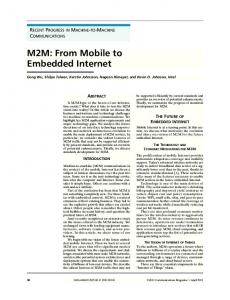
Fig. 1. Sequence diagram for the pervasive health care scenario.
run a workflow process, which is initiated when he/she is hired. Every new treatment of a patient causes a new workflow process to be initiated, describing the clinical guideline to be followed for the particular treatment of the patient. In a centralized solution, this process would be running as a separate workflow on the workflow server and only be available when connected to the network. In HomeBPEL business processes can be manipulated as first class values, so we can let the doctor’s workflow process execute the treatment process as a subprocess. By assuming that the doctor carries a mobile device running its own HomeBPEL engine the treatment process can be executed independently of the network. Moreover, if each patient is equipped with a mobile device running a self-treatment workflow process, the doctor may delegate the treatment process (or parts of it) by sending a sub-process to the patient’s workflow process. A sequence diagram illustrating a simple example of this scenario is shown in Fig. 1. The two large boxes represent the patient’s and the doctor’s PDA respectively. The dotted continuation of the ”life-line” of the sub-process guideline indicates that it is the same process continuing its execution at the patient’s PDA. The BPMN diagram in Fig. 2 gives a more detailed view of the patient process, with a group of guideline sub-processes indicated in the dashed box in the middle. Fig. 3 shows the corresponding HomeBPEL process for the patient. We have left out details related to the data-flow which are not relevant for this example. The initial receive on the hospitalized operation is used to invoke the patient process, as indicated by the createInstance attribute. We have only formalized synchronous communication, so most receive operations are immediately followed by a ”dummy” reply. As also shown in the sequence and BPMN diagrams, the following invoke instantiates a local user interface process running on the patient’s PDA which we assume takes care of handling the task list of
Fig. 2. BPMN diagram of the patient workflow process.
the patient. It is followed by a WS-BPEL flow, which contains two while-loops executing in parallel. The first while-loop (corresponding to the right-hand loop in the BPMN diagram) allows for arbitrarily many self-treatment sub-processes to be received and instantiated: The receive on the run operation waits for a message containing a process and stores it in the input variable guideline. The following activity thaw is part of the new features introduced in HomeBPEL and it is used to create an instance of a process stored in a variable and execute it as a sub-instance within the scope of the corresponding subLink (in the example named subinsts) of the current running instance. The second while-loop forwards messages received from the guideline sub-processes by the HomeBPEL receiveSub activity to the user interface, and in turn forwards the answer back to the sub-process by the HomeBPEL replySub activity. The doctor’s workflow process shown in Fig. 4 also invokes a user interface process, and contains an identical loop for forwarding messages from treatment workflows to the user interface process (which we have omitted from the example code to save space). However, different from the patient workflow, the first step of the main loop of the doctor workflow is to receive a link (on the patient operation) which is then dynamically assigned to the patient partner link by the copy operation. Thereby the doctor workflow process can be dynamically linked to different patient workflow processes during its lifetime. The following thaw activity instantiates a treatment guideline as a sub-process from the variable named guideline. Fig. 5 shows an outline of the treatment process consisting of two phases: A consultation phase invoked explicitly by the doctor and carried out within the doctor’s workflow, and a self-treatment phase carried out within
... ... ... Fig. 3. Patient workflow process.
the patient’s workflow. To initiate the first part of the treatment, the operation consultation is invoked from the doctor workflow by the action invokeSub. The reply of this operation signals that the consultation is finished, and the treatment process is ready to be frozen (by the freeze action) and sent to the patient’s workflow process. Note that we have not specified the specific tasks for each phase in the treatment, which in general could be part of an arbitrarily complex workflow. How-
... ... ... Fig. 4. Doctor workflow process. ... Fig. 5. Treatment guideline process.
ever, we have illustrated how tasks in each phase can be scheduled at the user interface of the current super workflow by invoking the task operation by the invokeSup action. This shows how context-dependent communication is elegantly facilitated in HomeBPEL. One could easily imagine that the treatment processes could also access local information, e.g. special expertise of the doctor or relevant characteristics of the patient. The above example is of course still highly simplified. One would most likely want more control over the behavior of sub-processes, i.e. to disallow malicious processes from entering ones mobile device, to only allow processes from known, trusted sources, etc. We expect to address these questions in future work. A necessary first step is a formal semantics of the execution which will be provided in the following sections.
3
Binding Bigraphs
In this section we briefly review the binding bigraphs of Milner and Jensen [14] and introduce the syntactical representation of binding bigraphs as implemented in the BPL Tool. For a complete introduction to bigraphs we refer to [14]. Binding Bigraphs. A binding bigraph is a pair of graphs: a place graph and a link graph. The place graph is an n-tuple of finite, unordered trees. Except for roots, every node is labelled by a control and has two finite ordered sets of respectively free and binding ports. The link graph is essentially a hypergraph connecting every free port of the nodes in the place graph to either a closed link, a binding port, or a name in a finite set X of names. Jointly with a collection of pairwise disjoint sets Xi ⊆ X of local names, one for each root in the bigraph, the set X defines the (outer) interface of the link graph. The so-called scope condition enforces that any binding port and any name in a set Xi is only connected to ports nested strictly inside the node of the binding port and root i respectively. What we just described above is known as ground binding bigraphs. Intuitively, one may think of a ground binding bigraph as an ordered tuple of terms of a process calculus up to structural congruence: Sibling nodes in the place graph represent processes combined by an associative and commutative parallel operator. Each node is a prefix, and each control denotes a distinct prefix operation (e.g. send or receive in the π-calculus) with free and binding ports representing names and name binders of the particular operation (e.g. for the π-calculus, any node labelled by a send control would have 2 free ports, while nodes labelled by a receive control would have one free and one binding port). The link graph then maps each name in a prefix to either a local name (closed link), a binder (i.e. a binding port) or a name in the interface. A ground bigraph with a single root is also similar to the data model for XML, with controls playing the role of the names of XML elements, ports playing the role of attributes and the linking of ports playing the role of attribute values. As we will see below, we exploit this similarity to give a bigraphical semantics to HomeBPEL resembling closely the XML syntax.
A central ingredient of the theory of bigraphs is that bigraphs in general are (multi-hole) contexts that can be composed: The place graph has a finite ordered set of holes (referred to as sites in the usual bigraph terminology), each associated as a child of a node. The link graph has a set of local names Yi for each hole. As for the outer interface, the sets Yi are pairwise disjoint and contained in a finite set of names Y which jointly with the sets Yi forms the inner interface. As the free ports, the names in Y are connected to either a closed link, a binding port or a name in the outer interface. ~ Xi, Outer (resp. inner) interfaces of binding bigraphs are thus triples hn, X, where the width n is a finite ordinal representing the number of roots (resp. ~ is an n-tuple of pairwise disjoint subsets sites), X is a finite set of names, and X of X which declares some of the names in X as local to specific roots (resp. ~ then x is said to be global, else it is local ; if an interface I has sites). If x 6∈ X no global names x, it is a local interface. We write G : I → J for the bigraph G with inner interface I and outer interface J. The composition H ◦ G : I → J of bigraphs G : I → I 0 and H : I 0 → J with compatible interfaces is obtained by making the children of the ith root of G children of the (parent) node of the ith site of H, discarding the roots of G and sites of H, and by coalescing links as prescribed by the correspondence of H’s inner and G’s outer names. A binding bigraphical reactive system is defined with respect to a signature, which declare the set of possible controls labelling nodes of the bigraph and for each control K the number of binding and free ports of nodes in the bigraph labelled with K. The signature also declares each control as either atomic, active or passive. Only nodes with non-atomic controls can have children, and reactions (as defined below) can only occur in sub-bigraphs nested solely within active controls. BPL Tool Term Language. Binding bigraphs are often visualized graphically. However, binding bigraphs also admit a representation via a term language based on the axiomatization of binding bigraphs [7]. This representation is exploited in the BPL Tool to allow compact and compositional textual descriptions of binding bigraphs and their reaction rules2 . In the present paper we will use the syntax of the term language as used in the BPL Tool. The language consists of Standard ML constructs which allows the user to write the terms directly in SML, at the cost of introducing a few additional back quotes. (Future versions of the BPL Tool will also support a clean input language stripped of SML artifacts.) The employed subset of the language can be defined by the following grammar. P ::= P o P | P || P | P ‘|‘ P | C C ::= c | c[N ? ] | c[N ? ][NS ? ] | -//[N ? ] | n//[N ? ] | ‘[N ? ]‘ | N ? ::= � | N 2
N ::= n | n,N
NS ? ::= � | NS
NS ::= [N ? ] | [N ? ],NS
The representation is also exploited in the underlying formalization and implementation of matching used for the execution of reaction rules as described in [9].
where n ranges over strings representing names and c over strings representing controls. C describes so-called ions which are bigraphs consisting of a single root with a single node as child, having a control as defined in the signature. If the control is non-atomic the ion has a single hole inside. For instance, an ion with name c and i free ports and j binding ports is written c[n1 , . . . , ni ][NS 1 , . . . , NS j ] where the NS k is the set of names bound to the kth binding port. We use the double bars || to separate roots in the place graph and the single bar ‘|‘ as a separator between sibling nodes. The symbol o denotes composition as defined above (the tool checks that the interfaces of the bigraphs match). The terms -//[N ? ] and n//[N ? ] denote a bigraph with an empty place graph (i.e. no roots) and a link graph mapping the names in the list N ? to respectively each their closed link and to the name n. The term ‘[]’ denotes a hole and the term ‘[n1 , . . . , nk ]‘ denotes a hole with local names n1 , . . . , nk . Finally, the term denotes a bigraph just consisting of a single empty root. As an example, we may define two binding bigraphs as follows. val R = If[id] o (Condition o False ‘|‘ Then o ‘[]‘ ‘|‘ Else o ‘[]‘) || Running[id] val R’ = ‘[]‘ || Running[id]
The bigraphs R and R’ both have two roots. The first root of R has a single node as child with the control If and a single free port linked to the name id. The node has three nodes as children, labelled respectively with the controls Condition, Then and Else. The first node has a single node as child labelled with the atomic control False. The two latter nodes both have a hole as a child. The holes in a bigraph term are ordered from left to right, i.e. the hole below the Then is indexed 0 and the hole below the Else is indexed 1. The second root of R has a single node as child labelled with the atomic control Running and a single free port linked to the name id. The bigraph R’ has simply a hole below its first root and the atomic Running control below its second root. The two bigraphs in fact form respectively the redex and reactum of a reaction rule, as defined below, defining the meaning of an if-then-else construct in the case where the condition has been evaluated to false. Reactions. The dynamics of bigraphical reactive systems is defined in terms of a reaction relation generated from a set of reaction rules R. Such rules are generally parametric, and may discard and also duplicate their parameters. A rule, written "rule name" ::: R --¯ %--|> R’, consists of two bigraphs: the redex R : I → J and the reactum R’ : I 0 → J, where both I and I 0 are local interfaces, and a parameter mapping %¯. The mapping %¯ indicates for each site in the reactum from which site in the redex the parameter is copied. The expression "if false" ::: R --[0 |-> 1]--|> R’ is a reaction rule for executing an If activity with a false condition. During a reaction, the first tree of R (the if-then-else construct) is replaced by the first tree the reactum R’. Since the second tree of R and R’ are identical it simply means that a node with the Running control (and the correct id link) must be present in the context— this is used to ensure that rewrites are only performed on running instances
which are ready to execute a step. The mapping [0 |-> 1] specifies that the hole in the reactum (site 0) should contain the contents of the hole in the Elsebranch (site 1), while the contents of the hole in the Then-branch is discarded as it is not mentioned in the mapping. In general parameters may have local names, thus the mapping %¯ must also define how the local names of a parameter is mapped to local names in the hole of the reactum. For instance, [0&[x1] |--> 0&[x], 1&[x2] |--> 0&[x]] is a mapping which (a) maps site 0 of the reactum and its local name x1 to site 0 of the redex and its local name x, and (b) also maps site 1 of the reactum and its local name x2 to site 0 of the redex and its local name x. A rule matches an agent a if a = C o (idZ || R) o d for some identity linking idZ and active context C (i.e., no site of C is nested within a passive node); the linking idZ connects all non-local names in the outerface of d to C. In this case reaction produces a new agent a’ = C o (idZ || R’) o d’, where d’ is computed from d as prescribed by %¯. When duplicating parts of the agent (by letting %¯ map several reactum sites to a single redex site), local links in d are copied to each copy in d’, while free links are shared between the copies. Binding ports thus enforce a notion of scope and locality on a bigraph’s links, resembling the usual notion of binders in the λ- and the π-calculus. This feature of binding bigraphs is crucial in our formalization of WS-BPEL to create fresh id and scope links when new instances or scopes are created.
4
Formalizing HomeBPEL
The formalization of HomeBPEL as a binding bigraphical reactive system in the BPL Tool is given by a signature, determining the allowed controls and the ports for each type of control, and a set of reaction rules, determining the run-time semantics. As described in the introduction, we utilize the extensibility of bigraphs to extend and adapt the previous formalization of WS-BPEL given in [1]. For brevity we do not provide the signature. Instead we present the controls via a grammar in Table 1 which shows the valid nesting of controls in bigraphs representing HomeBPEL processes in our formalization. In the grammar each terminal (written in Typewriter typeface) represents a control in the signature, so for instance Process and PartnerLinks are two of the controls in the signature. (The grammar does not show ports of controls, i.e. the linking). We let i range over the set {0, 1} which we use to index some of the productions to keep the presentation succinct. We write prod ? for indicating that the terminal or nonterminal is optional and we write Link∗ to denote that there can be 0 or more Link terminals. Currently the formalization only supports the constants True and False and variable references as expressions. But one can easily extend the semantics to more expression types (e.g. XPath expressions), simply by adding rules describing how to evaluate them — without having to alter the current rules. Similarly, values (i.e. value) are currently restricted to be either the constants True and False, processes (higher-order values), or the content of a PartnerLink (akin to
system procs state proc partnerlinks partnerlink partnerlinkcontent link message sublinks vars topinst insts inst status act i
scope 0 scope 1 scopecontent i seq i flow i while i if i assign value expr
::= ::= ::= ::= ::= ::= ::= ::= ::= ::= ::= ::= ::= ::= ::= ::= | | | ::= ::= ::= ::= ::= ::= ::= ::= ::= ::=
procs | state proc | . . . | proc topinst | . . . | topinst Process(scopecontent 0 ) PartnerLinks(partnerlink | . . . | partnerlink ) PartnerLink(partnerlinkcontent) CreateInstance? | link ? Link | message? Message(value) SubLinks(SubLink(Link∗) | . . . | SubLink(Link∗)) Variables(Variable(value) | . . . | Variable(value)) TopInstance(inst |(TopRunning | SubTransition)) Instances(inst | . . . | inst) Instance(status | scopecontent 1 ) Invoked | Running | Freezing | Stopped scope i | seq i | flow i | while i | if i | assign | Invoke Receive | Reply | GetReply | Exit | InvokeSub | InvokeSup ReceiveSub | ReceiveSup | ReplySub | ReplySup | Thaw GetReplySub | GetReplySup | Freeze | FreezingSub Scope(scopecontent 0 ) ActiveScope(scopecontent 1 ) | Scope(scopecontent 0 ) partnerlinks | sublinks | insts | vars | act i ? Sequence(act i ? | Next(act i ?)) Flow(act i ? | . . . | act i ?) While(Condition(expr ) | act i ?) If(Condition(expr ) | Then(act i ?) | Else(act i ?)) Assign(Copy((From | FromPLink) |(To | ToPLink))) True | False | proc | partnerlinkcontent True | False | VariableRef Table 1. Grammar for HomeBPEL
name passing in the π-calculus). One could exploit the correspondence between XML and bigraphs to represent any kind of XML-data. As mentioned in the introduction, the key idea of the formalization is that a process is represented by a bigraph very similar to the XML syntax for WSBPEL processes. Also, an active instance is represented almost exactly as the process, except it has an outermost node labelled by an Instance control and has an additional status node representing its current run-time status (e.g. the node labelled by the Running control mentioned in the previous section). Instances keep the current content of variables inside the variable node, and are executed as in process calculi by rewriting the bigraph according to the set of reaction rules to be described in the following section. As an example, the process guideline from Sec. 2 is represented as a binding bigraph in the BPL Tool as shown in Fig. 6. Looking at the representation, it should be clear that the place graph corresponds closely to the nesting of elements in the XML syntax, the ports of controls correspond to attributes, and the link graph corresponds to shared values of attributes. However, already for the formalization of the subset of WS-BPEL given in [1] we needed to introduce
val guideline = Process[guideline][[guideline_id]] o ( PartnerLinks o ‘|‘ SubLinks o ‘|‘ Instances o ‘|‘ Variables o ( Variable[x, guideline_id] o ‘|‘ Variable[y, guideline_id] o ) ‘|‘ Sequence[guideline_id] o ( ReceiveSup[consultation, x, guideline_id, guideline_id] ‘|‘ Next o Sequence[guideline_id] o ( InvokeSup[task, x, guideline_id, y, guideline_id, guideline_id] ‘|‘ Next o Sequence[guideline_id] o ( ReplySup[consultation, x, guideline_id, guideline_id] ‘|‘ Next o Sequence[guideline_id] o ( ReceiveSup[resume, x, guideline_id, guideline_id] ‘|‘ Next o Sequence[guideline_id] o ( ReplySup[resume, x, guideline_id, guideline_id] ‘|‘ Next o ( InvokeSup[task, x, guideline_id, y, guideline_id, guideline_id] ))))))); Fig. 6. BPL tool representation of the guideline process.
some additional structure. For instance, a Next control is embedded in Sequence controls to cope with the fact that children nodes in bigraph place graphs are unordered while children nodes in XML are ordered (which is exploited in the sequence construct of WS-BPEL). To facilitate the definition of reaction rules in the semantics we also needed to add links representing instance and scope identities. As mentioned above, an active instance is represented almost as the process, except for a additonal node with a status control being either Invoked, Running, Stopped or Freezing. The status node was introduced already in the formalization of WS-BPEL given previously, because the semantics of Invoke and Exit activities requires two consecutive reactions. The extension with mobile sub-instances made it necessary to add the additional status control, Freezing, since freezing an instance into a process in a variable cannot be done atomically either. Also, we needed at top-level to introduce a status control indicating if the top-instance or any of its (arbitrarily nested) sub-instances are allowed to perform normal activities (by the control TopRunning) or if one of them are performing a sub-transition (control SubTransition) as part of a non-atomic activity. These aspects could most likely have been dealt with more elegantly if bigraphical reactive systems had a notion of priority on the reaction rules. We leave it for future work to study this.
4.1
Reaction Rules
In this section we present some of the new reaction rules used in the formalization of HomeBPEL, namely the thaw sub rule used for thawing a sub-process, and two of the rules responsible freezing an instance: freeze sub and freeze complete. The full set of reaction rules (in BPL Tool syntax) is available in the
full paper [2] and via the online tool3 . Also, [1] gives a detailed description of some of the reaction rules covering the WS-BPEL subset. The thaw sub rule is presented below. The Thaw activity in the redex refers via its third port to the process inside the variable var. In the reactum the Thaw activity has been removed (indicating it has been executed) and a new running sub-instance has been inserted within the Instances control. The last part (4&[inst id sub] |--> 0&[sub scope]]) of the instantiation map ensures that the process body (contained in hole 0 in the redex) is copied and used as body of the new sub-instance (hole 4 in the reactum). It also ensures that the local bound link sub scope of the process body is renamed to inst id sub in the new copy. Note also that we insert the status node Running in the new subinstance. Finally, the rule also insert a Link control within the SubLinks control. The Link control points to the new sub-instance via its link inst id sub. Thaw[sub_link, sub_link_scope, var, var_scope, inst_id_sup] || Variable[var, var_scope] o Process[sub_name][[sub_scope]] o ‘[sub_scope (* hole 0 *) ]‘ || ( SubLinks o (SubLink[sub_link, sub_link_scope] o ‘[(* hole 1 *)]‘ ‘|‘ ‘[(* hole 2 *)]‘) ‘|‘ Instances o ‘[(* hole 3 *)]‘) || Running[inst_id_sup, active_scopes_sup, inst_id_top] || TopRunning[inst_id_top] --[0 |-> 0, 1 |-> 1, 2 |-> 2, 3 |-> 3, 4&[inst_id_sub] |--> 0&[sub_scope]]--|> || Variable[var, var_scope] o Process[sub_name][[sub_scope]] o ‘[sub_scope (* hole 0 *)]‘ || -//[inst_id_sub] o ( SubLinks o ( SubLink[sub_link, sub_link_scope] o (Link[inst_id_sub] ‘|‘ ‘[(* hole 1 *)]‘) ‘|‘ ‘[(* hole 2 *)]‘) ‘|‘ Instances o ( ‘[(* hole 3 *)]‘ ‘|‘ Instance[sub_name, inst_id_sub, active_scopes_sup] o ( -//[active_scopes_sub] o Running[inst_id_sub, active_scopes_sub, inst_id_top] ‘|‘ ‘[inst_id_sub (* hole 4 *)]‘))) || Running[inst_id_sup, active_scopes_sup, inst_id_top] || TopRunning[inst_id_top]
In general, when we thaw a process it may itself contain frozen sub-instances frozen ”in place”, i.e. within the Instances control. An additional reaction rule (thaw sub instance), which can be seen in the full paper [2], is thus included for thawing frozen sub-instances. Freezing a sub-instance requires several transitions, initiated by a Freeze activity. The Freeze activity references a running sub-instance through its SubLink and changes the status of the instance from Running to Freezing (thus ensuring 3
See hhttp://tiger.itu.dk:8080/bplweb/index/20i.
that the sub-instance will not execute anymore), at the same time the Freeze activity is replaced by a FreezingSub activity, and the top-level status is changed from TopRunning to SubTransition to indicate that we have started a multistep reaction. Freeze[sub_link, sub_link_scope, var, var_scope, inst_id_sup] || ( SubLinks o ( SubLink[sub_link, sub_link_scope] o (Link[inst_id_sub] ‘|‘ ‘[(* hole 0 *)]‘) ‘|‘ ‘[(* hole 1 *)]‘) ‘|‘ Instances o ( Instance[sub_name, inst_id_sub, active_scopes_sup] o (Running[inst_id_sub, active_scopes_sub, inst_id_top] ‘|‘ ‘[(* hole 2 *)]‘) ‘|‘ ‘[(* hole 3 *)]‘)) || Running[inst_id_sup, active_scopes_sup, inst_id_top] || TopRunning[inst_id_top] --[0 |-> 0, 1 |-> 1, 2 |-> 2, 3 |-> 3]--|> FreezingSub[sub_link, sub_link_scope, var, var_scope, inst_id_sup] || ( SubLinks o ( SubLink[sub_link, sub_link_scope] o (Link[inst_id_sub] ‘|‘ ‘[(* hole 0 *)]‘) ‘|‘ ‘[(* hole 1 *)]‘) ‘|‘ Instances o ( Instance[sub_name, inst_id_sub, active_scopes_sup] o (Freezing[inst_id_sub, active_scopes_sub, inst_id_top] ‘|‘ ‘[(* hole 2 *)]‘) ‘|‘ ‘[(* hole 3 *)]‘)) || Running[inst_id_sup, active_scopes_sup, inst_id_top] || SubTransition[inst_id_top]
A freezing sub-instance cannot be frozen until all its active scopes and nested sub-instances have been frozen. In the same manner an active scope can first be frozen when all its nested scopes and sub-instances have been frozen. To this end we need two additional rules which are described in [2]. When no more sub-instances and scopes are connected to the “active scopes” link of the subinstance being frozen, meaning that all the sub-instances and scopes themselves have been frozen, the sub-instance itself can be frozen and placed into the proper variable denoted by var. To indicate that the multistep reaction is completed we change the top-level status from SubTransition and back to TopRunning. -//[inst_id_sub] o ( FreezingSub[sub_link, sub_link_scope, var, var_scope, inst_id_sup] || Variable[var, var_scope] o ‘[(* hole 0 *)]‘ || SubLink[sub_link, sub_link_scope] o (Link[inst_id_sub] ‘|‘ ‘[(* hole 1 *)]‘) || Running[inst_id_sup, active_scopes_sup, inst_id_top] || SubTransition[inst_id_top] || Instance[sub_name, inst_id_sub, active_scopes_sup] o ( -//[active_scopes_sub] o Freezing[inst_id_sub, active_scopes_sub, inst_id_top] ‘|‘ ‘[inst_id_sub (* hole 2 *)]‘)) --[0 |-> 2, 1 |-> 1]--|>
|| Variable[var, var_scope] o Process[sub_name][[inst_id_sub]] o ‘[inst_id_sub (* hole 0 *)]‘ || SubLink[sub_link, sub_link_scope] o ‘[(* hole 1 *)]‘ || Running[inst_id_sup, active_scopes_sup, inst_id_top] || TopRunning[inst_id_top] ||
5
Conclusion and Future Work
We have proposed the language HomeBPEL extending a WS-BPEL-like language to allow processes as first-class values that can be stored in variables, passed as messages, and activated as embedded sub-instances. We have formalized HomeBPEL using binding bigraphical reactive systems implemented in the BPL Tool developed at the IT University of Copenhagen. The formalization utilizes the extensibility of bigraphs to extend and adapt a previous formalization of WS-BPEL given in [1]. We exemplified the use of HomeBPEL by an example of pervasive health care where treatment guidelines are dynamically deployed as sub processes of personal workflow processes, may be delegated to patients, and stay available for disconnected operation of mobile devices. Future Work. In the CosmoBiz research project we are exploring the use of HomeBPEL primitives for mobile disconnected operation of business applications as developed by Microsoft Development Center Copenhagen [17]. Another interesting path for future research will be to examine different primitives for management and manipulation of processes, such as sub-process reflection and general manipulation, e.g. editing or joining of frozen sub-processes. This relates to the work on Higher-Order (Petri) Nets and applications to workflow studied in [13]. The addition of mobile embedded sub-instances also opens for a study of type systems that can guarantee safe process mobility and manipulation. We plan to examine the approaches done for Boxed Ambients [8] and for the higher-order π-calculus [18] on the safe integration of higher-order mobility and sessions. Hereto comes a detailed study of the expressiveness of HomeBPEL, e.g. in relation to workflow patterns (e.g. [19]) and in relation to process calculi for mobility such as Ambients, Seal and Homer. Finally, we would like to investigate the possibility of using HomeBPEL as a basis for a standardization of a higher-order process extension of WS-BPEL. Acknowledgements. We would like to thank the anonymous referees for their numerous constructive comments.
References [1] M. Bundgaard, A. J. Glenstrup, T. Hildebrandt, and E. Højsgaard. An extensible formalization of WS-BPEL in binding bigraphs. Submitted for publication, 2008. [2] M. Bundgaard, A. J. Glenstrup, T. Hildebrandt, E. Højsgaard, and H. Niss. Formalizing WS-BPEL and higher order mobile embedded business processes in the bigraphical programming languages (BPL) tool. Technical Report TR-2008-103, IT University of Copenhagen, 2008.
[3] M. Bundgaard and T. Hildebrandt. Bigraphical semantics of higher-order mobile embedded resources with local names. In Proceedings of GT-VC’05, volume 154 of ENTCS, pages 7–29. Elsevier, 2006. [4] M. Bundgaard, T. Hildebrandt, and J. C. Godskesen. Modelling the security of smart cards by hard and soft types for higher-order mobile embedded resources. In Proceedings of SecCo’07, volume 194 of ENTCS, pages 23–38. Elsevier, 2007. [5] L. Cardelli and A. D. Gordon. Mobile ambients. Theoretical Computer Science, 240(1):177–213, 2000. [6] G. Castagna, J. Vitek, and F. Zappa Nardelli. The Seal calculus. Journal of Information and Computation, 201(1):1–54, 2005. [7] T. C. Damgaard and L. Birkedal. Axiomatizing binding bigraphs. Nordic Journal of Computing, 13(1–2):58–77, 2006. [8] P. Garralda, A. B. Compagnoni, and M. Dezani-Ciancaglini. BASS: Boxed ambients with safe sessions. In Proceedings of PPDP’06, pages 61–72. ACM Press, 2006. [9] A. J. Glenstrup, T. C. Damgaard, L. Birkedal, and E. Højsgaard. An implementation of bigraph matching. Submitted, 2008. [10] J. C. Godskesen and T. Hildebrandt. Extending Howe’s method to early bisimulations for typed mobile embedded resources with local names. In Proceedings of FSTTCS’05, volume 3821 of LNCS, pages 140–151. Springer Verlag, 2005. [11] T. Hildebrandt. Computer supported mobile adaptive business processes (CosmoBiz) research project. Webpage, 2007. hhttp://www.cosmobiz.org/i. [12] T. Hildebrandt, H. Niss, and M. Olsen. Formalising business process execution with bigraphs and Reactive XML. In Proceedings of COORDINATION 2006, volume 4038 of LNCS, pages 113–129. Springer Verlag, 2006. [13] K. Hoffmann and T. Mossakowski. Algebraic higher-order nets: Graphs and petri nets as tokens. In Proceedings of WADT 2002, volume 2755 of LNCS, pages 253–267. Springer Verlag, 2003. [14] O. H. Jensen and R. Milner. Bigraphs and mobile processes (revised). Technical Report UCAM-CL-TR-580, University of Cambridge – Computer Laboratory, 2004. [15] M. Kloppmann, D. Koenig, F. Leymann, G. Pfau, A. Rickayzen, C. von Reigen, P. Schmidt, and I. Trickovic. WS-BPEL extension for sub-processes: BPEL-SPE. White paper, IBM and SAP, 2005. [16] A. Lapadula, R. Pugliese, and F. Tiezzi. A WSDL-based type system for WSBPEL. In Proceedings of COORDINATION 06, volume 4038 of LNCS, pages 145–163. Springer Verlag, 2006. [17] Microsoft. Microsoft dynamics mobile development tools white paper - extending business solutions to the mobile workforce. Webpage, June 2007. hhttp://dynamicsuser.net/files/folders/94158/download.aspxi. [18] D. Mostrous and N. Yoshida. Two session typing systems for higher-order mobile processes. In Proceedings of TLCA’07, volume 4583 of LNCS, pages 321–335. Springer Verlag, 2007. [19] N. Russell, A. H. ter Hofstede, W. M. van der Aalst, and N. Mulyar. Workflow control-flow patterns: A revised view. BPM Center Report BPM-06-22, BPMcenter.org, 2006. [20] D. Sangiorgi. From pi-calculus to higher-order pi-calculus - and back. In Proceedings of TAPSOFT 93, volume 668 of LNCS, pages 151–166. Springer Verlag, 1993.