Please verify that (1) all pages are present, (2) all figures are acceptable, (3) all fonts and special characters are correct, and (4) all text and figures fit within the margin lines shown on this review document. Return to your MySPIE ToDo list and approve or disapprove this submission.
Zero-distortion lossless data embedding Nithin Nagaraj and Rakesh Mullick Imaging Technologies Lab GE Global Research Bangalore, India. ABSTRACT All known methods of lossless or reversible data embedding that exist today suffer from two major disadvantages: 1) The embedded image suffers from distortion, however small it may be by the very process of embedding and 2) The requirement of a special parser (decoder), which is necessary for the client to remove the embedded data in order to obtain the original image (lossless). We propose a novel lossless data embedding method where both these disadvantages are circumvented. Zero-distortion lossless data embedding (ZeroD-LDE) claims zerodistortion of the embedded image for all viewing purposes and further maintaining that clients without any specialized parser can still recover the original image losslessly but would not have direct access to the embedded data. The fact that not all gray levels are used by most images is exploited to embed data by selective lossless compression of run-lengths of zeros (or any compressible pattern). Contiguous runs of zeros are changed such that the leading zero is made equal to the maximum original intensity plus the run-length and the succeeding zeros are converted to the embedded data (plus maximum original intensity) thus achieving extremely high embedding capacities. This way, the histograms of the host-data and the embedded data do not overlap and hence we can obtain zero-distortion by using the window-level setting of standard DICOM viewers. The embedded image is thus not only DICOM compatible but also zero-distortion visually and requires no clinical validation. Keywords: data embedding, data hiding, steganography, medical imaging, DICOM, lossless, distortionless, reversible data embedding.
1. INTRODUCTION Data embedding is broadly classified into two categories - 1) Lossy or irreversible data embedding where the original image is modified in an irreversible manner to incorporate the underlying message and 2) Lossless or reversible data embedding (LDE) - this is a relatively new development,1 where both the image and the underlying message (embedded data) can be recovered in a lossless fashion. This has applications in steganography, military applications, covert communications and especially medical imaging applications where any loss in the original image is not tolerated. Although LDE has the ability to recover the original image in a lossless manner, it is important to realize that these schemes suffer from two major disadvantages namely: 1) The embedded image suffers from distortion however small it may be due to the noise introduced by the very process of embedding. 2) The requirement of a special parser (decoder), which would enable the client to remove the embedded data and thereby obtain the undistorted original image. Note that the term lossless or reversible in LDE does not refer to the embedded image. There is no scheme in literature2 that the authors know of which address the above two disadvantages. The recent paper on LDE3 which generalizes the least significant bit modification method also requires a special parser and the embedded stream cannot be directly viewed by standard image viewers. The application that could benefit by the elimination of the above listed disadvantages could be the transmission of meta-data (Region Of Interest or ROI mask) of a medical image to several parties (clients). Clients who may not be interested in the underlying embedded data should not perceive the same in the original image. In fact, there is no necessity for these clients to even know that any data was embedded in the first place. Clients Further author information. E-mail:
[email protected].
SPIE USE, V. 1 5370-219 (p.1 of 8) / Color: No / Format: A4/ AF: A4 / Date: 2004-01-19 06:38:07
Please verify that (1) all pages are present, (2) all figures are acceptable, (3) all fonts and special characters are correct, and (4) all text and figures fit within the margin lines shown on this review document. Return to your MySPIE ToDo list and approve or disapprove this submission.
who do not have the parser (decoder) should still be able to recover the original image in a lossless fashion but not the embedded data. On the other hand, clients with the parser should be able to recover the original image and the embedded data, both in a lossless manner. This paper presents a method which circumvents the two problems and addresses the aforementioned application. We define Zero-Distortion as applicable with respect to viewing purposes. This means that all standard DICOM viewers (eg: freely downloadable on the internet4 ) would display both the original image and our embedded image with a pixel-to-pixel match in intensity values. Even for processing purposes, our algorithm is reversible (and falls in the class of LDE). In our case, the parser is very simplistic and already available on DICOM viewers unlike other schemes which need to know the exact algorithm to reverse the process. By making the decoder (parser) very simple, we avoid the necessity to send any header information. The embedded data can be encrypted so that only the appropriate user can make sense out of it. The paper is organized as follows. Section 2 describes the underlying principles and the motivation. In section 3, we describe the details of the embedding and extraction method. In section 4, we demonstrate a medical image application with simulation results. Conclusions and further enhancements for future research are hinted in section 5.
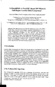
2. PRINCIPLES Real-life images such as natural images, medical images, military images etc. that are used on a day-to-day basis are found to comply largely with the following two observations: 1. Not all grayscale intensity levels are used in the image. 2. There are a significant amount of run-lengths of zeros (or some compressible pattern) in the image. The first observation implies that for most images, even if the permissible dynamic range for the intensity values is [N , M ] (M − N + 1 grayscale intensity values), not all these values actually appear in the original image. The dynamic range used in reality is typically [n, m] where n > N and m < M . For an 8-bit image such as Lena (Fig.1), N = 0, M = 255, whereas n = 25 & m = 245. This means that the grayscale intensity values 0 to 24 and 246 to 255 never occur in this particular image. Similarly, for the 16-bit CT image shown in Fig.1, [N , M ] = [0, 65535] and [n, m] = [0, 2360] which implies that the grayscale values [2361, 65535] never occur in the image. The second observation is due to the fact that images are redundant5 (statistically) which is indicated by the entropy of the image. The first-order entropy of the Lena image is 7.4455 bits/pixel and that of the CT image is 8.0495 bits/pixel. This redundancy is what enables compression algorithms to compress the image. The two observations mentioned above, though simple are yet very powerful and form the basic working principles to be exploited by the methods described in this paper. From the above observations, we infer that there are some gray levels which apriori is known not to occur in the image by all clients (this information is transmitted in the header, in case of DICOM images, it is sent in one of the fields in the header). The other inference is that we could in principle exploit the redundancy in the image to transmit the embedded data. Instead of removing the redundancy, which is what (lossless) compression methods6 do, we could replace the redundancy with an equivalent amount of information of the embedded data. For simplicity purposes, we consider only those images which satisfy both the observations. It is interesting to note that this is usually true for most medical and natural images. It should also be noted that most medical data-sets are three dimensional and this provides us with a high information embedding capacity.
3. DATA EMBEDDING AND EXTRACTION PROCEDURE The method of embedding data into a host image which satisfies the two observations and the parser (decoder) for extracting the host data and recovering the embedded data is described here. We do not discuss security issues in this paper.
SPIE USE, V. 1 5370-219 (p.2 of 8) / Color: No / Format: A4/ AF: A4 / Date: 2004-01-19 06:38:07
Please verify that (1) all pages are present, (2) all figures are acceptable, (3) all fonts and special characters are correct, and (4) all text and figures fit within the margin lines shown on this review document. Return to your MySPIE ToDo list and approve or disapprove this submission. 6000
50 5000
100 150
4000
Count
200 250
3000
300 2000
350 400
1000
450 0
500 50
100
150
200
250
300
350
400
450
500
0
50
100 150 Grayscale intensities
200
250
4
6
x 10
50 100
5
150 4
200 Count
250
3
300 2
350 400
1
450 0
500 50
100
150
200
250
300
350
400
450
500
0
500
1000 1500 Grayscale intensities
2000
2500
Figure 1. (a) Top left: The 8-bit Lena image. (b) Top right: Histogram of grayscale intensities. N = 0, M = 255, n = 24, m = 245. (c) Bottom left: A 16-bit CT image. (d) Bottom right: Histogram of grayscale intensities. N = 0, M = 65535, n = 0, m = 2360.
Let [N , M ] be the permissible dynamic range and [n, m] be the actual dynamic range used in the image. Let R1 , R2 , · · ·, RK be the values of the data to be embedded taking values from the alphabet [Q, P ]. These could be ASCII values (Q = 0, P = 255) if one wished to embed text or these could be the co-ordinates of the contour of a Region of Interest (ROI) mask (eg: Q = 0, P = 511).
3.1. Data embedding procedure: 1. Identify all run-lengths of zeros with length L > 1 in the original image (host). 2. For each such run-length of zeros of length L, change the leading zero (the first zero encountered in the block of L zeros, assuming a raster scan for the image) to the value M − L + 1. 3. Change the next L − 1 zeros to the values R1 − Q + m + 1, R2 − Q + m + 1, · · ·, RL−1 − Q + m + 1. 4. Repeat steps 2 and 3 till either all the payload or the run-lengths or zeros in the host image are exhausted. We shall assume that all the values of the payload R1 −Q+m+1, R2 −Q+m+1, ···, RL−1 −Q+m+1 ≤ M or in other words P − Q + m + 1 ≤ M . This is only for the sake of simplicity of explanation. In actual practice, whenever this was violated, we employed a procedure where we break the payload R i into smaller units. As an example, if Ri − Q + m + 1 is actually a 16-bit value but the difference M − m + 1 is only say 16. We break each Ri − Q + m + 1 into 4 units of length 4-bits each. This way, the maximum value of Ri − Q + m + 1 can be only 15 and is less than M − m + 1 = 16. We can then embed these units in the procedure described.
SPIE USE, V. 1 5370-219 (p.3 of 8) / Color: No / Format: A4/ AF: A4 / Date: 2004-01-19 06:38:07
Host data ZeroD-LDE
No. of pixels
No. of pixels
Please verify that (1) all pages are present, (2) all figures are acceptable, (3) all fonts and special characters are correct, and (4) all text and figures fit within the margin lines shown on this review document. Return to your MySPIE ToDo list and approve or disapprove this submission.
Embedded data
Embedded data Host data
N
n
intensities
m
M
N
n
M
m
intensities
ser
Embedded data
n intensities
N
m
+
No. of pixels
N
Embedded data
M
Client-B
Standard DICOM Viewers (ImageTool, Osiris)
Windowing
m n N n
mM
Client-A
No. of pixels
No. of pixels
r
Pa
Host-data
Host-data N
n
intensities
m
n
intensities
m
M
M
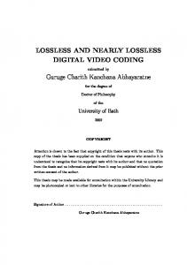
Figure 2. Data extraction procedure for Client-A and Client-B.
The important thing to observe by our method of embedding is that the histograms of the image data and the embedded data do not overlap. As of our knowledge, none of the schemes in literature achieve this and it is precisely this fact which shall help Client-A to view the original host data in a lossless manner by masking off the portion of the histogram which pertains to the embedded data (described in the next section). Another equally important observation is that unlike schemes which compress the data in order to embed and invariably lose the viewing capability of the image, our scheme preserves the existing format of the image. This is very important since this allows DICOM viewers to view the embedded image by only having to do a window-level (as we shall see in the next section). Run-length coding allows us to losslessly compress parts of the data and provides with opportunities in the image to embed data in-place.
3.2. Data extraction procedure: The data extraction procedure is described here. We shall consider two clients namely Client-A and Client-B. We assume that Client-A is not interested in the embedded data but only in the ability to view the original host data in a lossless manner. Further, he has one of the popular DICOM viewers4 (freeware, eg: EzDICOM, OSIRIS, ImageTool etc.). We shall not concern ourselves with the nature of the exact viewer, because any DICOM viewer which has the window-levelling capability would suffice (all DICOM viewers come with this feature). Client-B on the other hand is interested in both, the host image and the embedded information. We shall also describe the parser necessary for Client-B to faithfully (lossless) reproduce the embedded information. Fig.2 illustrates the data extraction and viewing procedure for Client-A and Client-B. For Client-A, it is a trivial matter to view the original image in a lossless fashion by the application of a window-level as shown in the figure. Most DICOM viewers allow this capability. Client-A: 1. Identify all pixels which have a value > m. 2. Set these pixels to a value equal to zero to reconstruct the host image in a lossless fashion.
SPIE USE, V. 1 5370-219 (p.4 of 8) / Color: No / Format: A4/ AF: A4 / Date: 2004-01-19 06:38:07
Please verify that (1) all pages are present, (2) all figures are acceptable, (3) all fonts and special characters are correct, and (4) all text and figures fit within the margin lines shown on this review document. Return to your MySPIE ToDo list and approve or disapprove this submission.
Client-B: 1. Identify all pixels which have a value > m. 2. For each pixel which is thus identified (say x), calculate L = M + 1 − x. This gives the length of the run-length of zeros in that block. 3. Extract the next L − 1 pixel values (these pertain to the values of the embedded data). 4. Add Q − m − 1 to the L − 1 pixels to reconstruct the embedded data as R1 , R2 , · · ·, RL−1 . 5. Set the value of the L pixels starting from x in the original image to zero. This ensures that the original image is reconstructed lossless. 6. Repeat steps 1 to 5 for all block of pixels which are > m.
3.3. Embedding in the negative intensity range We have described the procedure for embedding and extraction of data only on the higher end of the host image histogram. However, the same algorithm can be successfully applied to embed data in run-lengths of zeros as values which are < n (as indicated in Fig.2). An even more interesting application of the idea is to embed data in the negative intensity range for host images which are unsigned. The principle essentially remains the same. We identify run-lengths of zeros and change these to negative values containing information of the embedded data. The advantage of this method is that, all standard DICOM viewers would be automatically tricked in making these values zero (since the DICOM header still reads as unsigned) and no additional window levelling is required for Client-A. Overflow problems for embedding are handled by breaking the message to be embedded into lesser number of bits. The method can also be extended to signed data by embedding data as values which are less than n (we have not constrained n to be positive) but keeping overflow problem into account.
Figure 3. Test images. Top row(left to right): (a) Lena. (b) Barbara. (c) Goldhill. Bottom row(left to right): (d) US. (e) CT.
SPIE USE, V. 1 5370-219 (p.5 of 8) / Color: No / Format: A4/ AF: A4 / Date: 2004-01-19 06:38:07
Please verify that (1) all pages are present, (2) all figures are acceptable, (3) all fonts and special characters are correct, and (4) all text and figures fit within the margin lines shown on this review document. Return to your MySPIE ToDo list and approve or disapprove this submission.
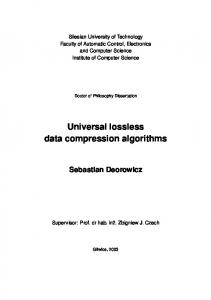
4. RESULTS Two medical images (Fig.3.d and Fig.3.e) were used in our experiment to establish the proof of concept. The first one was a medical Ultrasound image (US, rows=562, columns=768, 8-bit) and the second was a medical CT image (rows=512, columns=512, 16-bit). Fig.4.1(8) and Fig.4.2(9) correspond to the original US(CT) image and the Region of Interest (ROI) mask that needs to be embedded. We have embedded the co-ordinates of the ROI contour in a raster scan fashion. Fig.4.3(10) and Fig.4.4(11) displays the embedded image as viewed by Clients A and B by a standard viewer with a window-level set to mask values greater than the maximum allowable intensity value in the image. It was verified that this viewed embedded image was a bit-by-bit match with the original host data, hence proving that our method is Zero-distortion in the embedded domain. It is also reversble or lossless because both the original and the embedded data were reconstructed losslessly. Fig.4.5(12) is the ROI mask which was decoded by Client B by the parser described in the previous section. We have verified that this was a bit-by-bit match with the embedded mask. Client A is deprived of this information owing to the absence of the parser (decoder). Fig.4.6(13) depicts the image as viewed by Client A without the special window-level setting. He is viewing all the intensities from 0-255(0 to 65536 in case of CT image). Fig.4.7 shows the embedded image as viewed by Client-A without any special window setting (i.e. all 256 values visible) with the embedding restricted to lie within the image. As it can be seen, the data is embedded in the black regions, which have lots of runs of zeros. Table.1 indicates the data-embedding capacities that could be exploited by our method for 3 natural images and 2 medical images (Fig.3). The run-length intensity indicated in the table is the pixel intensity value with the maximum count in the histogram of the host image. The available bit-depth is calculated as log 2 (M − m) bits. The embedding capacity is then computed as log2 (M − m) × Count/8 bytes. This run-length intensity value is the only piece of information that needs to be communicated to the client through header information so that the window-level can be appropriately set. For the US and CT image, the run-length intensity is zero and need not be communicated. The embedding capacities obtained are very high compared to others in literature. For the CT and US image, the embedding capacity is more than 100 kB. This means that with our method, we can embed an 8-bit image of a size which is roughly 115 × 115. Equivalently, this entire paper in PDF format could be embedded in two such images. For a medical image fusion application, we could embed images of one modality into the other. Other applications including embedding biometric information, meta data such as ROI mask, patient information etc. This is by no means an exhaustive evaluation, but only to illustrate the extremely high data-embedding capacities obtained by our method. A more rigorous study and comparison of the performance of our method (with respect to data embedding capacity) with others in literature is outside the purview of this paper. Image
[N, M ]
[n, m]
Lena (512 × 512, 8-bit, unsigned) Barbara (512 × 512, 8-bit, unsigned) Goldhill (512 × 512, 8-bit, unsigned) CT (512 × 512, 16-bit, unsigned) US (562 × 768, 8-bit, unsigned)
[0, 255]
Count
[25, 245]
Run-length intensity 154
2723
Available bit-depth 3.32
Embedding capacity (bytes) 1130
[0, 255]
[12, 246]
159
2217
3.17
878
[0, 255]
[16, 235]
113
2560
4.32
1383
[0, 65535]
[0, 2360]
0
56,874
15.95
1,13,371
[0, 255]
[0, 233]
0
2,38,981
4.46
1,33,231
Table 1. Embedding capacities for a few test images (considering only the higher end of the histogram).
SPIE USE, V. 1 5370-219 (p.6 of 8) / Color: No / Format: A4/ AF: A4 / Date: 2004-01-19 06:38:07
Please verify that (1) all pages are present, (2) all figures are acceptable, (3) all fonts and special characters are correct, and (4) all text and figures fit within the margin lines shown on this review document. Return to your MySPIE ToDo list and approve or disapprove this submission.
Figure 4. (1) Original US image. (2) ROI Mask. (3) Client-A. (4) Client-B. (5) Client-B. (6) Client-A with all gray levels viewed. (7) Client-A with all gray levels viewed (embedding constrained to the image part). (8) Original CT image. (9) ROI Mask. (10) Client-A. (11) Client-B. (12) Client-B. (13) Client-A with all gray levels viewed.
5. CONCLUSIONS A new paradigm in lossless data embedding is presented. ZeroD-LDE claims both lossless reconstruction of host and embedded data and also zero-distortion in the embedded domain. The necessity of a special parser is obviated by this new technique that exploits unused gray levels in the image to embed any kind of data. By lossless compression of run-lengths of zeros, data is embedded in-place. The capacity of the method depends on the redundancy present in the host image and the number of unused gray levels. We have shown that by our method, data can be embedded in unused gray levels beyond the maximum (and minimum) gray value in the image. By the use of a window-level setting available on standard DICOM viewers, the viewer can display the original host image in a zero-distortion manner. The embedding capacities obtained are extremely high, of the order of 100 kB for US and CT images and requires no clinical validation. Further, by embedding data in the negative gray levels, standard viewers can be tricked to automatically mask off all gray values lesser than zero. The method can easily be extended to embed data in unused gray levels lying anywhere in the dynamic range. This would result in a further increase in embedding capacities. Applications that could benefit by this method in medical imaging are embedding segmentation masks, ROI contours, metadata, patient information (encrypted), image fusion etc. The method can also benefit industrial and military applications. Future research steps include comparison with other methods, transform domain embedding and handling encryption and security issues.
SPIE USE, V. 1 5370-219 (p.7 of 8) / Color: No / Format: A4/ AF: A4 / Date: 2004-01-19 06:38:07
Please verify that (1) all pages are present, (2) all figures are acceptable, (3) all fonts and special characters are correct, and (4) all text and figures fit within the margin lines shown on this review document. Return to your MySPIE ToDo list and approve or disapprove this submission.
REFERENCES 1. M. Goljan, and R. Du. Lossless Data Embedding - New Paradigm in Digital Watermarking. Special Issue on Emerging Applications of Multimedia Data Hiding, Vol.2002, No.2, February 2002, pp. 185-196. 2. F. A. P. Petitcolas, R. J. Anderson, and M. G. Kuhn, Information hiding–A survey, Proceedings of the IEEE, vol. 87, pp. 1062-1078, July 1999. 3. M. U. Celik, G. Sharma, A. M. Tekalp, and E. Saber. Reversible Data hiding. Proceedings of the International Conference on Image Processing, Vol. 2, 2002 Page(s): 157 -160. 4. S. C. Horii, DICOM image viewers: a survey, invited paper, Proceedings of SPIE, vol. 5033, pp. 251-259, February 2003. 5. K. Sayood, Introduction to Data Compression, Morgan Kaufmann, February 2000. 6. D. Salomon, Data Compression: The complete reference, Springer Verlag, December 1997.
SPIE USE, V. 1 5370-219 (p.8 of 8) / Color: No / Format: A4/ AF: A4 / Date: 2004-01-19 06:38:07