Mar 11, 2005 - measurement of true mass flow, fluid density and temperature. However, the meter's stability and operability under trace multiphase conditions ...
4th International SEA Hydrocarbon Flow Measurement Workshop 9th-11th March 2005
Three-Phase Flow Measurement Technique Using a Coriolis Flow Meter and a Water Cut Probe Dr. Robbie Lansangan, Robert E. Dutton, P.E., Invensys Foxboro Dr. Michael Tombs, Dr. Manus Henry, Dr. Mihaela Duta, University of Oxford
______________________________________________________________ 1
INTRODUCTION
The ability to measure individual component flow rates of oil, water and free gas in commingled flow without separation presents numerous advantages for the oil and gas industry. This is apparent with the continuous deployment of inline multiphase meters (iMPM) in upstream production operations. The benefits and advantages of multiphase metering in production well testing, compared to separator-based measurement, are well documented [1,2,3]. While the industry has largely accepted the use of iMPM, the purchase price and cost of ownership of these devices are still considered relatively high. Efforts to develop low-cost multiphase meters have generally been based around the use of separation devices such as a compact cyclonic separator coupled with single-phase (conventional) meters. Acceptable performance of compact separation-based multiphase metering (csMPM) relies on the complete separation of the free gas from the liquid phase. While advancement in compact separation technologies has made this achievable, changing well conditions over the life of a field or severe slug flow, for instance, can pose problems. The robustness (and perhaps, large scale acceptability) of csMPM can be realized if accurate measurements can be made under partial separation conditions. The latter requirement, however, places the burden on conventional flow meters to have acceptable performance under what has been called trace or limited multiphase flow regimes. Coriolis mass flow meters are highly regarded for their precision, accuracy and simultaneous measurement of true mass flow, fluid density and temperature. However, the meter’s stability and operability under trace multiphase conditions (less than 5% gas void fraction [GVF]) has generally been considered the Coriolis meter’s Achilles’ heel. Under such conditions it can be difficult for the flowtubes to maintain oscillation, and even at low levels of gas void fraction severe errors may appear on the measurements. While techniques to alleviate the problem have been developed, such as performing background corrections while in trace multiphase conditions, the danger of the meter ceasing to operate at higher gas voids is a looming possibility. These problems with Coriolis measurement have been investigated for over 15 years in the Invensys University Technology Centre at the University of Oxford. A novel all-digital Coriolis mass flow transmitter has been developed which is able to maintain flowtube operation throughout an extended range of two-phase flow [4,5,6]. Invensys Foxboro has made this technology commercially available in the CFT50 product range. This paper presents a new technique in multiphase measurement that utilizes a Coriolis meter with two-phase flow measurement capability and a commercially available water cut probe. The water cut probe presents additional information to provide mathematical closure for the oil, water and free gas resolution. It is envisioned that the Coriolis meter-water cut probe approach can provide the performance requirement that will allow partial separation multiphase metering to be a viable alternative in production well testing. Furthermore, this technique offers the possibility of inline measurement without any separation, for production profiles that fit that upper GVF limit from the limited multiphase standpoint and the flow rates from the meter’s flow capacity, for the Coriolis meter-water cut probe implementation.
1
4th International SEA Hydrocarbon Flow Measurement Workshop 9th-11th March 2005 2
CORIOLIS MASS FLOWMETERS – From Single-Phase to Two-Phase Operation
This section briefly describes the technical developments in the Coriolis meter’s journey from being strictly a single-phase flow meter to being able to measure two-phase flow. It is intended to give a general perspective on a Coriolis meter’s ability to measure two-phase flow in terms of the key breakthrough steps in the development. The technical details can be found in the references. Most, if not all, flow measurement technologies today, have their roots in single-phase flow measurement. These include pressure differential (such as orifice and Venturi) and mechanical meters (turbine and positive displacement). While most industrial flow measurement requirements were satisfied by single-phase flow meters, two-phase flow measurements were occasionally encountered either as a process upset or where phase separation was not an economically and/or technically viable alternative. The need for two-phase flow measurement perhaps began with the invention of the steam engine. Considerably later, a paper published by Murdock [7] in 1962 presented a methodology for measuring two-phase flow with orifices. Today, the Murdock correction factor is widely used in wet steam measurement using orifice plate. Venturi meters are also being used in wet gas flow measurement. These two examples are successful adaptations of single-phase meters for two-phase measurement. This is possible since each meter type continues to operate under two-phase flow albeit giving erroneous readings. Semi-empirical corrections were developed to improve the two-phase flow performance. Coriolis mass flow metering is a well-established technique for single-phase industrial flow measurement. With the well-documented and largely accepted benefits of Coriolis meters in single-phase flow measurement, the adaptation of the technology to two-phase flow was precluded by the meter’s inherent limitation, i.e., the meter simply shuts down after a threshold level of the gas phase is reached. Thus, if a conventional Coriolis meter can be adapted for twophase flow, the first order of the day is to keep the meter operating. Central to this endeavour is maintaining flow tube control during two-phase flow. The research and development on Coriolis meters in the Invensys University Technology Centre at the University of Oxford began with an analysis of a Coriolis meter’s most common failure mode in liquid flow measurement. As it turns out, aerated or two-phase flow topped the list. The following provides an overview of a Coriolis (conventional) meter’s operation and it’s response under two-phase flow. The operation of a Coriolis mass flow meter is dependent upon the proper oscillation of the flowtube. This is controlled by the drive signal(s) generated by the transmitter. The oscillation of the flowtube (as indicated by the sensor signals) is typically sinusoidal and hence characterized in terms of frequency, phase and amplitude. The drive signal is also often sinusoidal, or if not at least a regular waveform (e.g. square wave) for which similar attributes can be defined: the frequency, phase (relative to the sensor signal) and amplitude of the drive signal need to be determined and generated for optimal operation of the flowtube. An obvious and commonly used criterion for flowtube control is that the flowtube should oscillate at its natural frequency of vibration (which will vary with the overall mass of the flowtube and hence the density of the process fluid), at fixed amplitude. Usually measurement algorithms assume constant amplitude of oscillation over the calculation interval, so amplitude stability is relevant for measurement quality. The most common technique for generating a drive signal has been positive feedback, whereby the sensor signal (containing the desired frequency and phase characteristics) is multiplied by a drive gain factor (either by analogue or digital means). The drive gain required to maintain the desired amplitude of oscillation is closely related to the damping on the flowtube, and the two terms are often used interchangeably. Assuming negligible delay in the (analogue) feedback circuit, this ensures phase matching between sensor input and drive output. Positive feedback is relatively easy to implement, but it provides only partial control of the drive waveform, and cannot
2
4th International SEA Hydrocarbon Flow Measurement Workshop 9th-11th March 2005 readily prevent unwanted components in the sensor signal (e.g. other modes of vibration) from being fed back into the drive signal. An alternative approach is drive waveform synthesis, whereby the transmitter calculates a drive waveform digitally, for example a pure sine wave or square wave. This has advantages over positive feedback, including full control over the drive waveform, but the challenge is to match the phase of the sensor signal in real time. Suitable techniques for achieving the latter are described in [8]. The main effect of two-phase flow is a dramatic rise in the flowtube damping, perhaps by two orders of magnitude, which is a significant challenge to the vibration control. Mechanical energy is lost in the interactions between compressible bubbles, fluid and flowtube walls, and the drive energy required to maintain oscillation rises sharply. Not only does the damping rise, but it also varies rapidly, due to the chaotic nature of the interactions. Similarly, the frequency and amplitude of oscillation exhibit much greater variation than for single phase. The consequences for drive output are as follows: • Drive energy saturation. For any intrinsically safe flowtube, there is an absolute limit on the energy supplied to the driver(s). The default amplitude of oscillation may not be sustainable. While many in industry appreciate this limitation, it is widely and wrongly assumed that this is the main reason why flowtubes stall. As shown below, it is perfectly possible to maintain flowtube oscillation through two-phase flow even with an artificially low limit on (say) drive current. By far the most common cause of flowtube stalling is drive gain saturation. • Drive gain saturation. Some positive feedback drives cannot exceed a maximum drive gain limit e.g. due to amplifier saturation. This means there is a maximum multiplier between the sensor amplitude in and the drive signal out. Suppose this limit is reached, and the flowtube damping rises again due to yet more gas in the two-phase flow mix. A further rise in drive current to compensate for the increased damping is not possible, due to drive saturation. As a consequence, the sensor amplitude starts to reduce, but this in turn leads, again because of drive saturation, to a drop in the drive signal output; this in turn leads to a further drop in the amplitude of oscillation; the end result is a catastrophic collapse in oscillation amplitude. • Poor tracking. The rapid changes in damping, amplitude, frequency and phase on the sensor signal require fast and accurate tracking by the transmitter in order to generate an appropriate drive signal. If the drive control update rate is simply too slow, or there is too much dead-time [4], the flowtube may stall due to inattention. A second, possibly worse, alternative, is where oscillation is maintained, but inaccurate tracking leads to phase shift between input and output leading to forced oscillation, and hence wayward frequency of oscillation and poor repeatability. In the high damping conditions of two-phase flow, this may be difficult to detect and correct. Two-phase flow provides different challenges to both of the main drive techniques. With positive feedback, the quality of control is limited, as the drive gain is selected based upon previous amplitude information while the drive signal itself is proportional to the sensor signal, which is varying rapidly. Conversely with synthesis techniques, the problems of tracking phase to ensure natural vibration becomes more difficult. Over the last decade the Sensor Validation Research Group at Oxford has developed a new Coriolis meter transmitter to provide improved measurement performance and robustness [4]. Several features provide improved flowtube control in the face of two-phase flow, including: • Measurement and control updates every half drive cycle (typically every 6ms) • Rapid dynamic response [9] • Synthesis of a pure sine wave with the required amplitude, frequency and phase characteristics, providing a highly adaptable and precise drive signal. • A non-linear amplitude control algorithm providing stable oscillation [6].
3
4th International SEA Hydrocarbon Flow Measurement Workshop 9th-11th March 2005 • Selection of a sustainable set point for the amplitude of oscillation during two-phase flow. • The ability to generate counter-phase signals or so-called negative gain (see below) Figure 1 demonstrates the precision of the flowtube control system via a sequence of set point changes over 3 orders of magnitude. The default amplitude is 0.3V. This is reduced to 30mV, 3mV, and finally 0.3mV, before these steps are reversed, all within 45s. Note that 0.3V corresponds to a physical oscillation of 0.6 mm. The graph also shows the drive current requirements during these steps, which reduces linearly with amplitude. Detailed description of flowtube oscillation control during two-phase flow can be found in references [4,5,8]. The drive gain is defined as the ratio of the drive current to the amplitude of oscillation. Its mean value is approximately constant when the amplitude is steady. During set-point changes it exhibits large swings. The control algorithm generates negative gain values when it is desirable to reduce the amplitude of oscillation rapidly. The transmitter does this by generating drive signals that are 180 degrees out of phase with the sensor signals, thus opposing drive motion. This is useful not only for effecting set-point changes, but also for maintaining flowtube stability at low amplitudes (e.g. t=15-25s) and with high damping (e.g. two-phase flow).
Figure 1. Amplitude Control Through Setpoint Changes
4
4th International SEA Hydrocarbon Flow Measurement Workshop 9th-11th March 2005 The robust control of flowtube oscillation of a Coriolis meter is the first step towards being able to use the device under two-phase flow, enabling the meter to operate (and not shut down) during the flow event. In the case of the orifice and Venturi meters cited earlier, the raw measurement exhibited large errors during two-phase measurement, requiring the development of semiempirical corrections to improve the performance. The “improved” Coriolis meter, i.e., one that continues to operate in two-phase flow, alas, also exhibits large measurement errors in both the mass flow and density of the bulk mixture. Theoretical work to improve the Coriolis meter’s performance in two-phase flow has been addressed by several investigators. Grumski and Bajura [10] first proposed the so-called “bubble” theory in 1984. Hemp and Sultan [11] further detailed the problem by attempting to quantify the mass flow and density measurement errors in terms of the gas void fraction. In this theory, a bubble of gas is surrounded by a continuous liquid medium. When the liquid/gas mixture is accelerated, such as in the vibrating tube of a Coriolis meter, then additional bubble motion is generated which is superimposed within the fluid moving fluid relative to a fixed frame of reference. This phenomenon causes a decrease in the observed inertia for the system as a whole. Defining the gas void fraction α as the proportion of gas volume within the total fluid volume (gas plus liquid), the bubble theory predicts that the mass flow measurement will drop by a proportion R, given by
R=
2α 1−α
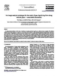
Applied to a Coriolis meter, the model predicts that the observed mass flow will always be less than the true mass flow by the factor R. The bubble theory also predicts that the observed density will be less than the true bulk density by a factor of 2α. Test results with air-water system conducted at the Invensys University Technology Centre at Oxford University showed that the measurement errors roughly correlated with the bubble model. For example, Figure 2 shows the observed mass flow and density errors for air-water system with flow rates ranging from 0.4 to 4.0 kg/s and gas void of up to 80%, using a 1 inch flowtube in horizontal flow direction. The solid line corresponds to the bubble theory prediction. Several observations are noteworthy. The errors in the observed mass flow and density, in general, are negative and appear to have a smooth trend as gas void increases. Both measurements also show a strong dependence on the intrinsic mass flow rate, a phenomenon that is not predicted by the bubble model. In general, as the two-phase mass flow rate through the meter increases, the observed mass flow error decreases while the density error increases. Furthermore, the observed measurement errors appear to be a function of flow tube size, flow tube design and flow orientation. These general trends have been observed to hold over the range of meter size and flow orientation tested with air-water. Another key observation common to the entire body of data for air-water systems is that for a given set of conditions, the results are highly repeatable. The repeatability of the observed mass flow and density measurements has made possible the development of “correction” algorithms (much like the Murdoch correction factor for orifice plates), which have been made available through the Foxboro CFT50 product line. Figure 4 shows the residual mass flow and density error after a correction model, based on the data in Figure 3, was applied online in independent experiments. The density correction is particularly accurate with residual errors generally within ±1% for gas voids up to 70%. The mass flow residual error is well within ±2% for the same data set. The Coriolis meter with two-phase flow measurement capability, as described above, forms the basis for the multiphase measurement technique presented in the following section.
5
4th International SEA Hydrocarbon Flow Measurement Workshop 9th-11th March 2005
Oxford, Water, Horizontal, 1.0" flow range: 0.40kg/s − 4.00kg/s
DENSITY ERROR (%)
0 −10 −20 −30 −40 0
10
20
30
0
10
20
30
40 50 VOID FRACTION (%)
60
70
80
60
70
80
MASSFLOW ERROR (%)
10 0 −10 −20 −30 −40 −50 −60 −70
40
50
Figure 2. Observed Mass Flow and Density Error with two-Phase Flow
Figure 3. Corrected Mass Flow and Density Residual Error
6
4th International SEA Hydrocarbon Flow Measurement Workshop 9th-11th March 2005 3
THREE-PHASE MEASUREMENT WITH CORIOLIS METER AND WATER CUT PROBE
The air-water system described previously, as well as most industrial two-phase flow applications, involves two components. The issue of continuous measurement under two-phase flow and the observed measurement corrections for a Coriolis meter notwithstanding, the resolution of the free gas and liquid flow rates requires the knowledge of two pieces of information. In the case of a Coriolis meter, the mass flow and density measurements provide a sufficient set of information for mathematical closure. This, in fact, is an additional benefit of a Coriolis meter in that no additional device is needed for two-phase flow measurement. The device not only measures the two-phase mass flow and density but can also output the gas and liquid component rates. Note, however, that in the current implementation knowledge of the pure liquid and gas densities are required to correct for the gas-induced mass flow and density errors. In the case of oil, water and free gas in commingled flow, the immiscibility of the oil and water phases results in a three-phase flow condition. While the Coriolis meter in this case treats the immiscible oil-water phases as one liquid phase, the resolution of the oil, water and free gas flow presents a set of three (3) unknowns. Thus, a third piece of information is needed in addition to the two provided by the mass flow meter in order to achieve mathematical closure. In this implementation, a water cut probe provides the additional data. Water cut probes have been used in the oil & gas industry where gas-free oil and water mixtures are measured, for example, at the emulsion leg of a separator or during oil custody transfer operations. The water cut is reported as the proportion of water by volume within the total liquid volume (oil + water). This definition appears to hold regardless of the measurement principle behind a particular water cut probe. In the Coriolis meter-water cut probe implementation, both devices are subject to the same multiphase flowing conditions, assuming the devices are in immediate proximity and properly sized to minimize pressure drop. Figure 4 shows a schematic of the test section used in this study. Multiphase flow enters the static mixer-sampler section located upstream of the water cut probe. A 90-degree bend takes the flow upward into the Coriolis meter. In principle, the correction technique is straightforward: given knowledge of the oil, water and gas densities, the water-cut meter indicates the mixed fluid density, and so the two-phase correction can be applied. In practice, the water cut meter itself is subject to errors induced by the presence of free gas, and so a model of these errors is required. The specific response may vary with the underlying measurement principle for different water cut probes. Implementation of a correction technique for three-phase flow, using a Coriolis meter and water cut probe, is described in the next section.
4
THREE-PHASE TRIAL RESULTS
Three-phase trials were conducted at the Southwest Research Institute’s Multiphase Flow Facility, located in San Antonio, Texas. The fluids used were crude oil with a 35° API gravity, simulated brine with 2% by weight NaCl and nitrogen. The tests were conducted at a pressure of approximately 150 psig and temperature of 100° F. In order to develop a three-phase solution, the observed (raw) response of the Coriolis meter and the water cut probe must be modelled and incorporated into a calculation scheme to resolve the component oil, water and free gas phase flow rates. In practice this can be simplified into calculating the corrected bulk mass flow, bulk density and water cut, from which the flow rates of the three components can be calculated. Figure 5 shows gas-induced error resulting from the raw mass flow and density measurements of the Coriolis meter.
7
4th International SEA Hydrocarbon Flow Measurement Workshop 9th-11th March 2005
Foxboro Coriolis
Static MixerSampler
Flow
Water Cut Probe
Pressure Transmitter
Figure 4. Test Section Schematic Diagram
SWRI, Oil, Vertical, 3" , Test00to50wc flow range: 3000bpd − 8000bpd watercut 00%, 4000bpd watercut 00%, 6000bpd watercut 06%, 3000bpd watercut 06%, 4000bpd watercut 06%, 6000bpd watercut 06%, 8000bpd watercut 13%, 3000bpd watercut 13%, 6000bpd watercut 25%, 3000bpd watercut 25%, 7000bpd watercut 35%, 3000bpd watercut 35%, 7000bpd watercut 50%, 3000bpd watercut 50%, 5000bpd watercut 50%, 7000bpd watercut 50%, 8000bpd
True GVF (%)
Figure 5. Raw Mass Flow and Density Gas-Induced Errors for the Coriolis Meter It can be seen that the mass flow and density errors vary primarily with flow rate and GVF. It is evident, however, that there is variation with water-cut (due to changing viscosity and other fluid
8
4th International SEA Hydrocarbon Flow Measurement Workshop 9th-11th March 2005 properties). This necessitates the use of so-called three-dimensional error models for density and mass flow, which include variations with water cut, as discussed below. Figure 6 shows the observed response of the water cut probe used in these trials. For this particular device, the presence of free gas reduces the observed water cut compared to the true value (for the gas-free oil-water mixture), decreasing monotonically as gas void increases. The response is also found to be a function of the total mass rate and the intrinsic water cut of the liquid phase, amongst other factors. For a given GVF level, the observed water cut generally decreases as total mass rate and intrinsic water cut increases. Regardless of the complexity (or simplicity) of the water cut response surface, what is important is repeatability and the knowledge of how the response may be affected by other parameters such as fluid properties and flow regime. In this regard, further trials are planned to test the implementation at a different flow lab using different fluids.
Figure 6. Raw Water Cut Gas-Induced Error As discussed in [12], one technique for successful modelling of two-phase effects is the use of neural nets. Experimental data is collected sufficient to cover the two-phase region of interest. The behaviour of a range of parameters, including the raw mass flow and density values, all of which can be observed within the flow meter itself, are combined in a neural net to predict mass flow and density errors. Note that the process of building the model (which is computationally demanding) is normally carried out off-line. However, once the model is completed, its on-line use for the purposes of mass flow and density correction has a relatively low computational burden and is readily implemented in a modern digital Coriolis transmitter.
9
4th International SEA Hydrocarbon Flow Measurement Workshop 9th-11th March 2005 In the case of three-phase flow, there are a number of additional complexities. The essential process is the same: neural nets are used to build models based upon suitably chosen experimental data. However, two types of neural net are required, one to model the Coriolis errors as previously, and the second to model the water cut errors. In each case, variations with water cut must be accommodated both within the experimental program and the structure of the neural nets. As illustrated in Figure 7, there are further complexities in the interaction between these two error models. It is desirable for these models to be orthogonal, so that, for example, the use of different water cut probe is possible simply by exchanging models. In order to achieve this orthogonality, it is useful to design the two networks as follows. The water cut model uses the “true” mass flow and density, along with the apparent (i.e. erroneous) water cut, along with other internal parameters, to generate a corrected, “true” water cut. Similarly, the Coriolis error model uses the observed density and mass flow measurements, together with the “true” water cut and other internal parameters to generate corrected, “true” mass flow and density values. A number of implementation issues arise with this approach, as there is a need for initial estimates followed by iteration to convergence between the two error models. Experience suggests that convergence is achievable in order to arrive at a best estimate of the true mass flow, density and water cut values. From these the mass or volumetric flows of each of the three components can be derived.
Apparent Water Cut
Apparent Mass
Water cut error model
Coriolis error model (3D)
Apparent Density
True Water Cut
True Mass Flow True Density
Figure 7. Three-Phase Correction Scheme Figure 8 shows the residual errors for the bulk mixture mass flow, density and water cut measurements, after the neural-net based modelling has been applied, based on the data sets shown in figures 5 and 6. The bulk mass flow errors are mostly kept within ±2% of reading, the bulk density errors are mostly within ±1% of reading, and the water cut errors are mostly within ±2%. These results are significant, given the complexity of the bulk mass flow and density and the liquid phase water cut response surfaces. Figure 9 illustrates how these results are mapped into the corresponding volumetric flow errors for the oil, water and gas streams. Note that for both the gas and water volumes, low absolute volumetric flow (for low water cuts, and low GVF) leads to large percentage errors as a proportion of the reading, while the oil flow rate the errors remain mostly within ±5% band, for water cut of up to 50%. Conversely, it is anticipated that the oil phase flow errors will increase as the water cut increases. Further trials are planned to cover the full water cut range.
10
4th International SEA Hydrocarbon Flow Measurement Workshop 9th-11th March 2005
Figure 8. Residual Errors for Mixture Density, Mass Flow and Water Cut
11
4th International SEA Hydrocarbon Flow Measurement Workshop 9th-11th March 2005
Figure 9. Residual Errors for Water, Oil and Gas Flow Rates
5
CONCLUSIONS
This paper has discussed the issues related to two-phase and three-phase flow measurement based on the use of digital Coriolis mass flow metering. First, it has been demonstrated that the digital Coriolis meter can operate under a variety of fluid systems including two-phase air-water and three-phase oil-water-gas systems. While the Coriolis meter used in this study has been extensively tested and characterised in terms of the correction models for air-water systems, it has been shown that such correction models do not apply for oil-water-gas mixtures. The need for additional information for mathematical closure in three-phase flow notwithstanding, it has been found that the gas-induced error surfaces generated from the raw mass flow and density measurements for oil-water-gas systems were very different and more complex than that of airwater mixtures. More important, however, is that multidimensional correction models using neural nets for the Coriolis meter-water cut probe combination have been developed. These coupled models and the solution method devised have been shown to provide residual errors in the ±1-2% for the bulk mass flow, bulk density and water cut. Mapped into the corresponding phase volumetric rates for oil, water and gas, the residual volumetric errors were generally within the ±5% of reading, at least over the range of conditions in this study.
12
4th International SEA Hydrocarbon Flow Measurement Workshop 9th-11th March 2005 The Coriolis meter-water cut probe technique for (limited) multiphase measurement can have a significant impact in production well testing. Compact separation based multiphase metering can truly become a viable alternative. With the simplicity of operation and the lower cost of this type of multiphase meter, it offers yet another avenue that could reduce the capital cost of field development and the operating cost associated with well testing. Second, full separation requirement of the gas phase in conventional test separators can be relaxed. The emulsion leg of the test separator, retrofitted with the Coriolis meter-water cut probe, can now handle gas carry under. This could have significant impact, for instance, on installed test separators in offshore operations where the problem of gas carry under is often encountered as new, higher volume wells are tied back to existing facilities. Third, the Coriolis meter-water cut probe combination can be installed directly at the wellhead, bypassing the need for any separation, at least for wells with GVF of 30% or less. The benefits of dedicated, real-time individual well production measurement can now be realized with a lower cost Coriolis meter-water cut probe alternative to inline multiphase meters.
13
4th International SEA Hydrocarbon Flow Measurement Workshop 9th-11th March 2005 6
REFERENCES
[1]
Warren, P. B. et al.: “Field-Testing a Compact Multiphase Flow Meter- Offshore Saudi Arabia,” paper SPE 81560 presented at the 2003 SPE 13th Middle East Oil Show & Conference, Bahrain, 5-8 April.
[2]
Khoori, A. et al.: “Multiphase Flowmeter and Production Logs Diagnose Well Response in an Onshore Field, Abu Dhabi,” paper SPE 81534 presented at the 2003 SPE 13th Middle East Oil Show & Conference, Bahrain, 5-8 April.
[3]
Frantzen, K.H., Brandt, M. and Olsvik, K.: “Multiphase Meters: Operational Experience in the Asia-Pacific,” paper SPE 80502 presented at the 2003 SPE Asia Pacific Oil and Gas Conference and Exhibition, Jakarta, Indonesia, 15-17 April.
[4]
Henry, M. P. et al.: “A Self-validating Digital Coriolis Mass-flow Meter: An Overview,” Control Engineering Practice. (2000), 8(5), pp 487-506.
[5]
Henry, M.P.: “Coriolis Meter Digital Transmitter Technology: Emerging Themes,” presented at the 2003 IEE seminar on Advanced Coriolis Mass Flow Metering, Oxford University, UK. 8 July.
[6]
Henry, M. P. et al.: “Response of a Coriolis Mass Flow Meter to Step Changes in Flow rate,” Flow Measurement and Instrumentation. (2003) Vol. #14, pp 109-118.
[7]
Murdock, J.W., “Two-Phase Flow Measurements With Orifices,” Transactions of the ASME, Journal of Basic Engineering. (December, 1962) pp. 419-430.
[8]
Henry, M. P. and Zamora, M. E., “Drive Techniques for a Digital Flowmeter”, US Patent Application 20030216874, 2003.
[9]
Henry, M. P., Zamora, M. E., Clark, C, Cheeswright R., and Mattar, W. “The dynamic response of Coriolis mass flow meters: theory and applications”, ISA 2004 Technical Conference, Houston.
[10]
Grumski, J. T. and Bajura, R. A.: “Performance of a Coriolis Type Mass- Flow Meter in the Measuring of Two-Phase (Air/liquid) Mixtures,” ASME Winter Annual Meeting. (1984) Vol. #17, pp 75-83.
[11]
Sultan, G. and Hemp, J.: “Modeling of the Coriolis Mass-Flow Meter,” Journal of Sound and Vibration (1989), 132(3), pp 473-489.
14