users having ultra small aperture terminals. Such services require high .... the thresholds (8~ and ~2), are determined so that the re- quirements for the false ...
Network Access and Synchronization Procedures for a CDMA Satellite Communication System Diakoumis Gerakoulis
Evaggelos Geraniotis, Hsuan-.J ung Su
AT&T Laboratories Florham Park, N.J 07932
University of Maryland
Abstract This paper provides the network access and synchronzzation procedures of an orthogonal CDMA geostationary satellite system for fixed service communications. These procedures include, initial synchronization, access channel acquisition and fine synchronization control. We also describe the system architecture and provide the performance evaluation. The main objective is to provide network wide synchronization of all uplink orthogonal ~DMA transmisszons. This is achieved in steps; first by providing coarse synchronization using the up link random access channel and then fine sync using innovative tracking control mechanisms. The uplink access channel receiver utilize a parallel/serial search method for rapid code acquisition, while the code tracking of the uplink orthogonal CDMA traffic channel is based on a delay feedback early-late gate in which the sych control resides in the receiver. The proposed system is designed to minimize the onboard complexity and satisfy the performance requirements. As shown in the performance section, the requirement that all up link transmissions are synchronized to a reference time within 10% of the chip length can be achieved. In addition, the system analyszs determines the design parameters values which optimize performance.
1
Introduction
Future geostationary satellite systems are expected to offer direct two-way communications between end satellite users having ultra small aperture terminals. Such services require high system capacity, low bit error rates and low signal-to-noise ratio which can be achieved with a Satellite Switched CDXIA (55/CDNIA). proposed in [Ij. The SS/CDMA uses orthogonal CDMA in both uplink and (lOWflhiflk. The orthogonal CDMA can reject the interference between the user Traffic channels and thus m&xirnize the system capacity. However, the use of orthogonal CDNIA in the uplink, requires a network wide synchronization of all satellite transmissions (global synchronization). The accuracy of the synchronization at steady-state and the speed at which synchronization is acquired depends on the propagation environment i.e., the channel condition, the mobility of the end user, the propagation delay, etc. There are several examples in which synchronous CDMA
College Park, MD 20742 (orthogonal or quasi-orhtogonal) attempted for use in the uplink or inbound channel. One such example is presented in reference [2j in which synchronous CDMA is proposed for mobile satellite applications. Other examples, presented in reference [3~and ~ recommend Orthogonal CDNIA for the inbound and outbound links in terrestrial wireless applications. In reference [~1also shown (by simulation) that the required synchronization jitter from a reference time should. not exceed 10% of the chip length for orthogonal CDNIA operation. This requirement can be achieved easily if the CDMA system has relatively narrow band [~1• On the other hand a wideband orthogonal CDMA requires substantial effort in acquiring and maintaining synchronization, especially in mobile environment. The above referenced systems however, only assume that a synchronization subsystem is in place without presenting one. In this paper we provide the procedures and the system design which can achieve synchronization in a geostationary satellite orthogonal CDMA for fixed service communications. As described in [1J, the multibeam satellite common interface provides Signaling control and user Traffic channels within each satellite beam. The control channels are used for the acquisition of the user Traffic channel. The downlink control channels are, the Pilot, Sync and Paging broadcast channels and are defined by PN-code and orthogonal codes. In the uplink there is an asynchronous Acces channel which has an assigned beam PN-code. The Access channel operation is based on a spread-spectrum random access (SSRA) protocol described in the next section. The Traffic channels are defined by the user orthogonal code and the beam orthogonal and/or PN codes. The system evaluation is focused on the performance of the
Access channel code acquisition and the performance of the tracking control loop. The synchronization procedures and the system design are presented in the next section. In section 3 we provide the system performance evaluation.
2
System Description The satellite common interface provides control chan-
nels (Access in the uplink and Pilot. Sync and Paging in the downlink) and Traffic channels. The Traffic channels are based on orthogonal CDNIA and provide direct links between the end subscriber units (SUs) without onboard
0-7803-5538-5/99/$10.00 (c) 1999 IEEE
decoding. The control channel provide the communication links between the satellite and the SUs and are used for both signaling and synchronization purposes. Control channels have an assigned frequency band different from the bands assigned to Traffic channels. The spreading bandwidth of all bands is the same. In describing the synchronization procedures of the systern we first identify the PN and orthogonal codes of each channel that we use in the process. These codes are: The PN code g~(t) defining the downlink pilot signal which has rate R~ and is transmitted continuously in the frequency band of the downlink control channels, (g~(t) is transmitted with given phase offset Ai corresponding to satellite beam i). The uplink Access channel in beam i is identilied by the PN code a~(t), has a chip rate R~ and operates in an assigned frequency band. Traffic channels are defined by the user orthogonal codes Wk (k 1,2, ...). the beam PN-codes g~(t) (i 1,2, ..) and the beam orthogonal codes W~ (i 1. 2, 3, 4). The codes 1’Vj having chip rate —
R~.
4R,.~
1, provide orthogonal isolation between four adjacent beams. Beam PN-code gi and user orthogonal code l.Vk, have rate R~1. All uplink Traffic Channels codes are required to arrive synchronously at the satellite despreaders in order to maintain the orthogonality between users within the beam as well as between beams. That is, the starting time of all orthogonal codes should be aligned upon arriving at the satellite despreader.
2.1 The Synchronization Procedure The process that provides network wide synchronization consist of a number of steps described bellow: 1. Initial Synchronization: Upon Power-On the SU acquires synchronization to the Pilot PN sequence using the serial search acquisition circuit in the Sync and Paging receiver unit (S&PRU). The S&PRU in the flU will then acquires the corresponding Sync channel in the beam. Based on the system information supplied by the Sync channel the SU will receive the orthogonal code VV~ of the Paging channel (in the downlink) and the PN code a~ of the corresponding Access channel (in the uplink). The SU then acquires and monitors the Paging channel. 2. Access Channel Acquisition: The SU will then male an access attempt in the Access channel. The first message transmitted by the SUk~ (SU k in beam i) and received successfully at the ACRU will be used to establish the time delay (phase offset) A7’kt from the reference arrival time (re,). i.e., Ark. — rk~ — r0. This message may arrive at the satellite despreader at any possible phase offset of the sequence a~(t). An array of K parallel Access Channel Dctectiun Circuits (ACDC) arc then used to cover all phase offsets of the code a~ (as described in section 3) in order to acquire and despread the code. Ark, may l)rov~de a resolotuin of 7> (one chip length), T~/2. T~/4 (T,./e is called chip cell, e = 1,2. or 4); That is, &rk~ = £k~T,./4. The value of Ark, will then be sent back to the SU via a Paging channel. 3. Traffic Channel .4cquisition: The SU will use the value
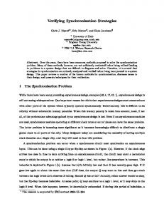
of L\-rk~ to establish Coarse Synchronization to the satellite Reference Arrival Time. This is done by advancing (or delaying) Zki chip cells the starting point of the code from its original position at the successful message transmission. Then, the SU aligns each orthogonal and PN code of the uplink Traffic channel to the code a~ and begins transmission. (The traffic channel orthogonal and PN codes l4’~~, W,., gi in the uplink, and We, W~, gj in the downlink. are supplied to the SI.] by the onboard control unit.) 4. Fine Sync Control: After the SU begin transmitting on the Traffic channel a feedback Tracking Loop will provide fine alignment of the uplink codes with the reference arrival time at the satellite despreaders. This feedback loop extends between the satellite to the ST.] and is described in detail in section 2.2. 5. Sync Retention Control: After steady state has been reached, another Sync control circuit will be used to retain the fine Sync attained in the previous step. This circuit consist of the downlink (Traffic channel) Tracking circuit and uplink SYNC control described in section 2.2. 2.2 The System Design In step 2 of the procedure, the Access channel provides coarse synchronization for the orthogonal uplink Traffic channel. This is an additional function of the Access channel which comes at no extra cost. Its main function is to provide access for call set-up signaling messages. The Access channel operates as an asynchronous random access channel. Its transmissions obey the Spread Spectrum Random Access(SSRA) protocol. According to SSRA, there is one PN code a~(t) for all users in beam i. Each user may begin transmitting a message at any time instant (unslotted channel). Each message consists of a preamble (containing no data) and the message information data field. The transmitted preamble signal will arrive at the receiver at any phase offset of the PN-code. Signals arriving at the receiver more than one chips apart will be distinguished and received. Messages that have (uncorrected) errors due to interference or noise will be retransmitted randomly after the time out interval, while messages that are successfully received will be acknowledged. The Access Channel Receiver Unit (ACRU) consists of a non-coherent detector, an array of parallel Access Channel Detection Circuits (ACDC) and a pool of parallel data decoders. The array of parallel ACDCs, shown in Figure 1, provide a combination of parallel with serial acquisition circuits. Each ACDC searches for synchronization of the message by correlating over a window of vi chips, during the message preamble. The serial search method utilize a typical double dwell algorithm. Given L chips the length of PN co(le a~. and K the number of ACDCs the window size will then be. vi = LIK, (I = w < L). For example if L=1204 chips and IK= 16, then w=64 chips. The correlation process takes l)lace during the message l)reamble. The actual number of parallel ACDCs K is determined by the required length of the preamble interval. In the serial search (double dwell)
0-7803-5538-5/99/$10.00 (c) 1999 IEEE
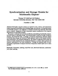
method, the length of the dwell time -y’ and ~Y2as well as the thresholds (8~ and ~2), are determined so that the requirements for the false alarm and detection probabilities are met. Also, the Access channel is assumed to operate at low traffic load in order to offer high probability of successful message transmission with the first attempt. (See performance analysis in section 3.1). The mechanism used in step 4 for fine sync control, is shown in Figure 2. It consists of the on-board SYNC Tracking circuit the downlink feedback path, the SU SYNC control circuit and uplink Traffic channel timing jitter control. The On-board tracking consist of an Early-Late gate that provides the timing jitter Z~. The timing jitter value Z~ will be inserted in a message and sent to the SU via the Paging channel. The SU SYNC Control circuit will then take Z~ as input to make the timing adjustment on the uplink Traffic channel. The Early or Late despreading circhits may rely on the highest chip rate beam code W~, i.e., lVi(t ± ATe) (The other codes gi and P/k have chip length T00 = 4T~). Hence, the design of the proposed tracking loop differs from the typical one since the timing adjustment takes place at the transmitter(SU), not the receiver. This is nessassary in order to allign the transmitted orthogonal code to the reference time (at the satellite) at which all other transmissions have been alligned with. This tracking loop however introduces delays both in the feedback (downlink) as well as in the forward (uplink) path. This delay is equal to the satellite round trip propagation delays which is of about 230 ins. The delay also varies slowly because the satellite has a drift motion of about 2.5 meters/sec. The performance evaluation of this tracking loop have been provided in section 3.2. The last step of the process is required in order to maintain the fine sync achieved in the previous step without making use of the the on-board sync tracking circuit. The onboard tracking circuit will become available (after a steady state is reached) for reuse in another call and thus reduce the onboard hardware. The sync retention control circuitry consists of the downlink Traffic channel tracking circuit and the SYNC control circuit. The feedback signal Z~ of the tracking circuit of the downlink Traffic channel will also feed the input of the SU Sync control circuit. Hence, any change in the satellite propagation delay with respect to the established timing, by Ar~ (resulting from satellite drift motion) will be indicated at the dowolink Traffic channel tracking circuit. The Ar~ timing jitter will then be used (by the SU Sync control circuit) to compensate the uplink trans-
mission by advancing or delaying by
~rp
using the SYNC
control circuit.
3 Performance Evaluation 3.1 The Access Channel Performance Considering the long round trip satellite propagarion delay, the main performance requirement of the Access channel is to provide high probability of success with the first transmission attempt. The probability of a successful mes-
sage transmission depends (a) on the probability of PN code acquisition during the message preamble, (b) on the probability of message collision and (c) on the probability of no bit errors in the message after channel decoding (called Retention probability). (a) The performance analysis (presented in [5J). determines the design parameters for a serial/parallel aquisition circuit which maximizes the probability of acquiring successfully (Pacq) within the preamble interval. These parameters are the minimum preamble interval and the optimum window size w for a given code length of L chips and known interference noise conditions. The probability Pacq refer as the aquisition confidence. is given by Pacq = Pr[Tacq
=T~
=
jTh fThcq(T)dT = FT~,(Th)
(I)
Where, Tacq is the aquisition time for the window size of w chips and Th is the minimum allowed length of the message preamble which satisfies the aquisition confidence. The probability distribution fT~q or the cumulative distribution ~ functions of the acquisition time are derived in
(~I~
(b) Collision of two or more packets will occur if they are
overlapping and have the same PN code phase offset when they arrive at the despreader. This is based on the assumption that the channel is unslotted (continuous time) and a signle PN code has been used for all users in the channel. Also we assume that all packets arrive at the despreader with approximatelly equal power. The probability that packets collide given k0 packets are overlapping at any time instant, is given by P~011(ifk0)
(k0)
(1/L)~(1
—
l/L)koi
for 2 =i =k0 (2)
Where, 1/L is the probability that i packets have exactly the same phase offset of the PN code. The number of all possible phase offsets is assumed to be L, equal to the length of the code (in number of chips). (If the phase offset is less than a chip we assume that collision takes place) The probabilty that k0 packets overlap is given by P(k0)
=
(2t~G)~o e2tpG
(3)
In the above expression t1, is the packet length and C in the total offered traffic load which includes both the newly arrived and retransmitted l)ackets. (Two or more packets will overlap if they arrive in the interval 2t~) The probability of collision then will be
P~0u
=
~
k0>~
ZPcoiKiIA:o)P(ko) 7’ ~—
(4)
(c) The probability of packet retention Pret, is the probability of having no errors in the packet’s information field after FEC. That is, if the packet length is mm bits then
0-7803-5538-5/99/$10.00 (c) 1999 IEEE
Pret = (1 — ~ where P.e is the bit error probability. The probability of successful packet transmission then is given by
Facq(l
In the above equation however we assumed that there packet. If there are ~ parallel data receivers available (as shown in Figure 3) then the probability of not finding an available one is P,.~~(e) = Zk0=eP(k0); Where P(k0) is the probability of having k0 packets overlapping at the reception at a given load G (given in (3)). Then P~, = P.~~[1 — P~~(e)I. Performance Results
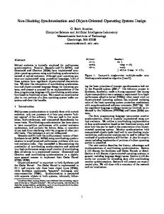
In order to determine the values of Th corresponding to the required acquisition confidence (as in (1)), we first derived the cdf of the acquisition time FT~~q~ (see [sj). In Table 1 we presented the serial/parallel acquisition circuit performance results for code lengths L = 512 and for K = 32, 16 parallel circuits. The false alarm probabilities used are P1~t = 0.01, PF2 = 0.1 and the corresponding penalty Yp is equal to the PN code period L. The mean acquisition time E[Tacq[ varies from 0.3 to 1.4 ms depending on the values of the (E~/Io) (chip energy to interference ratio), L and K. The dwell occumulation values -ytand ‘Y2 are optimized for each case. The required preamble length Th is provided in each case in number of code lengths (xL and in msec assuming the chip rate is R~ = 9.8304 Mc/s. The Th values given in the tables represent the minimum preamble length required to achieve acquisition confidence 95%. As shown, the minimum required preamble length 7’~, varies from 0.73 to 3.65 ms for L = 1024 depending on the channel conditions (E0/10) and the number of parallel ACDCs (K). The packet delays introduced by these preamble lengths are then feasible and acceptable even with delay sensitive traffic. Assuming acquisition confidence Pacq = 0.95 and bit error rate l0—~ (after FEC), we have also evaluated and plotted the probability of successful packet transmission P3~~ versus the offered load (packets/sec) for packet lengths of n = 256 and n = 512 encoded bits (or 128 and 256 information bits assuming FEC rate 1/2) the with ~ = 1,2,3 parallel data receivers (channel decoders). The period of the encoder is 512. The plot is shown in Figure 9. As shown, the ~ is near 0.95 for a wide range of packet load (up to 10 packets/sec), when the packet length is 256 symbols and with 2 or more channel decoders.
3.2 Tracking Control Loop Performance In this section we examine the tracking loop stability and the steady state error. The tracking loop performance is based on the analysis given in references [6! and [7j. The mean and the variance of the discriminator output has been derived for a discrete time model of the loop. The tracking
z—.t lim(1
—
(5)
Pcoii)Pr~
is always a receiver available to decode the data in the
3.1.1
loop has been approximated by a linear model. The steady state timing error (derived in [7[) is be given by
—
.~I)() T~
—
ActF(z) c
(6)
Where F(z) is the loop filter, and c is the normalized doppler shift. The variance of the timing error 2 O~3
Var(r/Tc) is given by (see [7]): =
(Vo ±no)
2w
f~ J~
1
ctF(eiw)eiw&dt)
—
eJw + AaF(eiw)eiw(dt)
2
(7)
The value of Act is usually very small, and as we can see from the above expression the steady state variance increases as ct increases. This implies that given a loop filter, there is an optimal value of ct. We note however that the interference variance V0 is itself a function of the steady state error. A simple form of loop filter is taken for evaluation. F(z)
=
13z—’ 1 ±/
(8)
Computer search shows that ~ can only be in the range of (1,1) 50 the system is stable. We then define a cost function as r.~±2u 3,which means we have more than 95% confidence that the timing error will be smaller than T~±2U~.With the timing error requirement being T~/10, the optimal values of ct and ~3 for which the convergence time is the shortest have then been determined. The complete analysis of the tracking loop is given in [5].
4
Conclusion
In this paper we have presented and evaluated the network synchronization for an orthogonal CDMA satellite system. The objective of providing sychronization of all uplink orthogonal code Traffic channels, as shown, can be achieved with a procedure which involves the uplink random access channel for coarse code acquisition and the use of an innovative feedback tracking control loop for fine synchronization. The Access channel code acquisition scheme is based on a parallel/serial design which is optimized in terms of minimizing the acquisition time and maximizing the acqisition confidence for a given signal-to-noise ratio. Performance analysis indicates that packets may be transmitted successfuly over the Access channel with probability near 0.95 when the traffic load is up to 10 packets/sec and for a given set of system parameters. Performance analysis of the tracking loop has also been performed in order to determine the stability and the optimum loop design. Due to long round trip satellite propagation delay the loop responce has a steady state error which can be corrected by a scaling adjustment. Thus, the requirement of synchronizing each orthogonal code to the reference time within 10% of the chip length can be achieved.
0-7803-5538-5/99/$10.00 (c) 1999 IEEE
References [1] D. Gerakoulis, E. Geraniotis, R. Miller and S. Chassemzadeh. “A Satellite Switched CDMA (SS/CDMA) System Architecture for Fixed Service Communications”. IEEE Communications Magaxine, July 1999.
I.
-
0.9 -
[2] R. De Gaudenzi, F. Giannetti and M. Luise. “Advances in Satellite CDMA Transmission for Mobile and Personal Communications” Proceedings of the IEEE Vol. 84, No. 1, January 1996, pp 18-39.
~
0.55
[3] D.T. Magill, F.D. NataL and G.P. Edwards. “SpreadSpectrum Technology for Commercial Applications” Proceedings of the IEEE Vol. 82, No. 4, April 1994, pp 572-584.
C.de Pe,~d= 024 0.3—
p
0.7.5
[4] JfK. Omura and PT. Yang “Spread-Spectrum 5CDMA for Personal Communication Services” MILCOM’92 pp. 11.3.1-5
-
=oss
—a--— —4-— —4—-— — ~o—
0.7 — ~—
[5] D. Gerakoulis, E. Geraniotis, H-i Su “Network Synchronization of an Orthogonal CDMA Satellite Communication System”. Submitted to the Journal on Se-
— -~—
I
2
Packet Length: 255. 3 Packet Length: 255. 2 Packet Length: 255. 1 Packet Length: 512. 3 Packet Length>512. 2 Packet Length: 51 2. 1 I
I
3
4
5
Ceccder5 Oe~ders D~der O~dei~s Demders D~der 8
Load~a~ket~7s~es1
lected Areas in Communications.
[6] A. J. Viterbi. “CDMA Principles of Spread Spectrum Communications” Addison-Wesley, Massachusetts, 1995.
r~~
.
8
9
10
Figure 3. The Probability of Successful Packet Transmission.
[7] H-J Su, P. Li, E. Geraniotis and D. Gerakoulis. “Code Tracking Loop Performance for an Orthogonal CDMA Uplink SATCOM System”. Conference proceedings, IEEE ISCC’98, Athens, Greece.
K 32 32 32 16 16 16
E~/Io (dB) -10 -12 -14 -10 -12 -14
E[Tacql (ins)
0.3695 0.2537 0.4015 0.3044 0.4811 0.7609
Th (ins) 0.1611 0.5847 0.9251 0.7333 1.1599 1.8334
Th (xL)
7.0937 11.2253 17.7618 14.0784 22.2688 35.1989
Table 1: Acquisition performance for L
=
T R p F
tic P Lc NA KN
512.
N E L
Figure 2. The SYNC and Tracking Feedback Control Loop.
Figure 1. Array of parallel Access Channel Detection Circuits (ACDC).
0-7803-5538-5/99/$10.00 (c) 1999 IEEE