Signal Processor For Digital Audio Applications. Dan Ledger and ... Part Two will
cover example algorithmic building blocks that can be used to implement many ...
a Using The Low-Cost, High Performance ADSP-21065L Digital Signal Processor For Digital Audio Applications Revision 1.0 - 12/4/98
dB +12 0 -12
Left
Right
Left EQ
Right EQ
Pan L
R
L
R
L
R
L
R
L
R
L
R
L
R
L
R
1
2
3
4
5
6
7
8
Mic
High
L
Line Mid
R
Play Back
Bass
CNTR 0 0 3 4
Input Gain
P F R
1
2
3
4
5
6
7
Master Vol.
8
Authors: John Tomarakos Dan Ledger Analog Devices DSP Applications
1
Using The Low Cost, High Performance ADSP-21065L Digital Signal Processor For Digital Audio Applications Dan Ledger and John Tomarakos DSP Applications Group, Analog Devices, Norwood, MA 02062, USA
This document examines desirable DSP features to consider for implementation of real time audio applications, and also offers programming techniques to create DSP algorithms found in today's professional and consumer audio equipment. Part One will begin with a discussion of important audio processor-specific characteristics such as speed, cost, data word length, floating-point vs. fixed-point arithmetic, double-precision vs. single-precision data, I/O capabilities, and dynamic range/SNR capabilities. Comparisions between DSP's and audio decoders that are targeted for consumer/professional audio applications will be shown. Part Two will cover example algorithmic building blocks that can be used to implement many DSP audio algorithms using the ADSP-21065L including: Basic audio signal manipulation, filtering/digital parametric equalization, digital audio effects and sound synthesis techniques.
TABLE OF CONTENTS 0. INTRODUCTION ................................................................................................................................................................4 1. SELECTING AN AUDIO SIGNAL PROCESSOR...........................................................................................................5 1.1 GENERAL PURPOSE DIGITAL SIGNAL PROCESSORS AND DECODERS FOR AUDIO .......................................................5 1.2 PRICE ..........................................................................................................................ERROR! BOOKMARK NOT DEFINED. 1.3 PROCESSOR SPEED ..........................................................................................................................................................5 1.4 ON-CHIP MEMORY ..........................................................................................................................................................7 1.5 I/O CAPABILITIES AND INTERFACES FOR PROCESSING OF AUDIO SAMPLES ..............................................................7 1.5.1 DMA (Direct Memory Access) Controllers..............................................................................................................7 1.5.2 Serial Interface to Audio Converters and other Digital Audio Devices..................................................................7 1.6 DSP NUMERIC DATA FORMATS : FIXED/FLOATING POINT ARITHMETIC....................................................................9 1.6.1 1.6.0 16/24/32-Bit Fixed-Point Arithmetic ............................................................................................................10 1.6.2 Floating-Point Arithmetic ......................................................................................................................................10 1.7 DOUBLE-PRECISION FIXED POINT ARITHMETIC VERSUS SINGLE-PRECISION ARITHMETIC ....................................11 1.8 THE IMPORTANCE OF DYNAMIC RANGE IN DSP-AUDIO PROCESSING ......................................................................11
2
2. USEFUL DSP HARDWARE/SOFTWARE BUILDING BLOCKS FOR AUDIO.......................................................18 2.1 BASIC ARITHMETIC OPERATIONS ................................................................................................................................18 2.2 IMPLEMENTING CONVOLUTION WITH ZERO-OVERHEAD LOOPING, MULTIPLY/ACCUMULATE INSTRUCTIONS (MAC), AND DUAL MEMORY FETCHES .............................................................................................................................18 2.3 HARDWARE CIRCULAR BUFFERING FOR EFFICIENT STORAGE/RETRIEVAL OF AUDIO SAMPLES ...........................19 2.4 ZERO-OVERHEAD LOOPING..........................................................................................................................................20 2.5 BLOCK PROCESSING VS. SAMPLE PROCESSING ...........................................................................................................20 2.6 DELAY-LINES .................................................................................................................................................................20 2.7 SIGNAL GENERATION WITH LOOK-UP TABLES ..........................................................................................................21 3. IMPLEMENTING DSP AUDIO ALGORITHMS ..........................................................................................................23 3.1 BASIC AUDIO SIGNAL MANIPULATION .........................................................................................................................23 3.1.1 Volume Control ......................................................................................................................................................24 3.1.2 Mixing Multiple Audio Signal Channels...............................................................................................................24 3.1.3 Amplitude Panning of Signals to a Left or Right Stereo Field .............................................................................25 3.2 FILTERING TECHNIQUES AND APPLICATIONS ..............................................................................................................29 3.2.1 The FIR Filter ........................................................................................................................................................29 3.2.2 The IIR Filter .........................................................................................................................................................30 3.2.3 Parametric Filters...................................................................................................................................................31 3.2.4 Graphic Equalizers .................................................................................................................................................33 3.2.5 Comb Filters ...........................................................................................................................................................35 3.2.6 Scaling to Prevent Overflow...................................................................................................................................36 3.3 TIME-DELAY DIGITAL AUDIO EFFECTS .......................................................................................................................37 3.3.1 Digital Delay - (Echo, Single Delay, Multi-tap Delays and ADT) ........................................................................37 3.3.2 Delay Modulation Effects.......................................................................................................................................44 3.3.2.1 Flanger Effect .................................................................................................................................................................... 45 3.3.2.2 Chorus Effect ..................................................................................................................................................................... 48 3.3.2.3 Vibrato................................................................................................................................................................................ 54 3.3.2.4 Pitch Shifter ....................................................................................................................................................................... 54 3.3.2.5 Detune Effect...................................................................................................................................................................... 55
3.3.3 Digital Reverberation Algorithms for Simulation of Large Acoustic Spaces.......................................................55 3.4 AMPLITUDE-BASED AUDIO EFFECTS............................................................................................................................61 3.4.1 Tremolo - Digital Stereo Panning Effect...............................................................................................................61 3.4.2 Signal Level Measurement.....................................................................................................................................62 3.4.3 Dynamics Processing..............................................................................................................................................63 3.4.3.1 Compressors and Limiters ................................................................................................................................................ 63 3.4.3.2 Noise Gate/Downward Expander ..................................................................................................................................... 66 3.4.3.3 Expanders........................................................................................................................................................................... 67
3.5 SOUND SYNTHESIS TECHNIQUES...................................................................................................................................67 3.5.1 Additive Synthesis ...................................................................................................................................................67 3.5.2 FM Synthesis ..........................................................................................................................................................68 3.5.3 Wavetable Synthesis ...............................................................................................................................................68 3.5.4 Sample Playback ....................................................................................................................................................68 3.5.5 Subtractive Synthesis..............................................................................................................................................69 4. CONCLUSION...................................................................................................................................................................69
3
0. INTRODUCTION This document will serve as an introduction for those new to digital signal processing with interests in digital audio. It will first cover important DSP features for use in audio application such as precision, speed, data format and I/O capabilities. Some basic comparative analysis will be shown for DSPs that are targeted for professional and consumer audio applications. Dynamic range requirements for high fidelity audio processing will also be discussed. Finally, there will be some discussion on various programming techniques that can be used for creating DSP algorithms using the ADSP-21065L. Hardware circular buffering, delay lines usage, and wavetable lookups will be presented with tips on how these building blocks can be used in certain algorithms. Implementation of various digital audio algorithms will be demonstrated, with theoretical equations as well as actual coding implementations shown wherever possible. These include basic audio signal manipulation, filtering techniques, waveform synthesis techniques, digital audio effects and more. In general, most audio algorithms fall under one of three classes: Professional, Prosumer, and Consumer Audio. For Professional Audio, the applications are targeted to a specific consumer base that consists of professional musicians, producers, audio engineers and technicians. Prosumer Audio includes many professional applications, but aimed more at lower cost, higher volume equipment sold through local music equipment retailers. Consumer Audio applications target a high volume customer base through consumer electronic retailers. Many basic DSP algorithms are used in all three markets segments, while others are used only in the professional or consumer space. Table 1 shows some examples of the types of products and audio algorithms used in the professional and consumer markets to help demonstrate the differentiation between the two markets. Professional Audio Products • Electronic Music Keyboards • Digital Audio Effects Processors (Reverb, Chorus, Flanging, Vibrato Pitch Shifting, Dyn Ran. Compression….)
• Vocal “Harmonizers” / Formant-Corrected Pitch Shifters • Graphic and Parametric Equalizers • Digital Mixing Consoles • Digital Recording Studios (DAT) / Multichannel Digital Audio Recorders • Speaker Equalization • Room Equalization Consumer Audio Products Karaoke Digital Graphic Equalizers Digital Amplifiers/Speakers Home Theater Systems {Surround-Sound Receivers/Tuners} Digital Versitile Disk (DVD) Players Digital Audio Broadcasting Equip. CD Players and Recorders CD-I Satellite (DBS) Broadcasting Satellite Reciever Systems Digital Camcorders Digital Car Audio Systems (Digital Speakers, Amps, Equalizers Surround-Sound Systems)
---------------------------------------Computer Audio Multimedia Systems
Algorithms Used Wavetable/FM synthesis, Sample Playback, Physical Modeling Delay-Line Modulation/Interpolation, Digital Filtering (Comb, FIR….) STFFT(Phase Vocoder), additive synthesis, frequency-domain interpolation(Lent’s Alg), windowing Digital FIR/IIR filters Filtering, Digital Amplitude Panning, Level Detection, Volume Control Compression techniques: MPEG, ADPCM, AC-3 Filtering Filtering Algorithms Used MPEG, audio effects algorithms Digital Filtering Digital Filtering AC-3, Dolby Prologic, THX DTS, MPEG, Hall/Auditorium Effects AC-3, MPEG... AC-3, MPEG... PCM ADPCM, AC-3, MPEG AC-3, MPEG AC-3, Ex. Circle Surround (RSP Tech.) Digital Filtering...
3D Positioning (HRTFs), ADPCM, MPEG, AC-3 ….
Table 1 : Some Algorithms Used In Professional and Consumer Audio
4
1. SELECTING AN AUDIO SIGNAL PROCESSOR The ADSP-21065L contains the following desirable characteristics to perform real-time DSP computations: •
Fast and Flexible Arithmetic Single-cycle computation for multiplication with accumulation, arbitrary amounts of shifting, and standard arithmetic and logical operations.
•
Extended Dynamic Range for Extended Sum-of Product Calculations Extended sums-of-products, common in DSP algorithms, are supported in multiply/accumulate units. Extended precision of the accumulator provides extra bits for protection against overflow in successive additions to ensure that no loss of data or range occurs.
•
Single-cycle Fetch of Two Operands For Sum-of-Products Calculations In extended sums-of-products calculations, two operations are needed on each cycle to feed the calculation. The DSP should be able to sustain two-operand data throughput, whether the data is stored on-chip or off.
•
Hardware Circular Buffer Support A large class of DSP algorithms, including digital filters, requires circular data buffers. The ADSP-21065L is designed to allow automatic address pointer wraparounds to simplify circular buffer implementation, and thus reducing overhead and improving performance.
•
Efficient Looping and Branching for Repetitive DSP Operations DSP algorithms are repetitive and are most logically expressed as loops. The 21065L's program sequencer allow looping of code with minimal or zero overhead. Also, no overhead penalties for conditional branching instructions.
1.1 General Purpose Digital Signal Processors and Decoders For Audio There are many tradeoffs which must be considered when selecting the ideal DSP for an application. In any cost sensitive, high volume audio application with high fidelity requirements, designers look for a number of desired features at the lowest available cost. Generally, these are often speed, flexibility, data types, precision, and on-chip memory. There are a handful of DSPs and audio decoders on the market today with architectures targeted for the consumer and professional audio like the Analog Devices ADSP-21065L, Crystal Semiconductor CS4923, Motorola DSP563xx family and Zoran ZR385xx family.
1.2 Processor Speed Processor speed generally determines how many operations can be performed within a DSP in a set amount of time. There are two units of measurement that are typically used to describe the speed of a chip: Megahertz and MIPS (millions of instructions per second). The clock speed of the chip is measured in Megahertz (MHz), or millions of cycles per second. This is the rate at which the DSP performs it most basic units of work [5]. Most DSPs perform at least one instruction per clock cycle. The second unit of measurement, MIPS describes exactly what it stands for : millions of instructions per second. It is important, however, to understand how specific DSP manufacturers define an instruction. Some manufacturers will count multiple operations executed in one instruction opcode as more than one machine instruction while other maintain the one instruction opcode equals one instruction.
1.3 On-Chip Memory The ‘on-chip’ memory in a DSP is the memory integrated inside of the DSP which is used to store both program instructions and data. The size of on-chip memory in today’s DSP is increasing due to the changing to meet the memory requirements for evolving DSP algorithms used today. As shown in Section 3, many audio applications generally require large memory buffers. Off-chip memory can add to the system cost and increase PCB real estate, so the trend in recent years has been an increase in 'on-chip' memory integration. In addition, a 'bus bottleneck' can be produced during computationally intensive DSP routines executed off-chip, since it usually takes more than one DSP cycle to execute dual memory fetch instructions. This is because DSP manufacturers will multiplex program and data memory address and data lines together off-chip to save pins on the processor and reduce the package size, thus compromising the performance of Harvard Architecture-based processors.
5
1.4 I/O Capabilities and Interfaces For Processing Of Audio Samples Another important consideration in selecting a DSP is determining if the DSP communication with the outside world is fast and efficient enough to handle a particular application’s requirements. The designer must determine the transfer rate requirements for any given application in order to determine what type of DMA and peripheral interface would be adequate for the design. Many DSPs include a number of on-chip peripherals that can transmit or receive data in various binary formats between the DSP and the outside world. Many devices require a memory-mapped parallel interface or serial interface, so DSP peripheral support plays a crucial role in what types of devices can be used with the selected DSP.
1.4.1 ADSP-21065L DMA (Direct Memory Access) Controller The ADSP-21065L includes a number of peripherals that can transmit or receive data from the outside world and the DSP core. On-chip DMA circuitry handles transfer of data between the DSP and external device. The ADSP-21065L host interface circuitry allows for an easy interfade to an 8, 16 or 32-bit host processor. The ADSP-21065L's zero-overhead DMA controller capable of transferring data between all I/O ports and the DSP core with no processor intervention.
1.4.2 ADSP-21065L Serial Interface to Audio Converters and other Digital Audio Devices The ADSP-21065L has 2 serial ports to allow interface to synchronous devices as well as inter-processor communication. Enhanced modes of operation include multichannel TDM communication as well as support for standard audio protocols such as Philips I2S, Sony CDP, and AC'97 digital audio protocols. Synchronous Serial Ports with Time Division Multiplexing The ADSP-21065L supports a TDM multichannel mode to easily interface to many synchronous serial devices such as Audio Codecs, Audio A/D Converters and Audio D/A Converters. Many codecs can operate in a TDM scheme where control/status information and stereo data are sent in different 'timeslots' in any given serial frame. For example, multichannel mode is often used for interfacing to the Analog Devices AD1847 multichannel SoundPort codec. AC'97 compatible devices such as the Analog Device AD1819A can also be interface to the ADSP-21065L in this mode. For example, the ADSP-21065L EZ-LAB Development board uses the AD1819a, which is a TDM protocol based on the AC-97 1.03 specification. Philips I2S Digital Serial Protocol In consumer and professional audio products of recent years, the analog or digital ‘front-end’ of the DSP uses a digital audio serial protocol known as I2S. Audio interfaces between various ICs in the past was hampered because each manufacturer had dedicated audio interfaces that made it extremely difficult to interface these devices to each other. Standardization of audio interfaces was promoted by Philips with the development of the Inter-IC-Sound (I2S) bus, a serial interface developed for digital audio to enable easy connectivity and ensure successful designs. In short, I2S is a popular 3 wire serial bus standard protocol developed by Philips for transmission of 2 channel (stereo) Pulse Code Modulation digital data, where each audio sample is sent MSB first. I2S signals, shown in Figures 1 and 2, consist of a bit-clock, Left/Right Clock and alternating left and right channel data. This protocol can be compared to synchronous serial ports in TDM mode with 2 timeslots ( or channels) active. This multiplexed protocol requires only 1 data path to send/receive 2 channels of digital audio information.
6
Figure 1 I 2 S Digital Audio Serial Bus Interface Examples
Transmitter
Reciever SCLK LR_Select
DSP Serial Bus Master
SDATA
Audio D/A
Figure 2. Example I2S Timing Diagram for 16-bit Stereo PCM Audio Data SCLK
Left/Right FS Clock
Left Channel Select
Right Channel Select
1 Serial Bit Clock Delay From LRCLK transistion
Transmitter
Reciever
Serial Data
SCLK
Audio A/D
LR_Select
0
15 14 13 12 11 10 9
M S B
8
7
6
5
Left Sample
4
3
2
1
0 15 14 13 12 11 10 9
L M SS BB
8
7
6
5
4
3
2
1
Right Sample
0
L S B
DSP
SDATA Serial Bus Master
Audio data word sizes supported by various audio converter manufacturers range can be either 16, 18, 20, or 24 bits
2
As a result, today many analog and digital audio 'front-end' devices support the I S protocol. Some of these devices include: • • • • • •
Audio A/D and D/A converters PC Multimedia Audio Controllers Digital Audio Transmitters and Receivers that support serial digital audio transmission standards such as AES/EBU, SP/DIF, IEC958, CP-340 and CP-1201. Digital Audio Signal Processors Dedicated Digital Filter Chips Sample Rate Converters
The ADSP-21065L has 4 transmit and I2S serial port support for interfacing to up to 8 commercially available I2S devices Some audio DSPs and decoders also integrate analog and digital audio interfaces on-chip which results in a savings in PCB space, as well as cost savings. Figure 3 below shows two examples for interfacing I2S devices to a DSP. DSPs without I2S support can still interface to these devices with the use of an FPGA. . This allows a designer to take use multiple I2S devices with many commercially available DSPs that support a serial time-division multiplexed scheme but do not have built in support for I2S. The timings between the devices can be resolved so that data can be aligned to a particular time-slot in the DSP TDM frame . Thus, the ADSP-21065L's built-in support for the I2S protocol eliminates the need for the FPGA and result in a simple, glueless interface. Standard DSP synchronous serial ports with a TDM mode can still be interfaced to I2S devices, but additional glue logic via an FPGA will be required to synchronize a sample to a particular DSP timeslot.
7
Figure 3, Example I2S/DSP Interfaces Audio Interface to a DSP Serial Port with I2S Support
Audio Interface Interface to a DSP Serial Port in TDM Mode Bi-Directional Sychronous TDM Serial Interface
I2S Devices
3
A/D Converter
FPGA
I2S Devices
DSP
4
D/A Converter
DSP 3
3
D/A Converter
D/A Converter
3
3
3
3
3
D/A Converter D/A Converter
I2S Serial Interface
3
Digital Audio Transmitter
Digital Audio Receiver
3
3
D/A Converter
3
Digital Audio Transmitter
A/D Converter
Digital Audio Receiver
SPD/IF & AES/EBU Digital Audio Transmitters and Receivers The ADSP-21065L's I2S interface easily allow transmission and reception of audio data using industry standard digital audio serial protocols. These devices act as a 'digital' front-end for the DSP. There are primarily 2 dominant digital protocols used today. One is used for professional audio and the other for consumer audio. AES/EBU (Audio Engineering Society/European Broadcast Union) is a standardized digital audio bit serial communications protocol for transmitting and receiving two channels of digital audio information through a transmission line (balanced or unbalanced XRL microphone cables and audio coax cable with RCA connectors). This format of transmission is used to transmit digital audio data over distances of 100 meters. Data can be transmitted up to 24 bit resolution, along with control, status and sample rate information embedded in frame[37]. AES/EBU is considered to be the standard protocol for professional audio applications. It is a common interface that is used in interfacing different professional mixing and DAT recording devices together. The AES3-1992 Standard can be obtained from the Audio Engineering Society.
Figure 4. 0
AES3 Frame Format
3 4 L
Preamble
S B
27 28 29 30 31 Up to 24 bit Audio Sample Word (16/20/24 Data)
Audio Engineering Society Recommended Practice: AES3-1992: Serial Transmission Format for TwoChannel Linearly Represented Digital Audio Data
M S
V
U
C
P
B
V = Validity U = User Data C = Channel Status P = Parity Bit
SPD/IF (Sony/Philips Digital Interface Format) is based on the AES/EBU standard in operating in 'consumer' mode. The physical medium is an unbalanced RCA cable. The consumer mode carry less control/status information. Typical applications where this interface can be found is in home theater equipment and CD players. Digital Audio Receivers typically receive AES/EBU and SP/DIF information and convert the audio information into the I2S (or parallel) format for the ADSP-21065L, as well as provide status information that is received along with the audio data. Digital Audio Transmitters can take an I2S audio stream from the ADSP-21065L and transmit the audio data along with control information in AES/EBU and SPD/IF formats.
8
1.5 DSP Numeric Data Formats : Fixed/Floating Point Arithmetic Depending on the complexity of the application, the audio system designer must decide on how much computational accuracy and dynamic range will be needed. The most common native data types are explained briefly in this section. 16- and 24-bit fixed-point DSPs are designed to compute integer or fractional arithmetic. 32-bit DSPs like ADI's 2106x SHARC family were traditionally offered as floating point devices, however, this popular family of DSPs can equally perform both floating point arithmetic and integer/fractional arithmetic.
1.5.1 1.6.0 16/24/32-Bit Fixed-Point Arithmetic DSPs that can perform fixed point operations typically use a two’s complement binary notation for representing signals. The representation of the fixed-point format can be signed (twos-complement) or unsigned integer or fractional notation. Most DSP operations are optimized for signed fractional notation. For example, the numeric format in signed fractional notation would correspond to the samples produced from a 5 V A/D converter as shown in figure 4 below. The highest full scale positive fractional number would be 0.999…. while the highest full scale negative number is -1.0. Figure 4
Figure 5 Fractional And Integer Formats
Signed Two’s Complement Representation of Sampled Signals
• Fractional format is 1.15 / 1.23 / 1.31 notation
+5 V
0x7FFF….
S• F F F
F F F F... F F F F
F F F F
radix point
0V
0x0000….
• Integer format is 16.0 / 24.0 / 32.0 notation S I I I
I I I I
I I I I
I I I I •
-5 V
0x8000….
radix point
In the fractional format, the binary point is assumed to be to the to the left of the LSB (sign bit). In the integer format, the binary point is to the right of the LSB (figure 5).
1.5.2 Floating-Point Arithmetic The native floating point capability of the ADSP-21065L has data paths that are 32 bits wide., where 24 bits represent the mantissa and 8 bits represent the exponent. The 24 bit mantissa is used for precision while the exponent is for extending the dynamic range. For 40 bit extended precision, 32 bits are used for the mantissa while 8 bits are used to represent the exponent (figures 6 and 7). Figure 6. IEEE 754 32-Bit Single Precision Floating-Point Format 31
S Sign Bit
30
e7
23
e0
22
1 . f22
8-Bit Exponent
Figure 7. 40-Bit Extended Precision Floating-Point Format
0
39
38
31
f0
S
e7
e0
24-bit Mantissa
Sign Bit
30
0
1 . f 30
8-Bit Exponent
f0 32-bit Mantissa
Binary Point
Binary Point
Hidden Bit
Hidden Bit
A 32-bit floating point number is represented in decimal as: n = m x 2 e -128
It’s binary numeric IEEE format representation is stored on the ADSP-21065L as: n=(-1)S x 2e -128 (1. b0b1b2 ---b23 )
9
It is important to know that the IEEE standard always refers to the mantissa in signed-magnitude format, and not in twoscomplement format. So the extra hidden bit effectively improved the precision to 24 bits and also insures any number ranges from 1 (1.0000….00) to 2 (1.1111….11) since the hidden bit is always assumed to be a 1. Figure 7 shows the 40-bit extended precision format available that is also supported on the ADSP-2106x family of DSPs. With extended precision, the mantissa is extended to 32 bits. In all other respects, it is the same format as the IEEE standard format. 40-bit extended precision binary numeric format representation is stored as: n=(-1) S x 2e -128 (1. b0 b1b2 ---b30 )
Floating Point Arithmetic is traditionally used for applications that have high dynamic range requirements. Typically in the past, trade-offs were considered with price vs performance. Until recently, the higher cost made 32-bit floating point DSPs unreasonable for use in audio. Today, designers can achieve high quality audio using 32-bit fixed or floating point processing with the introduction of the ADSP-21065L, at a cost comparable to 16-bit and 24-bit DSPs.
10
1.6 The Importance Of Dynamic Range In DSP-Audio Processing One of the top considerations when designing an audio system is determining acceptable signal quality for the application. Audio equipment retailers and consumers often use the phrase ‘CD-quality sound’ when referring to high dynamic range audio. Compare sound quality of a CD player to that of an AM radio broadcast. For higher quality CD audio, noise is not audible, especially during quiet passages in music. Lower level signals are heard clearly. But, the AM radio listener can easily hear the low level noise at very audible levels to the point where it can be very distracting. Thus, as an audio signals dynamic ranges, the better distinction one can make for low level audio signals while noise becomes inaudible. The table below shows some comparisons of signal quality for some audio applications, devices and equipment. Figure 9. Audio Device/Application AM Radio Analog Broadcast TV FM Radio Analog Cassette Player Video Camcorder ADI SoundPort Codecs 16 Bit Audio Converters Digital Broadcast TV Mini-Disk Player CD Player 18-bit Audio Converters Digital Audio Tape (DAT) 20-bit Audio Converters 24-bit Audio Converters Analog Microphone
Audio Signal Level (dBu) Relationship Between Dynamic Range, SNR and Headroom
Typical Signal Quality 48 dB 60 dB 70 dB 73 dB 75 dB 80 dB 90 to 95 dB 85 dB 90 dB 92 to 96 dB 104 db 110 dB 110 dB 110 to 120 dB 120 dB
dB
Distortion Region
+25
Peak Level Clipping Point
Headroom
Nominal Electronic Line Level
+4
SNR
Dynamic Range
-65
Noise “Floor” -95
Table 2 : Some Dynamic Range Comparisons Important Audio Definitions [Davis & Jones, 17] (See Figure 9 for graphic representation) • Decibel - Used to describe sound level (sound pressure level) ratio, or power and voltage ratios: dBVolts=20log(Vo/Vi ), dBWatts=10log(Po/Pi), dBSPL=20log(Po/Pi) •
Dynamic Range - The difference between the loudest and quietest representable signal level, or if noise is present, the difference between the loudest (maximum level) signal to the noise floor. Measured in dB. Dynamic Range = (Peak Level) - (Noise Floor) dB • SNR (Signal-To-Noise Ratio, or S/N Ratio) - The difference between the nominal level and the noise floor. Measured in dB. Other authors define this for analog systems as the ratio of the largest representable signal to the noise floor when no signal is present[6], which more closely parallels SNR for a digital system. • Headroom - The difference between nominal line level and peak level where signal clipping occurs. Measured in dB. The larger the headroom, the better the audio system will handle very loud signal peaks before distortion occurs. • Peak Operating Level - The maximum representable signal level at which point clipping of the signal will occur. • Line Level - Nominal operating level ( 0 dB, or more precisely between -10 dB and +4 dB) • Noise Floor - The noise floor for human hearing is the average level of 'just audible' white noise. Analog audio equipment can generate noise from components. With a DSP, noise can be generated from quantization errors. [ One can make an assumption that the headroom + S/N ration of an electrical analog signal equals the dynamic range (although not entirely accurate since signals can still be audible below the noise floor) ]. In undithered DSP-based systems, the SNR definition above is not directly applicable since there is no noise present when there is no signal. In digital terms, dynamic range and SNR (Figure 11) are often both used to describe the ratio of the largest representable signal to the quantization error or noise floor [R. Wilson, 9]. The wordlength for a given processor determines the number of quantization levels that are available. For an n-bit data word would yield 2n quantization levels (some examples shown in Table 4 below). The higher number of bits used to represent a signal will result in a better approximation
11
of the audio signal and a reduction in quantization error (noise), which produces and an increase in the SNR. In theoretical terms, there is an increase in the signal-to-quantization noise or dynamic range by approximately 6 dB for each bit added to the wordlength of an ADC, DAC or DSP. For example, figure 10 demonstrates how 32-bit or 24-bit processing can more accurately represent a given value as compared to 16-bit processing. 24-bit processing can more accurately represent a signal 256 times better than 16-bit processing, while the ADSP-21065L's 32-bit processing can more accurately represent signals 65,536 times better than that for 16-bit processing, and 256 times more accurately than that of a 24-bit processor. n
N Quantization Levels for n-bit data words ( N = 2 levels) 8 2 = 256 16 2 = 65,536 20 2 = 1,048,576 24 2 = 16,777,216 32 2 = 4,294,967,296 64 2 = 18,446,744,073,729,551,616
Table 4: An n-bit data word yields 2n quantization levels Figure 10.
Figure 11.
DSP/Converter SNR and Dynamic Range
Fixed Point DSP Quantization Level Comparisons 1 16-Bit Quantization Step = 256 24-bit DSP Quantization Steps
dB
1 16-Bit Quantization Step = 65,536 32-bit DSP Quantization Steps
Peak Level
+m
1 24-Bit Quantization Step = 256 32-bit DSP Quantization Steps
Headroom Normal Electronic Line Level
+0
1 16-bit Quantization Level
256 24-bit Levels of Quantization
1 16-bit Quantization Level
65,536 32-bit Levels of Quantization
DSP Converter Dynamic ‘System’ SNR Range
N-Bit DSP Dynamic Range & SNR = 6 x N-bits
Established by the A/D and/or D/A converter
-n
Noise “Floor”
DSP Quantization Error = +/- 1/2 LSB
A/D Conversion Error
The maximum representable signal amplitude to the maximum quantization error for of an ideal A/D converter or DSP-based digital system is calculated as:
SNR A / D ( RMS ) ( dB ) = 6 .02n + 1.76 dB
Dynamic Range(dB) = 6.02n + 1.76 dB ≅ 6n
1.76 dB is based on sinusoidal waveform statistics, and would vary for other waveforms [ ], and n represents the data word length of the converter or the processor.
12
Figure 12. Fixed-Point DSP Dynamic Range Comparisons 32-bit DSP 4,294,967,296 Levels of Quantization
24-bit DSP 16,777,216 Levels of Quantization
16-bit DSP 65536 Levels of Quantization
Headroom
0 dB 96 dB Dynamic Range
144 dB Dynamic Range
192 dB Dynamic Range
DSP Noise “Floor”
Fixed Point Dynamic Range per Bit of Resolution = 6dB 16 bit fixed point precision yields 96 dB, 16 x (6 dB per bit) = 96 dB 24 bit fixed point precision yields 144 dB, 24 x (6 dB per bit) = 144 dB 32 bit fixed point precision yields 192 dB, 32 x (6 dB per bit) = 192 dB
Figure 1 above compares the dynamic ranges between commercially available 16, 24 and 32-bit fixed point processors (assuming single-precision arithmetic). As stated earlier, the number of data-word bits used to represent a signal directly affects the SNR and quantization noise introduced during the sample conversions and arithmetic computations. Additional Fixed Point MAC Unit Dynamic Range for DSP Overflow Prevention Many DSPs include additional bits in the MAC unit to prevent overflow in intermediate calculations. Extended sums-ofproducts are common in DSP algorithms are achieved in the MAC unit with single cycle multiply accumulates placed in an efficient loop structure. The extra bits of precision in the accumulator result register provide extended dynamic range for the protection against overflow in successive multiplies and additions, thus ensuring that no loss of data or range occurs. Below is a table comparing the extended dynamic ranges of 16-bit, 24-bit, and 32-bit DSPs. Note that the ADSP-21065L has a much higher extended dynamic range than 16 and 24 bit DSPs when executing fixed point multiplication instructions. N-bit DSP 16-bit DSP 24-bit DSP 32-bit 21056L
N-bit x N-bit Multiply 32-bits
Additional MAC Result Bits 8-bits
Precision in MAC Result Register 40-bits
Additional Dynamic Range Gained 48 dB
Resulting MAC Dynamic Range 240 dB
48-bits
8-bits
56-bits
48-dB
336 dB
64-bits
16-bits
80-bits
96-dB
480 dB
Developing Audio Algorithms Free From Noise Artifacts If a digital system produces processing artifacts which are above the noise floor of the input signal, then these artifacts will be audible under certain circumstances e.g. when an input signal is of low intensity or limited frequency content. Therefore, whatever the dynamic range of a high-quality audio input, be it 16, 20 or 24 bit samples, the digital processing which is performed on it should be designed to prevent processing noise from reaching levels at which it may appear above the noise
13
floor of the input and hence become audible. For a digital filter routine to operate transparently, the resolution of the processing system must be considerably greater than that of the input signal so that any errors introduced by the arithmetic computations are smaller than the precision of the ADC or DAC. In order for the DSP to maintain the SNR established by the A/D converter, all intermediate DSP calculations require the use of higher precision processing [9,15]. The effects of a finite word length that can degrade an audio signal’s SNR can be the result of any of the following: • A/D Conversion Noise Finite precision of an input data word sample will introduce some inaccuracy for the DSP computation as a result of the nonlinearities inherent in the A/D Conversion Process. • Quantization Error of Arithmetic Computations From Truncation and Rounding DSP Algorithms such as Digital Filters will generate results with must be truncated or rounded up. In IIR filters where feedback is implemented, these errors will tend to accumulate. • Computational Overflow Whenever the result of an arithmetic computation is larger than the highest positive or negative full scale value, an overflow will occur and the true result will be lost. • Coefficient Quantization Finite Word Length of a filter coefficient can affect pole/zero placement and affect a digital filters frequency response. The ADSP-21065L enables precise placement of poles/zeros with 32-bit accuracy. • Limit Cycles Occur in IIR filters from truncation and rounding of multiplication results or addition overflow. These often cause periodic oscillations in the output result, even when the input is zero.
"The overall DSP-based audio system dynamic range is only as good as the weakest link" Thus, in a DSP-based audio system, this means that any one of the following sources or devices in the audio signal chain will determine the dynamic range of the overall audio system: • the analog input signal from a microphone or other device • the ADC word size and conversion errors • DSP word length effects: DSP quantization errors from truncation and rounding, and filter coefficient quantization • output DAC • other connecting equipment used to further process the audio signal
Fielder [38] demonstrates the dynamic range requirements for consumer CD audio requires 16-bit conversion/processing while the minimum requirement for professional audio is 20-bits (based on perceptual tests performed on human auditory capabilities). Dynamic range application requirements for high fidelity audio processing can be categorized into two groups: ‘Consumer CD-Quality’ Audio System uses 16-bit conversion with typical dynamic ranges between 85-93 dB ‘Professional-Quality’ Audio System uses 20-24 bit conversion with dynamic Range between 110-122 dB Maintaining 96 dB 16-bit 'CD-Quality' Audio During DSP Algorithm Calculations When processing audio signals, the DSP must keep quantization errors introduced by arithmetic calculations lower than the converter noise floor. Consider a 'CD-quality' audio system. If the DSP is to process audio data from a 16 bit A/D converter (ideal case), a 96 dB SNR must be maintained through the algorithmic process in order to maintain a ‘CD quality’ audio signal (6x16=96dB). Therefore, it is important that all intermediate calculations be performed with higher precision than the 16-bit ADC or DAC resolution. Errors introduced by the arithmetic calculations can be minimized when using higher dataword processing (single or extended double precision) .
14
Figure 13. Fixed-Point DSP Noise Floor with a typical 16-bit ADC/DAC at 92 dB The higher the number of bits, the more flexibility for roundoff and truncation errors as long as errors to not exceed noise floor of the A/D and D/A Converters. 32-bit DSP
24-bit DSP
16-bit DSP +20dB
20 dB Headroom 0 dB
-72dB -76dB
96 dB Dynamic Range
144 dB Dynamic Range
192 dB Dynamic Range
92 dB A/D and D/A SNR
-124dB -172dB
16-bit A/D Converter Noise “Floor”
16 extra ‘footroom’ bits below noise floor gives largest ‘guard-band’ for compute errors
8 extra ‘footroom’ bits below noise floor
As an comparison example, let's take a look at the processing of audio signals from a 16-bit A/D converter that has a dynamic range close to it's theoretical maximum, in this case with a 92 dB dynamic range and SNR (see Figure 13 above). The 16-bit DSP only has 4 dB higher SNR higher than the A/D converter. For moderate to complex audio processing using single precision arithmetic, the 16-bit DSP data path will not be adequate as a result of truncation and round-off errors that can accumulate. As shown in the Figure 15 below, errors produced from the arithmetic computations will be seen by the output D/A converter. The same sample processing algorithm implemented on a higher resolution DSP would ensure these errors are not seen by the D/A converter. The 24-bit DSP has 8 bits below the converter noise floor to allow for errors, while the the ADSP-21065L (32-bit DSP) has 16-bits below the noise floor, allowing for the greatest SNR computation flexibility in developing stable, noise free audio algorithms. Thus, when using a 16-bit converter for ‘CD-quality’ audio, the general recommendation is to use a higher resolution processor (24/32-bit) since additional bits of precision gives the DSP the ability to maintain the 96dB SNR of the audio converters [9,15, 28]. Double precision math can still be used for smaller data word DSPs if software overhead is available, although the real performance of the processor can be compromised. A 16-bit DSP using single precision processing would only suffice for low cost audio applications where processing is not too complex and SNR requirements are around 75 dB (audio cassette quality). Figure 14. 16-bit A/D Samples at 96 dB SNR 16-Bit A/D Sample
ADC Noise Floor
1514 13 12 11 10 9 8 7 6 5 4 3 2 1 0
16-Bit Data Word
Figure 15. 16-bit D/A Output Samples with Finite Length Effects 16-Bit D/A Output Sample 1514 13 12 11 10 9 8 7 6 5 4 3 2 1 0
Data Transfer of a 16-bit Audio Sample to an N-bit DSP for Processing
16-Bit Data Word
1514 13 12 11 10 9 8 7 6 5 4 3 2 1 0
1514 13 12 11 10 9 8 7 6 5 4 3 2 1 0
DAC Noise Floor Data Transfer of N-bit DSP Result with 18 dB of Noise Introduced from truncation and roundoff errors
24-Bit Data Word
24-Bit Data Word
23 22 21 2019 18 17 16 15 14 13 12 1110 9 8 7 6 5 4 3 2 1 0
23 22 21 2019 18 17 16 15 14 13 12 11 10 9 8 7 6 5 4 3 2 1 0
32-Bit Data Word
32-Bit Data Word
31 30 29 28 27 26 25 24 23 22 21 2019 18 17 16 15 14 13 12 11 10 9 8 7 6 5 4 3 2 1 0
31 30 29 28 27 26 25 24 23 22 21 2019 18 17 16 15 14 13 12 11 10 9 8 7 6 5 4 3 2 1 0
To Maintain 16-Bit Precision, Computation Errors Must Remain Below Noise Floor
Computation Errors of the 16-bit DSP Are Higher Than The Noise Floor of the DAC
15
Summary of requirements for maintaining 16-bit accuracy, 96 dB SNR: • All intermediate calculations must be performed using higher precision filter coefficients and higher precision storage of intermediate samples in larger data word computation registers and/or memory to ensure the noise floor of the algorithm/filter is less than the final truncated output result by the D/A converter • At least 24 bits are required if the quality of 16 bits is to be preserved. However, even with 24-bit processing, it has been demonstrated that care would need to be taken to ensure the noise floor of the digital filter algorithm is not greater than the established noise floor of the 16 bit signal, especially for recursive IIR audio filters. [R. Wilson, 9]. • When processing 16/18/20 bit audio data, the use of 32-bit processing is especially useful for complex recursive processing using IIR filters. For example, parametric/graphic equalizer implementations using cascaded 2nd order IIR filters, and comb/allpass filters for audio are more robust using 32-bit math. The ADSP-21065's 32-bit capability reduces the burden from the DSP programmer to ensure that the quantization error from computations does not go above the ADC/DAC noise floor. • The ADSP-21065L's 32-bit processing can give an additional 48 dB 'guard' benefit to ensure 16-bit signal quality is not impaired during multistage recursive filter computations and and multiple algorithmic passes before obtaining the final result for the DAC.
Processing 110-120 dB, 20-/24-bit Professional-Quality Audio When the compact disc was launched in the early 1980s, the digital format of 16-bit words sampled at 44.1 kHz, was chosen for a mixture of technical and commercial reasons. The choice was limited by the quality of available analog-to-digital converters, by the quality and cost of other digital components, and by the density at which digital data could be stored on the medium itself. It was thought that the format would be sufficient to record audio signals with all the fidelity required for the full range of human hearing. However, research has shown that this format is imperfect in some respects. Firstly, the sensitivity of the human ear is such that the dynamic range between the quietest sound detectable and the maximum sound which can be experienced without pain is approximately 120dB. The 16-bit words used for CD allow a maximum dynamic range of 96 dB although with the use of dither this is reduced to about 93 dB. Digital conversion technology has now advanced to the stage where recordings with a dynamic range of 120dB or greater may be made, but compact disc is unable to accurately carry them. While 16-bit, 44.1 kHz PCM digital audio continues to be the standard for high quality audio in most current applications, such as CD, DAT and high-quality PC audio, recent technological developments and improved knowledge of human hearing have created a demand for greater word lengths in the professional audio sector. 18, 20 and even 24 bit analog-to-digital converters are now available which are capable of exceeding the 96dB dynamic range available using 16 bits. Many recording studios now routinely master their recordings using 20-bit recorders, and quickly moving to 24 bits. These technological developments are now making their way into the consumer and so-called “prosumer” audio markets. The most conspicuous incarnation is DVD which is capable of carrying audio with up to 24-bit resolution. New DVD standards are extending the digital formats to 24-bits at sample rates of 96 kHz and 192 kHz formats. Other products include DAT recorders which can sample at 96kHz. Many professional audio studio manufacturers now offer DAT recorders with 24-bit conversion, 96 kHz sampling rage. In fact, three trends can be identified which have influenced the current generation of digital audio formats which are set to replace CD digital audio, and these may be summarized as follows: • • •
Higher resolution - 20 or 24 bits per word Higher sampling frequency - typically 96 kHz More audio channels
With many converter manufacturers introducing 24-bit A/D and D/A converters to meet emerging consumer and professional audio standards, processing of audio signals will require at least 32-bit processing in order to offer sufficient precision to ensure that a filter algorithm's quantization noise artifacts will not exceed the 24-bit input signal.
16
2. USEFUL DSP HARDWARE/SOFTWARE BUILDING BLOCKS FOR AUDIO This section will briefly review common DSP operations, and show how a DSP programmer can take advantage of the ADSP-21065L processor specific characteristics that allow the designer to easily write DSP algorithms. This DSP was designed to allow efficient coding of real-time signal processing operations such as convolution and vector operations while allowing fast, efficient memory accesses.
2.1 Basic Arithmetic Operations DSPs have the ability to perform a large range of mathematical operations. All DSPs must be able to perform simple operations like addition, subtraction, absolute value, multiplication, logical operations (AND, OR,..). The ADSP-2106x family with it's floating-point support can perform more advanced functions like divisions, logarithms, square roots and averages very efficiently. Figure 16 below summarizes some common code building blocks:
Figure 16. Common DSP Building Block Operations Signal Delay x(n)
Multiplication a Signal By A Constant
z -1
x(n - 1)
c x(n)
cx(n)
Multiplication of Two Signals
Addition of Two Signals
x a (n)
xb ( n)
Σ
x a (n ) + x b ( n)
x b ( n)
x a ( n)
x
x a (n)xb (n)
Subtraction of 2 Signals
x a (n) x b ( n)
-
Σ
x a ( n) - xb ( n)
2.2 Implementing Convolution With Zero-Overhead Looping, Multiply/Accumulate Instructions (MAC), and Dual Memory Fetches A common signal processing operation is to perform a running sum on an input and an impulse response to a system. Convolution involves multiplying two sets of discrete data and summing the outputs as seen in the convolution equation below:
y( n ) = Σ x( m )h( n - m ) m
Examining this equation closely shows elements required for implementation. The filter coefficients and input samples need to come from 2 memory arrays. They need to be multiplied together and added to the results of previous iterations. So memory arrays, multipliers, adders, and a loop mechanism are needed for actual implementation. The ADSP-2106x DSPs can fetch two data words from memory(x(n) and h(n-m)), multiply them and accumulating the product (MAC instruction) to a previous results in one instruction cycle. When used in a zero-overhead loop, digital filter implementation becomes extremely optimized since no explicit software decrement, test and jump instructions are required.
17
Multiply / Accumulates (MAC) Many DSP architectures like the SHARC family include a fixed-point MAC in the computational section to allow a multiply and accumulate in 1 instruction cycle. The DSP needs this support in order to multiply an input sample with a filter coefficient, and add the result to the previous accumulator results.
Dual Memory Fetches with a Modified Harvard Architecture DSP architectural features are designed to perform these computations as quickly as possible, usually within 1 instruction cycle. To perform an operation shown above, a DSP architecture should allow: 1 multiplication with an addition to a previous result, fetch a sample from memory and fetch a coefficient within 1 instruction cycle. To perform the complete convolution operation, an efficient loop hardware should be able to efficiently loop through the number of iterations of the MAC & dual memory fetch instruction.
Figure 17.
The Harvard Architecture PM Program & Data Storage
DM Address
Address Data
DSP µProcessor
Data
Data Storage
I/O Devices
Harvard Architecture: • Simultaneous Access of Data and Instruction Variations of Harvard Architecture: • Single-cycle Access of 2 Data Memories and Instruction (can be from Cache) • Gives Three Bus Performance with only 2 Busses
The ADSP-21065L uses a Modified Harvard Architecture (Figure 17 above) further to enable 2 data transfers and 1 instruction (such as a MAC) to be executed in 1 instruction cycle due to the fact that there are 2 separate memory spaces (program and data) and either a cache or separate PM data bus. The ability to also store data in the Program Memory Space allows the DSP to execute an instruction and performing 2 memory moves in any given cycle. On-chip memory storage allows the DSP programmer to place arithmetically intensive filter computations in internally to maintain single cycle dual memory fetches.
2.3 Hardware Circular Buffering For Efficient Storage/Retrieval Of Audio Samples An important feature for repetitive DSP algorithms is the use of circular buffering. A circular buffer is a finite segment of the DSPs memory defined by the programmer that is used to store samples for processing (Figure 18). The ADSP-2106x DSPs have data address generation units that automatically generate and increment pointers [18] for memory accesses. When data is stored/retrieved from a circular buffer in consecutive locations, the address generation units will ensure that the indirect pointer to the buffer will automatically wrap to the beginning memory address after exceeding the buffer’s endpoint (Figure 19). When circular buffering is implemented in hardware, the DSP programmer does not have to be concerned with additional overhead of testing and resetting of the address pointer so that it does not go out of the boundary of the buffer.
18
Figure 18.
Figure 19.
Circular Buffer of Length N
Hardware Circular Buffering Sampled Waveform Stored in the Memory Buffer
0 1 Wraparound to top after last address is accessed
+ Circular Buffer Pointer Position
2 c c c
Pointer To Current Address
N-2
-
N-1 N
Zero
2.4 Zero-Overhead Looping The Control Unit in the DSP microcomputer must provide efficient execution of data as quickly as possible. For digital filter routines, a running sum of MAC operations is typically executed in fast loop structures with what is know as zero overhead, meaning the branching, loop decrementing, and termination test operations are build into the control unit hardware, saving precious DSP cycles without having to include addition loop construct operation in hardware. Once the loop is initialized, there is no software overhead. The example assembly pseudocode below shows how hardware-controlled loops with zero overhead can produce code that is 3 times faster, after the 1 cycle that is required for setting up the DO Loop Instruction. • Software Loop Example: CNT = 10; Loop1:
Mult/Acc AR, X, Y; Decrement CNT; JNE
Loop1;
• Zero Overhead Hardware Loop Example: CNT=10; Do Loop Until Mult_Acc Done: Mult_Acc:
Mult/Acc AR, X, Y;
2.5 Block Processing vs. Sample Processing DSP algorithms usually process signals by either block processing or sample processing [2]. For block processing, data is transferred to a DSP memory buffer and then processed each time the buffer fills with new data. Examples of such algorithms are fast fourier transforms and fast convolution. The processing time requirement is based on the sample rate times the number of locations in the memory buffer. In sample processing algorithms, each input sample is processed on a sample-by-sample basis through the DSP routine as each sample becomes available. Sampled data is usually passed from a peripheral (such as a serial port) and transferred to an internal register or memory location so it is made available for processing. The is the preferred method when implementing real-time digital filters for infinite duration. For infinite duration sequences, once the DSP is initialized, it will forever process data coming in and output a result as long as the DSP system is powered . So for real-time digital IIR/FIR filters and digital audio effects, sample processing will be the method used for most examples to be covered in this paper. As we will see in the next section, some digital filters and audio effects use sample processing techniques with delay-lines.
19
2.6 Delay-Lines The Delay-Line is a basic DSP building block which is can be used to filter a signal or produce time-based effects such as chorusing, flanging, reverberation and echo. The basic design for any time-delay effect is to simply delay an incoming signal and output the result by some fixed or variable length of time (See general delay line structure in Figure 20). The DSP delayline can be implemented by the following technique [17]: Using an ADC, an input analog signal is converted to it’s equivalent binary numeric representation. These discrete samples are then placed in the DSP’s internal (or external) RAM. To move through the delay-line, the DSP uses addressing generation/modification methods to automatically increment (or decrement) an address pointer after each input sample is stored so the other samples are stored in consecutive memory locations. At the same time, previously stored samples are sent to a DAC from another ‘tapped’ address location in the memory buffer. The DAC converts the digital result back to its analog equivalent. Figure 20 below shows the DSP structure of the delay-line:
Figure 20. Delay Line with buffer size D
x(n)
w 0 (n )
z
-D
Delay(sec) = D Buff. Size x TSamp. Rate
w D (n )
Delay ( sec ) =
y(n) x(n - D)
D Buff . Size fSamp . Rate
The delay time of an DSP-processed audio signal is determined by: 1. Delay Line Buffer Size - number of words (address locations) defined for the buffer. 2. Sampling Rate - determined usually by the audio converters. This also corresponds with the rate at which data is received, processed and returned by the DSP (usually within an interrupt service routine). The address in the buffer is incremented every time samples are stored/retrieved. The I/O difference equation is simply:
y(n) = x(n − D) Usually, the sampling rate of the A/D or D/A converter is related to the rate at which the DSP's interrupt service routine is called for data processing. The DSP interrupt rate usually depends on the AD/DA converters since the converters are connected to the DSP’s serial ports or are using a hardware interrupt pin to notify the DSP when data is being transmitted or received. To increase the delay of a signal, either the buffer size must be increased to store more samples, or the sampling rate can be decreased to increase the delay. Tradeoffs must be considered when choosing longer delay times. Sometimes a DSP only has a limited amount of memory available. The higher the bandwidth requirement of the incoming signal, the more memory storage required by the DSP. But, by decreasing the sampling rate, the bandwidth is reduced. In some cases this is not a problem. For example, human voices or stringed instruments have a bandwidth of only up to 6 kHz. In such cases, a smaller sampling rate will not limit the with the frequency range of the instrument.
2.7 Signal Generation With Look-Up Tables Methods of signal generation for wavetable synthesis, delay-line modulation and tremolo effects can be produced by using a periodic lookup of a signal stored in the DSP’s data memory. Wavetable Generators can be used to implement many timedelay modulation effects an amplitude effects such as the chorus, flanger, vibrato, and tremolo. The figure below shows some of the more common signals that can be easily stored in memory for use in audio applications.
20
Figure 21.
Example Wavetable Storage Signals Useful For Audio Algorithms
Sine
Square
Sawtooth
Triangular
Random LFO
Reverse Sawtooth
Exponential Decay
Rectifier
Trapozoidal
Most high level languages such a C/C++ have build in support to generate trigonometric functions. Real-time Embedded System Software Engineers who program DSP algorithms mostly in assembly do not have the flexibility of a high level language when generating signals. Various methods proposed by Crenshaw [8], Orfanidis [2] and Chrysafis [39] can be used for generating sinusoidal/random signals in a DSP. Signal generation can be achieved by: 1. 2. 3.
Making a subroutine call to a Taylor Series function approximation for trigonometric signals, uniform/Gaussian random number generator routine for random white noise generation. Using a table lookup Using hold/linear interpolation operations between consecutive locations in the wavetable to increase the resolution of the stored signal.
The advantage of using a wavetable to generate a signal is that it is simple to generate signal simply by performing a memory read from the buffer, therefore saving DSP cycle overhead. The wavetable can be implemented as a circular buffer so that the signal stored is regenerated over and over. The larger the buffer, the purer the signal that can be generated. With larger internal memory sizes integrated on many DSPs or the use of low cost commodity SDRAM, the option of using a look-up table is more easily achievable than in the past. To save memory storage, the size of the table can be reduced by a factor of 2, and as suggested above, the DSP can interpolate between 2 consecutive values. For example, a wavetable buffer can contain 4000 locations to represent 1 period of a sine wave, and the DSP can interpolate in between every value to produce 8000 elements to construct the signal. This is not a bad approximation for generating a decent sounding tone What is the best way to progress through the table? The general recommendation for accessing data from the table would be to declare the wavetable in the DSP program as a circular buffer instead of as a linear buffer (see some examples in Figure 22 below). This will allow the signal to be replayed over and over without the program having to check to see if the pointer needs to be reset. Two methods can be used to progress through the lookup table: 1.
Sample-Rate Dependent Update: On method for updating a wavetable pointer is sample-rate dependent update, where a new lookup value is generated every time the sample processing algorithm is entered (typically via an interrupt service routine). This synchronization with the sample rate will not introduce possible aliasing artifacts in implementing delay line modulation.
21
2.
DSP Timer Expire Update: Another method, would be to update the value in the table using the DSP’s on chip programmable timer. Every time the timer expires and resets itself, the timer ISR can update the pointer to the wavetable buffer. This method allow movement through a table that is not relative to the converter's sampling rate, allowing for more flexible and precise timing of signal generation or delay-line modulation.
For certain digital audio effects such as flanging/chorusing/pitch shifting, lookup table updates can be easily achieved using the programmable timer as well as via the audio processing ISR. Delay-line modulation value can be easily updated by using the programmable timer or an interrupt counter to process the parameter used to determine how far back in the delay-line buffer the DSP's data addressing unit needs to fetch a previously stored sample. A sine wavetable can be used to implement many time delay modulation effects an amplitude effects such as the chorus, flanger, vibrato, and tremolo. Random Lowfrequency oscillator (LFO) Tables can be used to implement realistic chorus effects [2]. Using a sawtooth wavetable will be useful for shifting the pitch of a signal [16]. We will look at these examples in more detail in subsequent sections. Figure 22.
Many methods exist for generating wavetable data files for inclusion into a DSP program. An easy way is to use a mathematical software packages such a MATLAB to create data files. Signal tables can even be created using Microsoft Excel. C source also exists on the Internet for generating ASCII files with Hex data for creating simple periodic signals.
22
3. IMPLEMENTING DSP AUDIO ALGORITHMS Now that some techniques for creating components of an algorithm have been proposed, let’s examine some basic to moderately complex audio algorithms that are often used in prosumer equipment. Many of the DSP Techniques we will discuss can be used to implement many of the features found in digital mixing consoles and digital recorders. We will provide some example processing routines for various effects/filters that were implemented using a low cost DSP evaluation platform.
Figure 23.
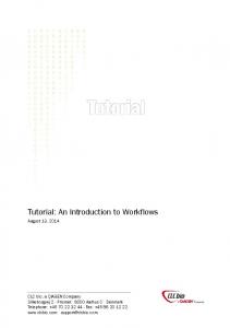
Typical 8 Channel Mixer/Recorder
Left
Right
Left EQ
Right EQ
Pan L
R
L
R
L
R
L
R
L
R
L
R
L
R
L
R
1
2
3
4
5
6
7
8
Mic
High
L
Line
R
Play Back
Mid Bass
CNTR 0 0 3 4
Input Gain
P F R
1
2
3
4
5
6
7
Master Vol.
8
Figure 23 is an example 8 channel mixing console / recorder. Some of the features that are commonly found in mixers and multi-track recorders can be implemented with DSP instructions to perform functions that are often found in mixer equipment as the 8 track recorder shown above: • Channel and Master Gain/Attenuation • Mixing Multiple Channels • Panning multiple signals to a Stereo Field • High, Low and Mid Digital Filters Per Channel • Graphic/Parametric Equalizers • Signal Level Detection • Effects Send/Return Loop for further processing of channels with signal processing equipment Many of these audio filters and effects have been implemented using the ADSP-21065L EZ-LAB development platform, as we will demonstrate in this section with some assembly code examples.. The ability to perform all of the above functions is only constrained by the DSP MIPs. The 21056L's dual multiprocessor system capability can also be used for computationally intensive audio applications. For example, in a digital mixing console application, audio manufacturers typically will use multiple processors to split up DSP tasks or assign different processors to handle a certain number of channels. In the following section, we will model our effects and filter algorithms to cover many of the features that are found in the above digital mixer diagram, and show how easy it is to develop such a system using the ADSP-21065L EZ-LAB.
23
3.1 Basic Audio Signal Manipulation The attractive alternative of choosing to use a DSP is because of the easiness at which a designer has the ability to add, multiply, and attenuate various signals, as well a filtering the signal to produce a more pleasing musical response. In this section we will review some techniques to amplify or attenuate signals, pan signals to the left and right of a stereo field, mixing multiple signals, and pre-scaling inputs to prevent overflow when mixing or filtering signals using fixed point instructions with the ADSP-21065L.
3.1.1 Volume Control One of the simplest operations that can be performed in a DSP on an audio signal is volume gain and attenuation. For fixedpoint math, this operation can be performed by multiplying each incoming sample by a fractional value number between 0x0000…. and 0x7FFF…. or using a shifter to multiply or divide the sample by a power of 2. When increasing the gain of a signal, the programmer must be aware of overflow, underflow, saturation, and quantization noise effects. .VAR
DRY_GAIN_LEFT = 0x6AAAAAAAA;
.VAR
DRY_GAIN_RIGHT = 0x40000000;
/* /* /* /*
Gain Control for left channel */ scale between 0x00000000 and 0x7FFFFFFF */ Gain Control for right channel */ scale between 0x00000000 and 0x7FFFFFFF */
/* modify volume of left channel */ r10 = DM(Left_Channel); r11 = DM(DRY_GAIN_LEFT); r10 = r10 * r11(ssf);
/* get current left input sample */ /* scale between 0x0 and 0x7FFFFFFF */ /* x(n) *(G_left) */
/* modify volume of right channel */ r10 = DM(Right_Channel); r11 = DM(DRY_GAIN_RIGHT); r10 = r10 * r11(ssf);
/* get current right input sample */ /* scale between 0x0 and 0x7FFFFFFF */ /* x(n) *(G_right) */
3.1.2 Mixing Multiple Audio Signal Channels Adding multiple audio signals with a DSP is easy to do. Instead of using op-amp adder circuits, mixing a number of signals together in a DSP is easily accomplished with an ALU’s adder circuit and/or Multiply/Accumulator. First signals are multiplied by a constant number so that the signals do not overflow when added together. The easiest way to ensure signals are equally mixed is by choosing a fractional value equal to the inverse of the number of signals to be added. For example, to mix 5 audio channels together at equal strength, the difference equation (assuming fractional fixed point math) would be: y(n ) =
1 1 1 1 1 x1(n) + x 2(n) + x 3(n) + x 4 (n) + x 5(n) 5 5 5 5 5
The general mixing equation is:
y( n ) =
1 [x ( n ) + x 2 ( n )+ ....... x N ( n)] N 1
Choosing N to equal the number of signals will guarantee that no overflow will occur if all signals were at full scale positive or negative values at a particular value of n. Each signal can also be attenuated with different scaling values to provide individual volume control for each channel which compensates for differences in input signal levels:
y( n ) = c1 x 1 ( n ) + c 2 x 2 ( n )+ ... c N x N ( n ) An example of mixing 5 channels with different volume adjustments can be:
24
1 1 3 1 9 y(n) = x1(n) + x2 (n) + x3 (n) + x4 (n) + x5 (n) 5 10 10 20 20 As in the equal mix equation, the sum of all of the gain coefficients should be less than 1 so no overflow would occur if this equation was implemented using fractional fixed point arithmetic. An example implementation of the above difference equation is shown below.
5-Channel Digital Mixer Example With Custom Volume Control Using The ADSP-21065L #define #define #define #define #define
c1 c2 c3 c4 c5
0x19999999 0x0CCCCCCC 0x26666666 0x06666666 0x39999999
/* /* /* /* /*
c1 c2 c3 c4 c5
= = = = =
0.2, 1.31 fract. format */ 0.1 */ 0.3 */ 0.05 */ 0.45 */
-----------------------------------------------------------------------------------/* Serial Port 0 Receive Interrupt Service Routine */ 5_channel_digital_mixer: /* get input samples from data holders */ r1 = dm(channel_1); {audio r2 = dm(channel_2); {audio r3 = dm(channel_3); {audio r4 = dm(channel_4); {audio r5 = dm(channel_5); {audio
channel channel channel channel channel
1 2 2 2 2
input input input input input
sample} sample} sample} sample} sample}
r6 = c1; mrf = r6 * r1 (ssf);
{mrf = c1*x1}
r7 = c2; mrf = mrf + r7 * r2 (ssf);
{mrf = c1*x1 + c2*x2}
r8 = c3; mrf = mrf + r4 * r2 (ssfr);
{mrf = c1*x1 + c2*x2 + c3*x3}
r9 = c4; mrf = mrf + r4 * r2 (ssfr);
{mrf = c1*x1 + c2*x2 + c3*x3 + c4*x4}
r10 = c5; mrf = mrf + r4 * r2 (ssfr); mrf = sat mrf;
{mrf = y= c1*x1 + c2*x2 + c3*x3 + c4*x4 + c5*x5}
{----------------- write output samples to stereo D/A converter -------------------} r0 = mr1f; dm(left_output) = r0; {left output sample} dm(right_output) = r0; {right output sample}
3.1.3 Amplitude Panning of Signals to a Left or Right Stereo Field In many applications, the DSP may need to process two (or more) channels of incoming data, typically from a stereo A/D converter. Two-channel recording and playback is still the dominant method in consumer and professional audio and can be found in mixers and home audio equipment. V. Pulkki [22] demonstrated placement of a signal in a stereo field (see Figure 4 below) using Vector Base Amplitude Panning. The formulas presented in Pulkki’s paper for a two-dimensional trigonometric and vector panning will be shown for reference.
25
Normally, the stereo signal will contain an exact duplicate of the sampled input signal, although it can be split up to represent two different mono sources. Also, the DSP can also take a mono source and create signals to be sent out to a stereo D/A converter. Typical audio mixing consoles and multichannel recorders will mix down multiple signal channels down to a stereo output field to match the standardized configuration found in many home stereo systems. Figure 25 is a representation of what a typical panning control ‘pot’ looks like on a mixing console or 8-track home recording device, along with some typical pan settings:
Figure 25. Three Typical Pan Control Settings of a Mono Source To A Stereo Output Field
L
R
Full Left Pan
L
R
L
Center Mix
R
Full Right Pan
Many 4/8/12 track analog and digital studios contain a knob to pan an input source entirely to the left or right channel, or played back through both channels at an equal mix (with the pan control centered in the middle). To give the listener a sense of location within the output stereo filed, the DSP can simply perform a multiplication of the algorithmic result on both the left and right channel so that it is perceived from coming from a phantom source.
Figure 27. Pulkki’s Method [26] For Vector Panning of Two-Channel Audio
Figure 26. Panning of Two-Channel Stereophonic Audio Derived by Blumlein, Bauer and Bernfeld [26] x
Virtual Source
Virtual Source
Active Arc
Left Speaker
Right Speaker
Left Speaker
φ
φ0
y
-φ φ0
Active Arc
x
Right Speaker
sin φ g − gR = L sin φ 0 gL + gR
lL
tan φ g − gR = L tan φ 0 gL + gR
p
lR
g Ll L y
0 o < φ 0 < 90 o
g Rl R
p = gLlL + gRlR
y L ( n) = g L x L ( n) y R ( n) = g R x R ( n) To create a panning effect of an audio channel to a particular position in the stereo output field, the programmer can use the Stereophonic Law of Sines, or the Tangent Law equation (Pulkki, Blumlein and Bauer[22].. see Figure 26) where gL and gR are the respective gains of the left and right channels.
26
Stereophonic Law of Sines (proposed by Blumlein and Bauer [22] )
sin φ g -g = L R where 0o < φ 0 < 90o , -φ 0 < φ < φ 0 , and g L , g R ∈[0,1] sin φ 0 g L + g R This is valid if the listener’s head is pointing straight ahead. If the listener turns the head to follow the virtual source, the Tangent Law equation as described by Pulkki [derived by Bernfeld, 26] is modified as:
g − gR tan φ o o = L where 0 < φ 0 < 90 , -φ 0 < φ < φ 0 , and g L , g R ∈[0,1] tan φ 0 g L + g R Assuming fixed point signed fractional arithmetic where signals are represented between 0 (0x0000…) and 0.99999 (0x7FFF…), the DSP programmer will simply multiply each signal by the calculated gain. Using Pulkki's Vector Base Amplitude Panning method as shown in the Figure 27, the position p of the phantom sound source is calculated from the linear combination of both speaker vectors:
p = g Ll L + g R l R The output difference I/O equations for each channel are simply:
y L ( n ) = g L x L ( n ) and y R ( n ) = g R x R ( n ) Vector-Base Amplitude Panning Summary: 1) Left Pan: If the virtual source is panned completely to the left channel, the signal only comes out of the left channel and the right channel is zero. When the gain is 1, then the signal is simply passed through to the output channel. G
L
= 1
G
R
=
0
1) Right Pan: If the virtual source is panned completely to the right channel, the signal only comes out of the right channel and the left channel is zero. When the gain is 1, then the signal is simply passed through to the output channel.
G
R
= 1
G
L
= 0
1) Center Pan: If the phantom source is panned to the center, the gain in both speakers are equal. G
L
=
G
R
4) Arbitrary Virtual Positioning: If the phantom source is between both speakers, the tangent law applies. The resulting stereo mix that is perceived by the listener would be off-scale left/right from the center of both speakers. Some useful design equations [26] are shown below:
gL =
cos φ sin φ 0 + sin φ cos φ 0 2 cos φ 0 sin φ
gR =
cos φ sin φ 0 − sin φ cos φ 0 2 cos φ 0 sin φ
27
sin φ 0 φ = arctan cos φ 0
gL − gR gL + gR
Lookup tables can be used to determine the sine and cosine values quickly to determine the gain factors for the left and right channels if the speaker placement is known and a desired virtual angle is determined. The arctangent approximation can be computed to determine the placement of the virtual source if the speaker placement is known and gain values are arbitrarily selected. Otherwise the programmer can create a panning table with pre-computed left and right gains for a number of panning angles. Two memory storage buffers can be created, one for the left and one for the right channel. To create a virtual pan on-the-fly, the DSP can simply look up the values from memory and perform the multiplication with the output sample prior to the conversion of the sample by the D/A converter. Table 5 below shows left and right channel gains required for the desired panning angle: Table 5. Left/Right Channel Gains for Desired Virtual Panning Placement
φ0 o
45 45o
φ 45
o
gL
gR
1
0
g L− norm g L− norm 1
0
30 o
1366 .
0.366
1
o
1.8737
0.8737
1
45o
10 o
3.3356
2.3356
1
0.2679 0.4663 0.7002
45o
0o
1
1
1
1
45o 45o
− 10 o
−2.3356 −3.3356
0.7002
1
− 20
−0.8737 −1.8737
0.4663
1
1 1
45
45
o
20
o
o
− 30 o
−0.366
−1366 .
0.2679
o
− 45
0
1
0
45
o
After nomalization of the larger gain coefficient to unity, the other channel is a fractional value between 0x0000…. and 0x7FFF…. (unity approximation). From the chart shown above we see that we can use a sine lookup table to calculate the fractional number that can be uses as a gain while the other channel is kept at unity gain (or simply passed from the input through to the desired stereo output channel). Moving through the table periodically to pan left for positive numbers and pan right for negative numbers can create a tremolo/ping-pong effect. At the zero crossing, the phase is reversed as a result of of negative pan values taken from the lookup sine table buffer. Thus, a modified version of the tremolo effect described in section 3.3.3 can be based on the vector based stereo panning concept.
30o Amplitude Panning to a Stereo Output Example
(ADSP-21065L DSP)
{This example assumes speaker placement of 45 degrees, shown in above table} #define Left_Gain 0x7FFFFFFF /* gL = 0.999999, 1.31 fract. format */ #define Right_Gain 0x224A8C15 /* gR = 0.2679 */ -----------------------------------------------------------------------------------/* Serial Port 0 Receive Interrupt Service Routine */ Mono_To_Stereo_Panning_Controller: r1 = dm(audio_data);
{ get audio input sample from codec }
{Note, the left channel can be passed through at unity gain, or multiplied below with a constant close to unity, in this case 0.99999 which is an approximation of 1} r2 = Left_Gain; mrf = r2 * r1 (ssfr);
{mrf = gL * xLeft}
r3 = Right_Gain; mrf = r3 * r1 (ssfr);
{mrf = gR * xRight}
28
{----------------- write output samples to stereo D/A converter -------------------} r0 = mr1f; dm(left_output) = r0; {left output sample} dm(right_output) = r0; {right output sample}
3.2 Filtering Techniques and Applications One of the most common DSP algorithms implemented in audio applications is the digital filter. Digital filters are used to increase and decrease the amplitude of a signal at certain frequencies similar to an equalizer on a stereo. These filters, just like analog filters, are generally categorized in to one of four types : high-pass, low-pass, band-pass and notch and are commonly implemented in one of two forms: the IIR (Infinite Impulse Response) filter and the FIR (Finite Impulse Response) filter. Using these two basic filter types in different configurations, we can create digital equivalents to common analog filter configurations such as parametric equalizers, graphic equalizers, and comb filters. Digital filters work by convolving an impulse response (h[n]) with discrete, contiguous time domain samples (x[n]). The impulse response can be generated with a program like MATLAB and is commonly referred to as a set of filter coefficients. The FIR and IIR examples for the ADSP-21065L include both fixed and floating point equivalent routines.
3.2.1 The FIR Filter The FIR (Finite Impulse Response) filter has an impulse response which is finite in length as implied by its name. The output values (y[n]) are calculated using previous values of x[n] as seen in the figure and difference equation below.
Figure 28. ho y[n]
x[n] wo[n]
Z-1
h1
w1[n]
Z-1
h2
Z-1
hK
w2[n]
wK[n]
∞
y[ n ] = ∑ h[k ]x[n − k ] k =0
Floating Point FIR Filter Implementation on an Analog Devices’ ADSP21065L /* FIR Filter Calling Parameters: f0 = input sample x[n] b0 = base address of delay line
29
m0 l0 b8 m8 l8
= = = = =
1 (modify value) length of delay line buffer base address of coefficients buffer containing h[n] 1 length of coefficient buffer
Return Value: f0 = output y[n] Cycle Count: 6 + number of taps + 2 cache misses */ FIR:
r12 = r12 xor r12, dm(i1,0) = r2; // set r12/f12=0,store input sample in line r8=r8 xor r8, f0 = dm(i0,m0), f4 = pm(i8,m8); // r8=0, get data and coeffs lcntr = FIRLen-1, do macloop until lce; // set to loop FIR length - 1 macloop: f12 = f0*f4, f8 = f8+f12, f0 = dm(i1,m1), f4 = pm(i8,m8); // MAC rts (db); // delayed return from subroutine f12 = f0*f4, f8 = f8+f12; // perform last multiply f0=f8+f12; // perform last accumulate
Fixed Point FIR Filter Implementation on an Analog Devices’ ADSP21065L /* Fixed Point FIR Filter Calling Parameters: R10 = input sample x[n] b0 = base address of delay line m0 = 1 (modify value) l0 = length of delay line buffer b7 = base address of coefficients buffer containing h[n] i7 = pointer to coeffs buffer m7 = 1 l7 = length of coefficient buffer Return Value: MR1F = output y[n] */ fir_filter: M8 = 1; B7 = FIR_Gain_Coeffs; L7 = @ FIR_Gain_Coeffs; DM(I7,1) = R10; R1 = DM(I0,1); M7 = R1; MODIFY(I7,M7);
/* write current sample to buffer */ /* get first delay tap length */ /* buffer pointer now points to first tap */
R1 = DM(I0,1); /* get next tap length */ M7 = R1; R3 = DM(I7,M7), R4 = PM(I8,M8); /* get first sample and first tap gain for MAC */ LCNTR = FIRLen-1, DO er_sop UNTIL LCE; R1 = DM(I0,1); /* get next tap length */ M7 = R1; /* put tap length in M7 */ FIR_sop: MRF = MRF + R3*R4 (SSF),R3 = DM(I7,M7), R4 = PM(I8,M8); /* compute sum of products, get next sample, get next tap gain */ MRF = MRF + R3*R4 (SSFR); MRF = SAT MRF;
/* last sample to be computed */
30
3.2.2 The IIR Filter The IIR (Infinite Impulse Response) has an impulse response which is infinite in length. The output (y[n]) is calculated using both previous values of x[n] and previous values of y[n] as seen in the figure and difference equation below. For this reason, IIR filters are often referred to as recursive filters.
Figure 29. bo x[n]
y[n]
vo[n]
Z-1
b1
-a1
Z-1
v1[n]
wo[n]
w1[n]
Z-1
b2
-a2
Z-1
v2[n]
w2[n]
Z-1
bL
-aM
vL[n]
Z-1 wM[n]
y[ n ] =
M
L
i =1
j =0
∑ (−a i y[n − i]) + ∑ (bi x[n − j ])
Floating Point Biquad IIR Filter Implementation on an Analog Devices’ ADSP21065L /* BIQUAD IIR Filter Calling Parameters f8 = input sample x(n) r0 = number of biquad sections b0 = address of DELAY LINE BUFFER b8 = address of COEFFICENT BUFFER m1 = 1, modify value for delay line buffer m8 = 1, modify value for coefficient buffer l0 = 0 l1 = 0 l8 = 0 Return Values f8 = output sample y(n) Registers Affected f2, f3, f4, f8, f12 i0, b1, i1, i8 Cycle Count : 6 + 4*(number of biquad sections) + 5 cache misses # PM Locations 10 instruction words 4 * (number of biquad sections) locations for coefficents # DM Locations 2 * (number of biquad sections) locations for the delay line ***************************************************************************/ cascaded_biquad: /*Call this for every sample to be filtered*/ b1=b0; *I1 used to update delay line with new values*/ f12=f12-f12, f2=dm(i0,m1), f4=pm(i8,m8); /*set f12=0,get a2 coefficient,get w(n-2)*/
31
lcntr=r0, do quads until lce; /*execute quads loop once for ea biquad section */ f12=f2*f4, f8=f8+f12, f3=dm(i0,m1), f4=pm(i8,m8); /* a2*w(n-2),x(n)+0 or y(n) for a section, get w(n-1), get a1*/ f12=f3*f4, f8=f8+f12, dm(i1,m1)=f3, f4=pm(i8,m8); /*a1*w(n-1), x(n)+[a2*w(n-2)], store new w(n-2), get b2*/ f12=f2*f4, f8=f8+f12, f2=dm(i0,m1), f4=pm(i8,m8); /*b2*w(n-2), new w(n), get w(n-2) for next section, get b1*/ quads: f12=f3*f4, f8=f8+f12, dm(i1,m1)=f8, f4=pm(i8,m8); /*b1*w(n-1), w(n)+[b2*w(n-1)], store new w(n-1), get a2 for next
Fixed-Point Direct-Form-I IIR Filter Implementation on an Analog Devices’ ADSP21065L /* ************************************************************************************ Direct-Form-I IIR filter of order 2 using hardware circular buffers 32-bit fixed-point arithmetic, assuming fractional 1.31 format The input may need to be scaled down further to avoid overflows, and the delay-line pointer i2 is updated by a -1 decrement The filter coefficients must be stored consecutively in the order: [a0, a1, a2,..., aM, b0, b1,..., bM] and i8 is points to this double-length buffer. The a,b coefficients used in the program are related to the true a,b coefficients by the scale factors, defined by the exponents ea, eb: a = a_true / Ga, b = b_true / Gb,
Ga = 2^exp_a = scale factor Gb = 2^exp_b = scale factor
(because a0_true = 1, it follows that a0 = 1/Ga. This coefficient is redundant and not really used in the computation; it always gets multiplied by zero.) The common double-length circular buffer I8 should be declared as: .var a[M+1], b[M+1]; B8 = a; L8 = 2*(M+1);
O--------> y(n) ^ | ^ 0.7071 ^ | | / | | | _________/_____ | | | | | Rotating Tap | | | | Z^(-D) | Center | | |----------->| |-----------|>--| | | d(n) | 0.7071 | | | | |_______________| | / | | / | Fixed Tap | / | Center | feedback | D / 2 |-------------O------------>| |-------| H(z) |---> y(n) * X | d(n) | | | * | | |_______| * |_______________| / Variable * / Rotating Tap / Cutoff * / Center Freq * / * * * * What the rotating speaker effect does? * ------------------------------------* A popular effect used on keyboards and Hammond organs. This effect * consists of a combination of the tremolo and vibrato effects, combined * a low-pass filter with a variable cutoff frequency. This combination * simulates what was done by audio engineers who would actually produce * this effect by rotating a speaker cabinet. The resulting sound heard * by the ears is a cyclical increase/decrease in volume, a doppler effect * from the speaker rotating, and a cyclical drop in high frequencies *
68
* whenever the speaker is facing away from the listener. * * * *******************************************************************************************/ /* ADSP-21065L System Register bit definitions */ #include "def21065l.h" #include "new65Ldefs.h" .EXTERN .EXTERN
Left_Channel; Right_Channel;
.GLOBAL .GLOBAL .GLOBAL .GLOBAL
Init_Tremolo_Vibrato_Buffers; Rotating_Speaker_Effect; change_speaker_rotate_rate; select_tremolo_effect;
.segment /dm
rotspeak;
#define WaveTableSize 4000 elements */ #define D 2000 #define Depth #define D2 .var .var .var .var .var
.var .var */ .var .var .var .var
D Depth/2
/* sinusoidal wavetable, 1 period in table of 4000 sine wave /* Depth, or TD = D/fs = 1000/48000 = 20.83 msec */ /* increasing depth size D increases pitch variation */ /* Depth is equivalent to time delay of a signal, or delay-line size */ /* D/2, used for addig & subtracting delay from tap center */
IRQ1_counter = 0x00000003; IRQ2_counter = 0x00000000; wavetbl_counter = 0x00000000; Effect_Ctrl = 0x00000001; /* memory flag that determines which tremolo routine executes */ pitch_bend = -6; /* Enter # from -1 to -15. Do not enter 0.*/ /* -1 to -5 - large pitch bend*/ /* -6 to -10 - medium pitch bend */ /* -11 to -15 - small pitch bend */ sin_inc = 2; /* wavetable signal frequency ftable = sin_inc * fs = ? Hz */ modulation_rate = 3; /* controls how fast the wavetable is updated in the SPORT1 rx ISR sine_value; /* used for tremolo control */ excursion_value; /* used for vibrato delay offset calculation */ sine[WaveTableSize] = "sinetbl.dat"; w[D + 1]; /* delay-line buffer, max delay = D */
.endseg; /*---------------------------------------------------------------------------*/ .segment /pm pm_code; /*----------------------------------------------------------------------------------*/ Init_Tremolo_Vibrato_Buffers: B2 = w; L2 = @w; /* delay-line buffer pointer and length */ m2 = 1; LCNTR = L2; DO clrDline UNTIL LCE; clrDline: dm(i2, m2) = 0; B6 = sine; L6 = @sine;
/* clear delay line buffer to zero */
/* pointer for signal generator */ /* get size of sine table lookup */
RTS; /******************************************************************************************* ROTATING SPEAKER (Vibrato & Tremolo Combo) AUDIO EFFECT ********************************************************************************************/ Rotating_Speaker_Effect: r1 = DM(Left_Channel); r1 = ashift r1 by -1; r2 = DM(Right_Channel); r2 = ashift r2 by -1; r3 = r2 + r1;
69
/* generate sine value from wavetable generator if necessary, where r4 = sin(2*pi*fc*t) */ test_wavtbl_update: /* update sine value from lookup table? Update every 80 SPORT rx interrupts */ /* sweep frequency = 80 * c * 4000 / fs = 96000 /48k = .15 sec */ r11 = DM(modulation_rate); /* count up to 80 interrupts */ r10 = DM(wavetbl_counter); /* get last count from memory */ r10 = r10 + 1; /* increment preset */ comp (r10, r11); /* compare current count to max count */ if ge r10 = r10 - r10; /* if count equals max, reset to zero and start over */ DM(wavetbl_counter) = r10; /* save updated count */ r12 = pass r10; if eq jump update_wavetbl_ptr;
/* test for wave count 0? */
/* if you are here, reuse same sine value for now.. dm(sine_value) remains unchanged */ jump do_vibrato; /* if necessary, calculate updated pointer to wavetable */ update_wavetbl_ptr: m6 = dm(sin_inc); /* desired increment sin_inc - frequency f = sin_inc x fs / D */ r7 = dm(i6, m6); /* get next value from sine lookup table */ dm(sine_value) = r7; /* use for tremolo_effect amplitude scaling factor */ r4 = dm(pitch_bend); /* controls scaling of center tap delay offset */ r7 = ashift r7 by r4; /* divide by at least 2 to keep #s between 0.5 and -0.5 */ r6 = D; /* Total Delay Time D = amplitude of sine wave lookup */ r8 = r6 * r7 (SSFR); /* delay multiplication factor */ dm(excursion_value) = r8; /* save to current sine value to be reused above */ do_vibrato: r2 = dm(excursion_value); r1 = D2; r4 = r1 + r2;
/* get previous or newly updated scaled sine value */ /* get nominal tap center delay */ /* r4 = d(n) = D/2 + D * sin(fc*t) */
/* r4 now will be used to set m2 register to fetch time varying delayed sample */ m2 = r4; /* set tap valud for output of circular delay line */ modify(i2, m2); /* go to delayed sample address */ r4 = -r4; /* negate to get back to where we were */ m2 = r4; /* set up to go back to current location after memory access */ r10 = dm(i2, m2);
/* get delayed sample */
/* write vibrato output sample to r0 for tremolo routine */ r0 = r10; /* put input sample from r2 into tap-0 of delay lines */ /* and backshift pointer & update circular delay-line buffer*/ dm(i2, -1) = r3; which_tremolo_routine: r4 = DM(Effect_Ctrl); r4 = pass r4; if eq jump mono_tremolo_effect;
/* if == 1, execute mono tremolo routine */ /* otherwise, execute stereo tremolo routine */
stereo_tremolo_effect: /* get generated sine value from wavetable generator, where r4 = sin(2*pi*fc*t) r4 r5 /* r4 IF
*/
= dm(sine_value); = r0 * r4 (SSFR); test current sine value to pan left or right, if + then pan left, if - then pan right */ = pass r4; LE JUMP (pc, pan_right_channel);
pan_left_channel: /* write tremolo result sample to left/right output channels */ DM(Left_Channel) = r5; r6 = 0x00000000; DM(Right_Channel) = r6; JUMP (pc, tremolo_done); pan_right_channel: /* write tremolo result sample to left/right output channels */ r6 = 0x00000000; DM(Left_Channel) = r6; DM(Right_Channel) = r5;
70
tremolo_done: rts; /* ------------------------------------------------------------------------------------ */ mono_tremolo_effect: /* get generated sine value from wavetable generator, where r4 = sin(2*pi*fc*t) r4 = dm(sine_value); r5 = r0 * r4 (SSFR);
*/
/* write tremolo result sample to left/right output channels */ dm(Left_Channel) = r5; /* left output sample */ dm(Right_Channel) = r5; /* right output sample */ RTS; /* ------------------------------------------------------------------------------------ */
3.3.2.4 Pitch Shifter An interesting and commonly used effect is changing the pitch of an instrument or voice. The algorithm that can be used to implement a pitch shifter is the chorus or vibrato effect. The chorus routine is used if the user wishes to include the original and pitch shifted signals together. The vibrato routine can be used if the desired result is only to have pitch shifted samples, which is often used by TV interviewers to make an anonymous persons voice unrecognizable. The only difference from these other effects is the waveform used for delay line modulation. The pitch shifter requires using a sawtooth/ramp wavetable to achieve a 'linear' process of dropping and adding samples in playback from an input buffer. The slope of the sawtooth wave as well as the delay line size determines the amount of pitch shifting that is performed on the input signal. Figure 74. Implementation of a Generic Pitch Shifter Sawtooth Wave Modulating Tap Center of Delay Line N
ax(n - d(n))
x(n)
Z
-N a
Low Pass Filter y(n)
Gain
N = variable delay d(n)
The audible side effect of using the 2 instrument chorus algorithm (with one delay line) is the ‘clicks’ that are produced whenever the delay pointer passes the input signal pointer when samples are added or dropped. This is because output pointer is moving through the buffer at a faster/slower rate than the input pointer, thus eventually causing an overlap. To reduce or eliminate this undesired artifact cross-fading techniques can be used between two alternating delay line buffers with a windowing function, so when one of delay line output pointers are close to the input, a zero crossing will occur at the overlay to avoid the 'pop' that is produced. For higher pitch shifted values, there is a noticable 'warble' audio modulation produced as a result of the outputs of the delay lines being out of phase, which causes periodic cancellation of frequencies to occur. Methods to control the delay on-the-fly to prevent the phase cancellations have been proposed, but are not implemented in our reference examples. A basic 21065L assembly example of the pitch shifter used as a Detune Effect is shown in the next section. Again, the DSP timer can update the delay-line retrieval address value of a previous sample which results in a linear adding and dropping of samples. Using a positive or negative slope determines if the pitch of an audio signal will be shifted up or down (see diagram below). The same look-up table can be used to pitch shift up or down. The address generation unit only needs to use an increment or decrement modify register that will move forward or backwards in the table. Multiple harmonies can be created by having multiple pointers with positive and negative address modify values circling through the table.
71
Figure 75. Example Two-Voice Pitch Shifter Implementation Sawtooth Wave Modulating Tap Center of Delay Line N
ax(n - d(n))
x(n)
Z
-N 1/2 Gain
Cross Fade Function
Sawtooth Wave
+
y(n)
ax(n - d(n))
Z
-N 1/2 Gain
1/2
Gain
Figure 76. Example 4K Sawtooth Wavetable 0x0000
0x7FFFFFFF
Sawtooth Lookup Table Stored in a DSP Memory Buffer
0x0400
0x0800
Sawtooth
Reverse Sawtooth
Pitch Decrease
Pitch Increase
0x00000000
0x0C00
0x0FFF
0x80000000
3.3.2.5 Detune Effect The Detune Effect is actually a version of the Pitch Shifter. The pitch shifted result is set to vary from the input by about +/1% of the input frequency. This is done by setting the Pitch Shift factor to 0.99 or 1.01 The effect's result is to increase or decrease the output and combine the pitch shift with the input to vary a few Hz, resulting in an ‘out of tune effect’. (The algorithm actually uses a version of the chorus effect with a sawtooth to modulate the delay-line). Small pitch scaling values produce a ‘chorus like’ effect and imitates two instruments slightly out of tune. This effect is useful on vocal tracks to give impression of 2 musicians singing the same part using 1 person's voice. The pitch shifting result is to small for the formant frequencies of the vocal track to be affected, so the shifted voice still sounds realistic. For a strong Detune Effect, vary the pitch by 5-10 Hz For a weak Detune Effect ( 'Sawtooth Chorus' sound ), vary the pitch by 2-3 Hz
72
21065L Example Detune Effect - Slight Pitch Shift Variation of an Input Signal /* *********************************************************************************************** DETUNE_EFFECT.ASM - DETUNE.ASM - Pitch Shift Effect Simulating 2 Voices Slightly Out Of Pitch (Timer0 Update Method - delay calculation determined by the on-chip programmable timer) x(n) ----------------------------------------|>------------------------------->O----> y(n) | ^ 1/2 + ^ | / | | _________/______ | | | | | | | Z^(-D) | | |------------>| |-----------|>-------- | | | | d1(n) | 1/2 | | | | | | | | |______________| | | | / + v | | / |-------------| | | / Linear Incrementing Tap | Cross Fade | | | via Sawtooth Wavetable | Windowing |------- | | | Functions | | |-------------| | + ^ | ^ | | / | | _________/____ | | | | | | | Z^(-D) | | |------------->| |-----------|>------- | | d2(n) | 1/2 | | |______________| / / / Linear Incrementing Tap via Sawtooth Wavetable ********************************************************************************************* */ /* ADSP-21060 System Register bit definitions */ #include "def21065l.h" #include "new65Ldefs.h" .GLOBAL .GLOBAL .GLOBAL .GLOBAL .EXTERN .EXTERN
pitch_shifter; Init_Pitch_Buffers; Timer0_Initialization; wavetable_gen; Left_Channel; Right_Channel;
/* pitch shift filter coefficients */ #define a0 0x40000000 /* One Half, or 0.5 in 1.31 format */ #define a1 0x40000000 /* One Half, or 0.5 in 1.31 format */ #define a2 0x40000000 /* One Half, or 0.5 in 1.31 format */ /* delay buffer and wavetable definitions */ /* increasing depth size D increases pitch variations */ #define D 2000 /* Depth, or TD = D/fs = 1500/44100 = 35 msec */ #define D2 D/2 #define WaveSize 4000 /* triangular wavetable size*/ #define WinSize 4000 /* window function for cross-fading delay-lines */ /* pitch shift control parameters */ #define c 2 /* signal frequency fc1 = c1 * freqtimer = 4 Hz */ #define modulation_rate 50000 /* # of DSP cycles between Timer Expire ISR update */ #define pitch_depth 1 /* Enter # from 1 to 10. DO NOT ENTER '0'!, to keep #'s between +/- 0.5 in fractional format */ /* The lower the number, the greater the pitch bend */ /* playing with the pitch depth, modulation rate, and pitch-depth size affects the intensity of the pitch shifted sound, the pitch-depth setting is strongest at lower numbers 1 to 3, it is less intense for 4 to 7.*/ {sawtooth chorus - modrate=50000, pitchdepth=1, c=1, D=1000) {detune effect - modrate=50000, pitchdepth=1, c=2, D=1000}
73
.segment /dm .var .var
delaylin; w1[D + 1]; w2[D + 1];
/* delay-line buffer, max delay = D */ /* delay-line buffer, max delay = D */
.endseg; .segment /dm .var .var .var .var .var .var
dmpitch;
saw_value1; /* wavetable update via timer for delay calculation */ saw_value2; volume_dline1; volume_dline2; window_fnc[WinSize] = "triang_window.dat"; /* load window function for crossfade control */ sawtooth_wav[WaveSize] = "sawtooth.dat"; /* load one period of the wavetable */ /* min frequency f1 = fs/Ds = 8/4 = 2 Hz */
.endseg; /* -------------PROGRAM MEMORY CODE---------------------------------*/ .segment /pm pm_code; Init_Pitch_Buffers: B2 = w1; L2 = @w1; m2 = 1; LCNTR = L2; DO clrDline1 UNTIL LCE; clrDline1: dm(i2, m2) = 0; B3 = w2; m3 = 1;
L3 = @w2;
LCNTR = L3; DO clrDline2 UNTIL LCE; clrDline2: dm(i3, m3) = 0;
/* delay-line 1 buffer pointer and length */ /* clear delay line buffer to zero */
/* delay-line 2 buffer pointer and length */ /* clear delay line buffer to zero */
B6 L6 B7 I7 L7
= = = = =
sawtooth_wav; @sawtooth_wav; sawtooth_wav; sawtooth_wav + 2000; @sawtooth_wav;
/* /* /* /* /*
pointer 1 for sawtooth signal get size from sawtooth number pointer 2 for sawtooth signal start in middle of table */ get size from sawtooth number
generator */ table lookup */ generator */
B4 L4 B5 I5 L5
= = = = =
window_fnc; @window_fnc; window_fnc; window_fnc + 2000; @window_fnc;
/* pointer for crossfade window for delay-line 1 */ /* get length of window buffer */ /* pointer for crossfade window for delay-line 2 */ /* start in middle of table */ /* get length of window buffer */
table lookup */
RTS; /*-------------------------------------------------------------------*/ /* Set up timer for the Chorus Effects wavetable generator */ Timer0_Initialization: bit clr mode2 TIMEN0; /* timer off initially */ bit set mode2 PWMOUT0 | PERIOD_CNT0 | INT_HI0; /* latch timer0 to high priority timer int */ r0 = modulation_rate; DM(TPERIOD0) = r0; DM(TCOUNT0) = r0; r0 = 10; DM(TPWIDTH0) =r0;
/* assuming 16.7 nSec cycle @ 60 MIPs */
bit set imask TMZHI; bit set mode2 TIMEN0;
/* timer high priority /* timer on */
*/
rts; /* --------------------------------------------------------------------------------------------- */ /* */ /* Wavetable Generator used for Pitch Shift Delay Line Modulation */
74
/* /* /* /* /*
*/ --------------------------------------------------------------------------------------------- */ High Priority Timer Interrupt Service Routine for Delay Line Modulation of Chorus Buffers */ This routine is a wavetable generator, where r3 = D2 * sin(2*pi*fc*t) */ and it modulates the chorus delay line around rotating tap center */
wavetable_gen: bit set mode1 SRRFL; nop;
/* 1 cycle latency writing to Mode1 register */
/* c = desired wavetable increment (DAG modifier), where frequency f = c x fs / D */ sawtooth1: r1 = D; r2 = dm(i6, c); r2 = ashift r2 by -pitch_depth; r3= r1 * r2 (SSFR); dm(saw_value1) = r3;
/* /* /* /* /*
Total Delay Time */ get next value in wavetable */ divide by at least 2 to keep 1.31 #s between 0.5/-0.5 */ multiply Delay by a fractional value from 0 to 0.5 */ store to memory for chorus routine */
sawtooth2: r1 = D; r2 = dm(i7, c); r2 = ashift r2 by -pitch_depth; r3 = r1 * r2 (SSFR); dm(saw_value2) = r3;
/* /* /* /* /*
Total Delay Time */ get next value in wavetable */ divide by at least 2 to keep 1.31 #s between 0.5/-0.5 */ multiply Delay by a fractional value from 0 to 0.5 */ store to memory for pitch shift routine */
/* determine cross-fade gain control values for both delay-line buffers used in pitch shift routine */ /* scaling factor will be 0x00000000 whenever the center tap crosses input of the delay line buffer */ triangl_window_value1: r1 = dm(i4, c); dm(volume_dline1) = r1;
/* corresponds with sawtooth 1 */
triangl_window_value2: r1 = dm(i5, c); dm(volume_dline2) = r1;
/* corresponds with sawtooth 2 */
bit clr mode1 SRRFL; rti; /* ---------------------------------------------------------------------------------------------- */ /* */ /* Digital Pitch Shifter Routine - process right channel only */ /* */ /* ---------------------------------------------------------------------------------------------- */ pitch_shifter: r15 = DM(Right_Channel);
/* get x-input, right channel */
r3 = dm(saw_value1); r1 = D2; r4 = r1 + r3;
/* calculate time-varing delay for 2nd voice */ /* center tap for delay line 1*/ /* r4 = d(n) = D/2 + D * random(fc*t) */
r5 = dm(saw_value2); r2 = D2; r6 = r2 + r5;
/* calculate time-varing delay for 3nd voice */ /* center tap for delay line 2 */ /* r6 = d(n) = D/2 + D * random(fc*t) */
r8 = a0; mrf = r8 * r15 (SSF);
/* input gain */ /* mrf = a0 * x-input
m2 = r4; modify(i2, m2); r4 = -r4; m2 = r4; r9 = dm(i2, m2); r11 = dm(volume_dline1); r9 = r9 * r11 (SSF);
/* /* /* /* /* /* /*
r8 = a1; mrf = mrf + r8 * r9 (SSF);
/* delay-line 1 gain */ /* mrf = a0 * x + a1 * s1
m3 = r6; modify(i3, m3); r6 = -r6; m3 = r6;
/* /* /* /*
*/
tap outputs of circular delay line */ go to delayed sample */ negate to get back to where we were */ used to post modify back to current sample */ get time-varying delayed sample 1 */ get scaling factor */ multiply by delay line output */ */
tap outputs of circular delay line */ go to delayed sample */ negate to get back to where we were */ used to post modify back to current sample */
75
r10 = dm(i3, m3); r11 = dm(volume_dline2); r10 = r10 * r11 (SSF);
/* get time-varying delayed sample 2 */
r9 = a2; mrf = mrf + r9 * r10 (SSFR); mrf = SAT mrf; r10 = mr1f;
/* delay-line 2 gain */ /* mrf = a0 * x + a1 * s1 + a2 + s2 /* saturate result if necessary */ /* pitch shifted result in r10 */
/* put input sample from r15 into tap-0 of delay lines */ dm(i2, 0) = r15; dm(i3, 0) = r15; /* backshift pointers & update circular delay-line buffers */ modify(i2, -1); modify(i3, -1); /* write pitch shifted output sample to left/right output channels */ DM(Left_Channel)=r10; DM(Right_Channel)=r10; rts; .endseg;
76
*/
3.3.3 Digital Reverberation Algorithms for Simulation of Large Acoustic Spaces Reverberation is another time-based effect. More complex processing than echoing, chorusing or flanging, reverberation is often mistaken with delay or echo effects. Most multi-effects processing units provide a variation of both effects. The first simulation reverb units in the 60’s and 70’s consisted of using a mechanical spring or plate attached to a transducer and passing the electrical signal through. Another transducer at the other end converted the mechanical reflections back to the output transducer. However, this did not produce realistic reverberation. M.A Schroeder and James A. Moorer developed algorithms for producing realistic reverb using a DSP.
Figure 78.
Reverberation of Large Acoustic Spaces Late Reflections Early Reflections
Source Direct Sound
The reverb effect simulates the effect of sound reflections in a large concert hall or room (Figure 78). Instead of a few discrete repetitions of a sound like a multi-tap delay effect, the reverb effect implements many delayed repetitions so close together in time that the ear cannot distinguish the differences between the delays. The repetitions are blended together to sound continuous. The sound source goes out in every direction from the source, bounces off the walls and ceilings and returns from many angles with different delays. Reverberation is almost always present in indoor environments, and the reflections are greater for hard surfaces. As Figure 12 below shows, Reverberated Sound is classified as three components: Direct Sound, Early reflections and the Closely Blended Echos (Reverberations) [11,12,14].
Figure 79. Impulse Response For Large Auditorium Reverberations h(t)
t Direct Sound
Early Reflections Pre-Delay
Reverberations (Late Reflections)
77
• • •
Direct Sound - directly reaches the listener from the sound source. Early reflections - early echos which arrive within 10 ms to 100 ms by the early reflections of surfaces after the direct sound. Closely Blended Echos - is produced after 100 ms early reflections.
Figure 79 shows an impulse response of a large acoustic space, such as an auditorium or gymnasium. In a typical large auditorium, the first distinct delay responses that the user will hear are termed ‘early reflections’. These early reflections are a few relatively close echos that actually occur in as reverberation in large spaces. The early reflections are the result of the first bounce back of the source by surfaces that are nearby. Next come echos which follow one another at such small intervals that the later reflections are no longer distinguishable to the human ear. A Digital Reverb typically will process the input through multiple delayed filters and add the result together with early reflection computations. Various parameters to consider in the algorithm would be the decay time (time it takes for reverb to decay) , presense (dry signal output vs. reverberations), and tone control (bass or treble) of the output reverberations. M.A. Schroeder suggested 2 ways for producing a more realistic sounding reverb. The first approach was to implement 5 allpass filters cascaded together. The second way was to use 4 comb filters in parallel, summing their outputs, then passing the result through 2 allpass filters in cascade. James A. Moorer expanded on Schroeder’s research. One drawback to the Schroeder Reverb is that the high frequencies tend to reverberate longer than the lower frequencies. Moorer proposed using a low pass comb filter for each reverb stage to enlarge the density of the response. He demonstrated a technique involving 6 parallel comb filters with a low pass output, summing their outputs and then sending the summed result to an allpass filter before producing the final result. Moorer also recommended including the simulation of the early reflections common in concert halls using a tapped-delay FIR filter structure, along with the reverb filters for a more realistic response. Some initial delays can be added to the input signal by using an FIR filter ranging from 0 to 80 milliseconds. Moorer chose appropriate filter coefficients to produce 19 early reflections. Moorer’s reverberator produced a more realistic reverb sound than Schroeder’s, but still produces a rough sound for impulse signals such as drums.
Figure 80. James A. Moorer’s Digital Reverberation Structure
6 Low Pass Comb Filters
+
z -1579
+
z -1949 All Pass Filter
+
z
- 2113
+ FIR Filter {Pre-Delay}
z - 3520 x x a(0)
…. a(1)
+
z - 307
+
z - 2293 Reverb Gain
+
z - 2467
+
z - 2647
x a(17)
+
Blended Reverberations
+
x(n)
ER Gain Gain (Direct)
78
Early Reflections Direct Sound
+
y(n)
The figure above shows the structure for J.A Moorer’s Digital Reverb [11] algorithm for a large auditorium response assuming a 44.1 kHz sampling rate. Moorer demonstrated a technique involving 6 parallel comb filters with a low pass output, summing their outputs and then sending the summed result to an all-pass filter before producing the final result. For realistic sounding reverberation, the DSP requires the use of large delay lines for both the comb filter and early reflection buffers. Each comb filter incorporates a different length delay-line. The reverberation delay time depends on the length the delay-line buffer sizes and the sampling rate. Fine tuning of input and feedback for each comb filter gain and delay-line values vary the reverberation effect to provide a different room size characteristic. Since all are programmable, the decay response can be modified on the fly to change the amount of the reverb effect.
Figure 82. h(n)
Early Reflections FIR Filter Impulse Response
0.99 .841
0.8
Example Reverb Specifications for a Large Auditorium response at 44.1 kHz Sampling Rate
0.6 .504 .490 .379 .380 .346
0.4
.289 .272 .193.217 .181 .192
0.2
190
949 1183 1315 993 1192
2524 2625 2021 2140 2590 2700
.181 .176 .167 .180 .142 3119 3202 3321 3123 3268
.134
Buffer Length
n 3515
Delay Line Buffer Length Comb 1 1759 Comb 2 1949 Comb 3 2113 Comb 4 2293 Comb 5 2467 Comb 6 2647 Early Reflections 3520 All-Pass Filter 307
Table 6. Early Reflection Delay Tap Lengths -190 -759 -44 -190 -9 -123 -706 -119 -384 -66 -35 -75 -419 -4 -79 -66 -53 -194
Early Reflection Tap Gain Parameters Fractional 1.15 Representation 0.841 = 0x6BA6 0.504 = 0x4083 0.490 = 0x3ED9 0.379 = 0x3083 0.380 = 0x30A4 0.346 = 0x2C4A 0.289 = 0x24FE 0.272 = 0x22D1 0.192 = 0x1893 0.193 = 0x18B4 0.217 = 0x1BC7 0.181 = 0x172B 0.180 = 0X170A 0.181 = 0x172B 0.176 = 0x1687 0.142 = 0x122D 0.167 = 0x1560 0.134 = 0x1127
79
Time Delay 40 ms 44 ms 48 ms 52 ms 56 ms 60 ms 80 ms 7 ms
Reverb Building Blocks Low Pass Comb Filter and All Pass Filter Structures For realistic sounding reverberation, the DSP requires the use of large delay lines for both the comb filter and early reflection buffers. The comb filter is used to increase echo density and give the impression of a sizable acoustic space. Each comb filter incorporates a different length delay line. Each delay line can be tuned to a different value to provide a different room size characteristic. Fine tuning of input and feedback gains for each comb filter gain and comb filter delay-line sizes will vary the reverberation response. Since these parameters are programmable, the decay response can be modified on the fly to change the amount of the reverb effect for simulation of a large hall or small room. The total reverberation delay time depends on the size the comb filter/early reflections buffers and the sampling rate. Low pass filtering in each comb filter stage reduces the metallic sound and shortens the reverberation time of the high frequencies, just as a real auditorium response does. The allpass filter is used along with the comb filters to add some color to the 'colorless/flat' sound by varying the phase, thus helping to emulate the sound characteristics of a real auditorium.
ADSP-21061 Low Pass Comb Filter Subroutine Example /*
Low Pass IIR Comb Filter Structure: x(n) --------->O--------------------------------------------------------> y(n) ^ + | | ____|____ | | | | | z^(-D) | u(n) | |_________| | | | b0 | |-----------O----- output */
R5 = DM(comb_lpf_state); /* MRF = R4*R0 (SSF), DM(I3,M1) = R4; MRF = MRF + R5*R1 (SSFR); /* R10 = MR1F; DM(comb_lpf_state) = R10; /* MR1F = R5; R7 = 0x46760000; MRF = MRF + R6*R7 (SSFR); R10 = MR1F; PM(I9,-1) = R10; RTS;
read previous low pass filter state */ /* save output, feedback comb output */ add low pass filter state */ replace with new filter state */
/* get old low pass filter output */ /* gi = 1/(1 + gf + gf*gl) */ /* mac lpf output with input*/ /* write sample to buffer */
80
ADSP-21065L Example All-Pass Filter Implementation /*
1st Order Allpass Transfer function and I/O difference equations: -a + z(-D) H(z) = ----------y(n) = ay(n - D) - ax(n) + x(n - D) 1 - az^(-D)
Allpass Filter Structure: a |-------------|>------------| | | | _________ | | | | + v x(n) --------->O---------| z^(-D) |-----------O--------> y(n) ^ + |_________| | | | | -a | |---------