there is a research project investigating and evaluating possible applications of this ... ask for creating architectural models in addition to the usual graphical .... walls, roofs or window openings, but also fine structure elements upon these main ...
CAAD futures Digital Proceedings 1991
535
35. Creating Architecture Models by Computer-Aided Prototyping Bernd Streich Lehr- und Forschungsgebiet Computergestütztes Entwerfen und Konstruieren in Raumplanung und Architektur University of Kaiserslautern D 6750 Kaiserslautern, Germany
In future architects or urban planners may probably ask for creating architecture models based on CAD-generated model data in addition to the usual graphical representation. The stereolithography process makes it possible. Currently, at the University of Kaiserslautern there is a research project investigating and evaluating possible applications of this technology in the fields of architecture and town planning. First results of this research project are described in the following article. Introduction Since computer-aided design has established as one of the standard methods in architectural design-process, graphical representations of architectural designs by the aid of computers have got great significance. The advantage is quite obvious. Graphical computer outputs can be easily produced by graphical displays, plotters or printers. But in the same time, architects went on building architecture models by hand this being the standard method to represent their results of design. Hitherto, computers have not been used. This situation, however, could be changed as soon as architects dispose of some new methods to complete this open field of computer-aided facilities. In future many architects or urban planners may probably ask for creating architectural models in addition to the usual graphical representation. In the early 1970s, we observed a first relevant development in creating physical models of objects constructed from computer data files [Newman/Sproull, p. 299]. The use of numerically controlled milling machines was the essential of this technology. Mitchell wrote in 1977 that by "interfacing production machinery with computer graphics systems [...], a very sophisticated design/production facility can be developed" [Mitchell 1977, p. 372]. But this way to build architecture models could not meet architectural requirements. Especially hollow spaces - as an important element of structure in generating architecture models like, for example, inner sides of buildings - could not be realized. So, this possible way of creating architecture models did not gain in significance in architecture and town planning.
CAAD futures Digital Proceedings 1991
536
This situation could change now. In the middle of the 1980s, a new technical development was to get attention because architectural applications were made possible, and some important architectural requirements were met. The heart of this new technology is the automatical production of physical forms based on photopolymer plastic together with a laser and a scanner controlled by a computer. As users in the discipline of mechanical engineering are able to create complex form structures, they characterize this process as computer-aided prototyping. The producer of this new tool calls it stereolithography. If this new technology of creating architecture models by stereolithography becomes more important in the architect's work, two questions are to be answered: 1. Which possibilities for architects will be offered by the stereolithography and which presuppositions in relation to available CAAD-systems have to be met ? 2. Which essential architectural design aspects have to be taken into account and have to be considered critically ? This article gives information about first results of a research work entitled "study of potentialities of the computer-aided prototyping in architecture and urban planning" at the University of Kaiserslautern.
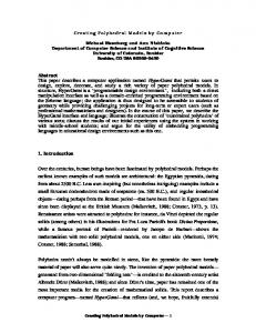
Figure 1. Main components of the stereolithography system and process of creating architecture models.
CAAD futures Digital Proceedings 1991
537
Technical features of computer-aided prototyping by stereolithography The stereolithography system combines three technologies: computer technology respectively computer-aided design, chemistry of photopolymer and, third, laser technology combined with scanner optics. The system consists of the following main components (see figure 1): -
-
a slice-computer, which successively generates horizontal cross sections of the CADmodel layer by layer (slices) and builds a pattern of vectors controlling the x/y-scanner (the z-dimension is realized by a mechanical elevator); an ultraviolet helium-cadmium-laser, which is moved across the liquid surface with a mirror controlled x/y-scanner; a liquid photopolymer, which changes to solid when the laser with a high selective intensity hits the liquid material; a process box, in which the process of polymerization is being executed; a post-curing chamber to realize a higher solidity of the plastic material after process.
The following steps are used to create a model: First, the user generates an object by his CAD-system. After having generated CAD-data, the data file can be used to build a stereolithography model. Some interface conditions have to be met: First, the model data file has to represent only volumes; second, the surfaces of each volume have to be oriented topologically, so that it is possible to distinguish the volume outside from the volume inside; third, all volume surfaces have to be - under geometrical topic - plane and triangular. How to solve some problems by using exemplary CAADsystems will be described in the next part of this article. When the required model data file exists, the computer generates a new data file, a 'slice file', with the pattern of vectors which are representing cross sections of the model. The operator - using a CAD-modul of the stereolithography system - selects and attaches a postsupport structure. This structure is built along with the part, holding it to the elevator, and supporting free-standing sections of the part (see figure 2). This completed CAD model, along with the support construction, is then passed over to the stereolithography unit, and the operator initiates the building program. Normally, after stereolithography process the model is post-processed with brief exposure to ultraviolet light in the post-curing chamber. Then, the model can be removed from the support structure, ready for further steps of processing. The exact building process works as follows: First, the support platform, i.e. the elevator, is positioned directly under the surface of the liquid plastic material. Then, the first slice will be hardened by the computer controlled scanner and laser. The laser beams the ultraviolet light in intervals of micro-seconds down to the liquid surface, where a great number of solid 'voxels', one per each laser impulse, develop. Between the light impulses, the laser is swept from one position to the other, so that all voxels form the desired slice at the end. In the next step, the elevator together with the first slice of the model sinks down into the liquid plastic material, so that the next slice can be formed. The measure of down
CAAD futures Digital Proceedings 1991
538
sinking depends on the diameter of the slice, which is adjustable between 0.25 and 0.7 mm. After forming the second slice, the third slice will be generated and so on. So, the model will be built from bottom to top. Due to the way the photopolymer model is built, sometimes it is necessary to construct a support design. Special model parts, which do not arise from bottom - from the elevator platform - to top cannot be constructed without supports. For that reason a full automatical process will not be feasible. In architectural models, for example, support constructions have to be built in case of hung ceilings or roof overhangs. In principle the model complexity only depends on the realizable diameter of the cross sections. The smallest realizable diameter is 0.5 mm, so that very complex model structures can be generated (the absolute minimum wall diameter is the width of the laser beam diameter; approximately 0.25 mm [6]). Therefore, it is not only possible to create simple walls, roofs or window openings, but also fine structure elements upon these main objects of architectural design. On the other hand this theoretical possibility is unlikely to be realized because the production of fine structures as volume entities requires much effort. Another limit of model configuration depends on the dimension of the stereolithography process box, in which the process of polymerization takes place. If the SLA-250 system is used, the size limit for the models will be 250 mm in a cube (a process box with 500 mm in a cube is available, too). Larger models can be produced in single parts or sections put together later. Additionally, the joins can be filled with liquid photopolymer getting solid in the postprocessing chamber (or in sunlight; this method is useful to repair model parts which are broken off from the model by carelessness). In architecture applications the joins can be left unfilled, in order to enable the look inside the buildings to see the order of all rooms. For this purpose, model buildings will regularly be built storey by storey.
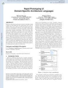
Figure 2. The stereolithography apparatus.
CAAD futures Digital Proceedings 1991
539
Available CAAD-systems and programming software-interfaces The method of building models by computer-aided prototyping has found application in mechanical engineering to build difficult prototype constructions. Architectural applications are still a great rarity. Up to now, there has not been any evaluation under the aspect of architectural design and questions of aesthetic manner have not been asked neither. The reason for this situation is that the method of stereolithography is still new (first presented in 1987) and very expensive. Nevertheless the stereolithography now seems to attract more attention as an important field of fundamental research in architecture. Three kinds of graphical software systems with different types of model structures are used in the current research project. One is a geographic information system to represent terrain models based on raster data, the other ones are architectural oriented design systems. If graphical software systems like these are to be applied in stereolithography, some interface conditions with a special data file structure, called STL-format, have to be considered: -
-
-
The data files have to represent volumes only; otherwise the computation of cross sections as a fundamental principle of the stereolithography method cannot be realized. All volumes must consist of plane surfaces (facets); other shapes are to be approximated to plane surfaces. All facets have to be oriented, so that it is possible to distinguish between volume inside and volume outside. The orientation will be realized by the point order of each facet polygon resp. by the direction of the normal vectors; in a right-handed coordinate system the outside surface is determined by a inverse clockwise order of each polygon. All these facets have to be exactly three-cornered in such a manner that between two endpoints of a polygon line a third point along this line must not exist; if necessary new three-cornered facets are to be added (see figure 3). All coordinate values have to be positive.
Figure 3. Generating a mesh of three-cornered facets of a polygonal surface.
CAAD futures Digital Proceedings 1991
540
Some new programs are to be written concerning the last two points especially. The STL-file needs the following structure writing in C terminology: char header [80]; unsigned long NUMFACETS;
/* 80 any given characters */ /* number of three-cornered facets */
/* next, storing 'NUMFACETS' three-cornered surfaces */ float i, j, k; float x0, y0, z0; float x1, y1, z1; float x2, y2, z2; unsigned short NUMATTR;
/* components of the normal vector */ /* coordinate triple of polygon point P0 */ /* coordinate triple of polygon point P1 */ /* coordinate triple of polygon point P2 */ /* number of attribute bytes (not used; value is seeting to 0) */
The following problems in different kinds of graphical software systems now are to be solved: a) Creating terrain models by using the geographic information system ERDAS ERDAS belongs to the category of raster oriented geographic information systems. The transformation of raster data in a stereolithography data file is not difficult, so that this geographic information system is very suitable for testing purposes. But the suitability of the stereolithography method to create terrain models as a special field of application can be verified, too. The procedure of creating a terrain model from a ERDAS GIS-file and the stereolithography system is as follows: The x/y-coordinates and the z size (representing the relief variations) of each pixel are known. As each pixel, geometrically, represents an area, and not exactly a point in mathematical mind, first all central points of each pixel will be set as vertices of a square gridded network. Subsequently the transformation in STL-file can start. Remembering the requirements of STL-files, the square grid is to be transformed in a mesh of triangles. For that reason the central point of each grid cell must be calculated, whereby the z value is derived by averaging the z values of the four neighboring grid points of the original network (see figure 4). After this procedure the triangular mesh of the surface relief is ready. Additionally, a triangular mesh of the four side planes and of the base plane is to be computed. Now the whole terrain model is complete as a volume, ready to build the physical model by stereolithography (see figure 5). Some further informations may be interesting: - In a first test a terrain model was planned with a size of 100*100 pixels. Later, a reduction onto 25*25 pixels was done, because computing had taken too much execution time. The reduced model came up to testing purposes.
CAAD futures Digital Proceedings 1991
541
- The number of triangles is to be calculated by the following formula: 4mn + 2(n + m) - 10, wherein n is the the number of pixels in x direction and m the number of pixels in y direction.
Figure 4. Generating a triangular mesh of a square gridded network based on a raster GIS.
Figure 5. Terrain model generated by stereolithography.
CAAD futures Digital Proceedings 1991
542
Hence it follows that by using data files within 1000*600 pixels (this value corresponds with usual GIS-maps) nearly 2,400,000 triangles and, with 50 bytes per each triangle, about 120 MB storage capacity is needed. The terrain model in figure 5 only needs about 130 KB as binary file. - The model size was chosen about 20*20 cm. Each pixel area represents 40 m in reality in scale of 1:5,000. b) Creating an architecture model by using a quasi volumetric based CAAD-system As to the structure of data files, the use of stereolithography to create architecture models requires higher qualities than it is necessary in the described GIS-system. A minimal condition is the existence of a CAAD-system based on a surface-oriented model structure. But it is better to use a volumetrically based CAAD-system, because the principle of stereolithography process is volume-oriented, too. The CAAD-system, which was used for testing purposes first, can be classified as a quasi volumetrically based system. This means, that the most important architectural details like walls, floors and ceilings, generated by user interface, are to be handled as volumes (in the used system all these entities are called "wall elements"; openings are stored as negative wall elements), but in the data file there doesn't exist a corresponding full volumetric storage model. Some architectural entities or design macros (f. e. staircase symbols in a groundplane) are stored as faces. But additionally, in the data files all 'volumes' can be identified by their topological polygon order, which implies the differentiation in volume inside and outside. So, for stereolithography applications, only detached faces are to be deleted (f. e. 2Dsymbols; see above). At last it is advantageous too, that in the data file all faces of each 'volume' are physically connected. Only if these faces were logically connected in a full volumetric model description, with corresponding file pointers from the data set containing the faces to the data set containing the volumes, the denotation of volumetric model could be used. Unlike the terrain model the technical interest in building architecture models aims at the effective use of the possibilites of hollow spaces as the most important form characteristic of computer-aided prototyping by stereolithography. Therefore, in a first test only a building with outer walls, roof, floor and some openings (windows, door) were constructed. In the next test, the inner walls, inner doors, staircases and some other building details were included, too. In both cases, Le Corbusier's building in the Weissenhofsiedlung of Stuttgart was modelled. To create both model versions, the following procedure was passed through: After using the CAAD-system to create the data file containing the original quasi volumetric data, this file is to be transformed in STL-file like described above. It is advantageous that similarities between the implemented "starbase"-interface of the CAADprogram and the needed STL-format of the stereolithography system can be used. Except for the polygon orientation (see above), the CAAD-system only knows triangles and four sided polygons. All volume surfaces, which have more than four polygon points, will automatically be devided into triangles by the program. Therefore, the situation in transforming the original data file should not be difficult. But three essential problems are to be solved by developing new software interfaces:
CAAD futures Digital Proceedings 1991 -
-
543
It is not sufficient to generate a new diagonal line if a four sided polygon is to be transformed into STL-format, because this polygon can be concave and the inconsistency of polygon orientations must be corrected (see figure 6). It is necessary to analyse all face polygons, if there are polygon points which belong to neighboring polygons. If such points are detected, they have to be included into the current face polygon, too.
Figure 6. Polygonal conditions on transformation into STL-format: a) generating a diagonal line is not sufficient; b) polygon orientation must be corrected.
-
As the polygon orientation of faces describing building openings is always turned contrary to the normal wall faces, the right orientation is to be computed.
If all these conditions comply with a program written in C (150 KB source program), the fully automatical conversion of the original data set in STL-format can start. Some additional informations may be of interest, too: -
The number of faces according the model shown in figure 7 is about 7000 (as mesh of triangles) with 320 KB storage capacity as binary STL-format. The data conversion from original CAD data to STL data format takes 180 minutes execution time using a 486 processor with mathematical coprocessor and 25 MHz (a first, non-optimized program
CAAD futures Digital Proceedings 1991
-
-
544
version was executed). The stereolithography process itself takes two days execution time. The size of Le Corbusier's Weissenhof-building was fixed at 14*9 cm (scale 1:100; maximum scale could be 1:30 using the stereolithography configuration with a process box of 50 cm in a cube). Costs range between 10,000 and 15,000 DM.
First the whole building was built in one process; storeys were not produced in single parts. The final model version with more details, inner walls and others is to be seen in figure 7 and 8. A pure surface-based CAAD-system will be used, too, although much more programming work than in comparison to a volumetric model is to be done.
Figure 7. Model of Le Corbusier's building in the Weissenhofsiedlung generated by stereolithography.
Evaluation under architectural design aspects and possible implications o n future CAAD environments After having discussed the technical features of stereolithography and the solution of problems in programming software-interfaces, now some questions under architectural design aspects must be answered. There are two arguments which show the necessarity of such reflections: First, the image of stereolithography models has a technical character like a mechanical workpiece sometimes; some critical questions about aesthetics cannot be settled sufficiently. Second, in future, reflections on all developments in CAAD will become more relevant to theoretical presuppositions of architecture [see Mitchell 1990, p. X]. Both points
CAAD futures Digital Proceedings 1991
545
of discussion are connected with the question of possible implications on future CAAD environments. From the view of architectural design, there are three different aspects, viz. the new procedure of making architecture models, the combination of this technique with graphically oriented CAAD-systems and, at last, the evaluation under an aesthetic aspect. Other criteria of evaluation like cost or needed manpower to work with the system will not be discussed here. And, of course, the important topic of ecological harmlessness of the photopolymer and the chemical process must be examined, too, but this cannot be cleared up in this paper. Following exemplary viewpoints are showing the new possibilities of this technique in building architecture models:
Figure 8. The first storey of the created architecture model: plotter output and realized model.
CAAD futures Digital Proceedings 1991
546
- The spectrum of realizable shapes is nearly unlimited. In principle all thinkable shapes, which can be produced traditionally by hand, are feasible by stereolithography. The shapes can be plane, curved or free formed. Volumes can be hollow or not. Openings and holes can be placed at any position. In the inner spaces of hollow volumes further volumes can be constructed. Fine and filigran structures upon the surfaces are realizable. Compared to the stereolithography method, alternative methods, f. e. using milling machines controlled by computers, are significantly limited in form generating. Possible restrictions due to the stereolithographic building process (see above) can be avoided by creating single parts of the model (avoiding roof overhangs by the construction of roofs without putting together at the walls). - A combination of solid photopolymer parts together with traditional material, which is usually taken for architectural models is thinkable, too. The model part construction with complicated forms (f. e. architectural surface structures like used by Frei Otto) can quickly be generated by computer-aided design. - In a double meaning, model parts are generated always exactly using this method: First, the method itself has a very inherent exactness, because the adjustable thickness of the cross sections which successively generate the model can be chosen smaller than 1 mm (see above). The second aspect, however, is more important: The architectural design and its graphical representation together with exact dimensioning can be transformed in a stereolithography model. The procedure is extensively automated, no manual step is included. Therefore, manipulations are reduced to a minimum. The most interesting advantage of the stereolithography method for architectural applications is the possibility of combining computer-aided architectural design with computer-aided construction of architecture models. Architects traditionally use two complementary kinds of design representation: drawings and architecture models. Up to now, only the graphical representation has been supported by computer technology, but not building architecture models. This gap has been filled, because now computers are able to generate both kinds of design representation in all complexity which is needed by architects:
CAAD futures Digital Proceedings 1991
547
Architects can apply design representation by computer generated architecture models in three important domains: - in architecture design competitions when a quickly generated physical model identical with the CAD data-file and graphics is wanted or needed; - to support real estate marketing, computer generated models could be a useful vehicle to persuade clients or art commitees; - as an alternative to graphical design representations whenever wanted. One can imagine that future CAAD-systems may offer these new possibilities: Architects will be able to create physical models directly from CAD-generated three-dimensional model data. It will be easy to implement a procedure into the CAD command environment, written in an easy-handling user programming language. User programming language means that the user can expand his CAD-system to any new purpose if desired, such like building architecture models (well concepted CAAD-programs contain user programming languages; and, of course, there exist some good arguments that architects, who use CAD-systems extensively, should learn programming techniques, too). If no full automatical process is possible, because free-standing sections are existing (see above), few interactive work steps will help; perhaps the development of knowledge-based systems as an integrated component of all powerful CAAD systems will reduce or solve some problems in future. The essential result of all considerations is that now architects have got a new tool in computer-aided design, which corresponds, beside drawings, to the traditional methods of architectural design representation. At last, some aesthetic considerations concerning the actual situation when applying this method shall be given: - The visual image of stereolithography models cannot satisfy all specific requirements for the aesthetics of architecture models. The colour of solid photopolymer is composed of yellow, beige and light-brown. It is translucent, but not clear and transparent. If the diameter of volume is chosen near minimum, the material appears white and more transparent. No other colours can be used. That means that the realizable colours are very restricted, and they have no equivalence to real architectural objects. - As the photopolymer plastic consists of homogeneous material, no differentiation by using other colours for some special details is possible. Therefore, fine or filigran structures are to be seen badly sometimes. - The surface of the model is rough due to the diameter-adjusted cross sections during the stereolithography process and uneven because there are photopolymer rests upon the model surface (see process of polymerization in figure 2). To remove the roughness, a manual subsequent treatment will be necessary (normally it must be done every time). The aesthetic deficiencies will continue to exist for a time. The situation could change, if the - just four-year old - technology will develop further. An important topic for architects will be the possibility in choosing different colours which can be realized during (!) the building process. It is thinkable that the polymer chemistry can help as follows: in future, the photopolymer molecules will have a specific structure which can vary by changing the wave-length of the laser beam. That would be a very promising way for applications in
CAAD futures Digital Proceedings 1991
548
architecture. But it is also true that a development in research fields of polymer chemistry and laser technology only for architectural/aesthetic purposes is not realistic without public research funds (architecture applications are too small in commercialization). But as long as no technological progress is to be seen, manual treatments can be done. So, varnishing or the use of illumination effects are able to improve the visual impression of architectural models. Finally, it can be remarked, that on the one hand the possibilities in design making and design representation will be expanded. Many design solutions generated by CAAD cannot only be visualized and verified by graphical representation but also by physical models. On the other hand the construction of architecture models as a domain of handicraft could be computerized successively. An analogous development to that having happened in graphical architectural representation could take place. This would be regrettable. But as long as this method is only regarded as one new tool beside others, it is acceptable for architects and their aesthetic pretensions, too. Conclusions The present article informs about first results of a research work entitled: "study of potentialities of the computer-aided prototyping in architecture and urban planning". First, the technical features of the new technology, the main components and the process of the stereolithography method are described. Then some conditions, restrictions and conclusions when using the stereolithography system are discussed. In the following part some informations about available CAAD-systems and programmed software-interfaces are given. Two graphical software systems are used: a geographic information system to create terrain models for urban and regional planning purposes and, second, a volumetrically based CAADsystem to create three-dimensional architecture models. Tests of interface together with a surface-based CAAD-system are just in work. The final part contains some remarks about aspects of architectural design using computer-aided prototyping and possible implications on future CAAD environments including some critical reflections on the matter. The general conclusion of all considerations is that creating architecture models by computer-aided prototyping is an important field for fundamental research in architecture. Many software interfaces connecting this new technology with diverse other CAAD-systems are to be programmed if necessary. Further research seems really promising because technology is still developing. The next step concerning architecture research will be the evaluation during application on architecture design competitions. Furthermore the integration in suitable CAAD-systems will be prepared. And, nevertheless, some technical improvements in applications for architects and urban planners will be set about. References Buchloh, C.: Steine räumlich denken. Stereolithographie für den Prototypenbau. iX 6/1990. Dötsch, E.: Mit StereoLithographie Modelle und Teile ohne Form. Kunststoffberater 10/1989. Mitchell, W. J.: Computer-Aided Architectural Design. New York 1977. Mitchell, W. J.: The Logic of Architecture. Design, Computation and Cognition. Cambridge, Mass. 1990. Newman, W. M. and R. F. Sproull: Principles of Interactive Computer Graphics. 2. Edition 1981. The 3D Systems, Inc.: StereoLithography Interface Specification. Valencia, CA, October 1989.