Simulink Based Architecture Prototyping of Compressed Domain MPEG-4 Watermarking Elias Kougianos1 , Saraju P. Mohanty2 , and Dhiraj K. Pradhan3 VLSI Design and CAD Laboratory, Computer Science and Engineering, University of North Texas, USA.1,2 Department of Computer Science, University of Bristol, UK.3 Email-ID:
[email protected] ,
[email protected] ,
[email protected] Abstract—We present a novel algorithm, architecture, and high-level Simulink prototyping for visible watermarking of MPEG-4 video streams. The watermark is inserted in the video stream during compression, resulting in an optimized compression/watermarking algorithm and system. Discrete Cosine Transform (DCT) watermarking, due to its robust nature, was chosen in this work to accomplish MPEG-4 video copyright protection. Drift compensation in the spatial domain is implemented for obtaining a stable watermark. The algorithm will be useful for insertion of broadcasters’ logo and subtitling in real-time applications such as sports broadcasting in digital TV.
I. I NTRODUCTION As broadband Internet becomes widely available, multimedia resources can be openly accessed, and can be distributed much more quickly and widely. From this trend, one can predict that as more and more songs, movies and images are exchanged on the Internet, download multimedia sales will eventually surpass traditional sales. This development could benefit the multimedia product owners, but also could challenge their ownership because most multimedia resources are distributed in unsecured formats. Moreover, this situation is further degraded by the fact that duplicating digital multimedia products is almost cost-free and instantaneous. To legal authorities, arbitrating the ownership of multimedia products is not easy, unless a mechanism can guarantee the genuine integrity of copyright. Multimedia watermarking is being investigated as a solution for copyright and intellectual property protection. Uncompressed or Broadcaster’s Logo Compressed Video Video
Compressed Image
Compressed Compress-Domain Visible-Transparent Watermarked Video Watermarking Video
Fig. 1. Real-time logo insertion through compressed domain watermarking.
There is a need for real-time copyright logo insertion in emerging applications, such as internet protocol television (IPTV). This is demonstrated in Fig. 1. The visible-transparent watermarking unit accepts broadcast compressed video and the broadcaster’s logo. The output is real-time compressed (MPEG-4) video with the logo embedded. This situation arises in IP-TV and digital TV broadcasting when video residing in a server has to be broadcast by different stations and under different broadcasting rights. Embedded systems that
are involved in broadcasting need to have embedded copyright protection. Existing works [1], [2] use invisible watermarking, not useful for logo insertion. Other existing works [3], [4] are for images not for video. MPEG-4 is the mainstream exchangeable video format in the Internet today because it has higher and flexible compression rate, lower bit rate, and higher efficiency while providing superior visual quality. The novel contributions of this paper are as follows: 1) A compressed-domain perceptual-based adaptive visible watermarking algorithm suitable for video broadcasting. 2) Application specific architectures for real-time watermarking in the context of compressed video (MPEG-4). 3) Simulink prototyping of the proposed architectures which can be integrated in multimedia producing appliances (e.g. digital camera, network processor). The paper is organized as follows: Section II discusses prior related research works. A new watermarking algorithm that inserts watermark in the compressed domain is introduced in Section III. In Section IV, we introduce proposed hardware architectures for compressed-domain watermarking architecture. High-level architectural Simulink prototyping and simulations are presented in Section V. Experimental results are presented in Section VI and conclusions are presented in Section VII. II. R ELATED P RIOR R ESEARCH Several watermarking algorithms have been presented in the current literature for various types of media. These algorithms, which are realized primarily as software, work offline; the multimedia information is first acquired and then the watermarks are inserted before the watermarked information is made available to the user. In this approach there is a time gap between multimedia capture and its transmission. The objective of this paper is to develop hardware assisted watermarking architectures and systems that bridge this gap. Many watermarking architectures are presented in the literature whose target is either low-power or real-time. In [5], [2] a spatial domain real-time watermarking scheme is proposed for television broadcast monitoring. In [6], a DCT domain invisible watermarking architecture is presented. In [3], a spatial-domain invisible-fragile watermarking architecture is proposed. In [4], a hardware architecture that can insert two visible watermarks in images in the spatial domain is introduced. In [7], an adaptive DWT (discrete wavelet transform) based visible watermarking architecture is proposed. In [8],
uncompressed domain visible watermarking architecture and FPGA prototyping is proposed. To advance the state-of-the art in video watermarking, a compressed-domain watermarking algorithm and architecture is proposed for MPEG-4 for realtime applications in this work. III. A C OMPRESSED D OMAIN V ISIBLE -T RANSPARENT WATERMARKING A LGORITHM FOR V IDEO The goal of the proposed compressed-domain visibletransparent video watermarking algorithm is adaptive fusion of watermark image (logo or subtitle) in the video frames in the compressed domain. There are several challenges that need to be addressed to obtain an effective watermarking scheme, such as: (1) selection of appropriate frame (I or B or P), (2) selection of particular region in a frame, (3) selection of watermark strength in a particular frame and across the frames, and (4) compensation of drifting in motion vectors. If C(i, j) are host video frame DCT coefficients and W (i, j) are watermark image DCT coefficients, then watermarked video frame DCT coefficients are obtained by [9]: CW (i, j) = αn × C(i, j) + βn × W (i, j),
(1)
where αn is the scaling factor and βn is the watermark strength factor. The relative values of αn and βn determine the strength of the watermark for the nth 8 × 8 block of a frame. Their values are computed based on characteristics of the host frame. For a particular frame, given that human perception is sensitive to image edge distortion, for edge blocks the value of αn should be close to its maximum value αmax while the value of βn should be close to its minimum value βmin . αmax and βmin are user defined parameters. Since the watermark DCT coefficients will be added to the video frame DCT coefficients, the strength of the watermark needs to be adjusted such that the distortion of these coefficients is minimal. Given that AC DCT coefficients of strongly textured blocks have small variance σn , it is desirable to make αn proportional to σn , and βn inversely proportional to σn . Therefore, for non-edge blocks: ³ ´ 2 αn = σ ∗ n × exp − (µ∗ n − µ∗ ) , ³ ´ ³ ³ ´´ (2) 1 ∗ ∗ 2 βn = × 1 − exp − (µ − µ ) . ∗ n σ n σ ∗ n is the normalized natural logarithm of the variance of the block’s AC DCT coefficients σn , given by: ´ ³ ¡ 1 ¢ P7 P7 ¡ ¢ ln(σn ) AC with σn = 64 σ ∗ n = ln(σ n (3) i=0 j=0 cij − µ max ) In Eqn. (3), σmax is the maximum value of all the σn in a frame, cij are the DCT coefficients, and µAC n is the mean value of the AC DCT coefficients in block n. In Eqn. (2), µ∗ n is the normalized mean value of the DC DCT coefficient in block n. mu∗ is the normalized mean value of all c00 (n) in a frame consisting of N 8 × 8 blocks. These are calculated as: ³ ´ ¡ ¢ PN (n) µ∗ n = cc00max and µ∗ = N1 × n=1 c00 (n). (4) Once the intra-frame parameter issue is solved as above, the next challenge is their determination for inter-frames. There
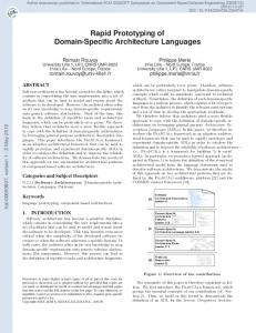
(a) Frame - 1, Watermark - 1 Fig. 2.
(b) Frame - 2, Watermark - 2
For compressed domain video watermarking, drifting is an Issue.
are several approaches including the following: First, calculate the parameters for each frame on the fly. However, it is a fact that continuous, real-time calculation of the values of αn and βn for each block within each frame being watermarked is very expensive in terms of resource requirements and processing time. Second, predetermine the parameters for benchmark frames, store them in a buffer, and use them on the fly. The second alternative is followed in this paper. One of the major issues of compressed domain watermarking is drifting. To comprehend the problem two test video clips with two different watermarks are presented in figure 2. As can be seen from the figure, for fast moving objects, if the drift compensation is not implemented effectively, the watermark (which is plain text for subtitling applications) is not legible. The proposed algorithm takes appropriate measures to address this issue. This is very important when subtitles are watermarked over video. The proposed watermarking algorithm is presented as a flow chart in Fig. 3. The step by step detailed pseudocode is presented in Algorithm 1. Watermarking in the compressed domain is follows the DCT module inside a DCPM/DCT video compression component module. The watermarking subjects here are not independent frames as still images, they are correlated frames with each other in temporal mode, i.e., inter frames (P or B) predicated from intra frame. So, every object in a base intra frame is inherited by predicted inter frames (P or B) such that the watermark in intra frame appears in inter frames (P or B) even though they are not embedded with the watermark. However, if it overlaps with any moving objects in the video scene, the watermark drifts around with the moving objects. To obtain a stable watermark, drift compensation is proposed to cancel the side effect [10]. The main concept is to extract the watermark drift in inter frames (P or B), and to cancel it by subtracting. A monochrome watermark image is embedded into Y color space only. For color watermark image embedding, all Y , Cb and Cr color spaces need to be watermarked, respectively. IV. T HE P ROPOSED WATERMARKING A RCHITECTURE The proposed architecture is presented in Fig. 4. It has 3 encoding branches: A, B and C. In branch A, the watermarking is inserted to all types of frames, i.e., I, B and P. So, in this branch, inter frames B and P have two watermarks: one is predicted from intra frame (I), and one is inserted. In branch
Algorithm 1 The compressed domain watermarking algorithm Video frames I, B, P
I, B, or P Frames?
Watermark Image
B or P Motion Motion Estimation Vector
DCT
DCT I Frame
Watermark Insertion Quantization Inverse Entropy Code Inverse Quantization
1: Input: Video RGB frames (N × M ), watermark monochrome 2: 3: 4: 5: 6: 7:
Zig Zag Entropy Code
8:
Inverse DCT Motion Motion Compensation Vector Drift Compensation Watermarking P/B Frame Fig. 3.
Output Buffer
Compressed Domain Visible Video Watermarking Algorithm Flow.
B, the watermark is inserted to I frame only. However, B and P have the same watermark by prediction. This watermark is the drifted one and need to be canceled in the inter frames. In branch C, the frames are compressed without any watermark. Thus, branch A has two watermarks, one is stable, another is drifted; branch B has one drifted watermark; branch C has no watermark. By subtracting branch B with branch C, the drifted watermark is extracted, and furthermore, by subtracting branch A with the extracted drifted watermark, the drifting watermark effect in inter frames is canceled. The purpose of branch C is to cancel encoding noise in the drift compensation result. Following are the main modules of the watermarking architecture: (1) Watermark embedding IBP, (2) Watermark embedding I, (3) Frame buffer, (4) Discrete Cosine Transformation (DCT), (5) Inverse DCT, (6) Motion estimation, (7) Motion compensation, (8) Quantization, (9) Inverse quantization, (10) Zig-Zag, (11) Inverse Zig-Zag, (12) Entropy coding, (13) Inverse entropy coding, and (14) Controller. Description of these modules is given below. 1) Watermark embedding IBP module: Embeds a watermark to every frame, I, B, P, sequentially. Inter frames B and P have two watermarks. One inherited from the intra frame, and one is embedded by the component module. The one inherited is the one drifting in inter frames (B and P). 2) Watermark embedding I module: Embeds a watermark to intra frame only. The inter frames (B and P) have the same one watermark in intra frame by prediction. If the watermark overlaps with moving objects, it will drift back and forth with the moving objects. 3) Frame buffer: Buffers the frames during intermediate computations by other modules. Its size capacity is sufficient for one input group of pictures, motion vectors, and the output stream. This is an external buffer which is different than the block memory used by the motion estimation module.
9: 10:
11: 12: 13: 14: 15: 16: 17: 18: 19:
20: 21: 22: 23: 24: 25: 26:
image (N × M ). Output: Watermarked MPEG-4 video stream. Convert RGB color frames to Y Cb Cr frames. Re-sample Y Cb Cr frames according to 4 : 2 : 0 sampling rate. Buffer GOP (15 continuous adjacent frames) of Y Cb Cr frames. Split Y frames into 16 × 16 blocks and Cb and Cr frames into 8 × 8 blocks. Perform motion estimate for Y frames. Rescale each 16 × 16 Y blocks to 8 × 8 blocks. If the even first frame (I) of GOP then go Step 11; If P frame then go to Step 8; If B frame then go to Step 10. Forward or Backward Motion Estimate Y frames with reference frames (I or P frames). Obtain the Motion Vectors and prediction errors of residual frame for Motion Compensation (MC). For Y frame go to Step 11; Find Cb / Cr Motion Vector and Prediction error. Go to step 11. Use bilinear algorithm to interpolate Y frame and B frame motion estimates with two P frames or I and P frames. Find the Motion Vectors (MV) and prediction errors of residual frame for Motion Compensation (MC). Perform 2-D DCT on blocks of frames from Step 11, 12, 13, 14. Perform 2-D DCT on the 1st 8 × 8 block for each 16 × 16 blocks of watermark image. Fuse Y of I, B, P frames with watermark image at DCT domain from Step 11, 12. Quantize 2-D DCT coefficient Matrix. Perform Zigzag scanning of quantized 2-D DCT Matrix. Entropy coding re-ordered 2-D DCT coefficient Matrix and Motion Vector. Send Cb and Cr frames to buffer. Perform entropy decoding Y frame. Perform inverse zigzag scanning. Perform inverse quantization. Perform inverse DCT. If B, P frames then predicate frame with reference frame, Motion Vector and run motion compensation with predication error. Go to Step 24. For original Y frame, run video compression without watermarking as above without step 12, 13. For original Y frame run video compression as above except just watermarking I frame at Step 13. Decode MPEG-4 stream from step 20, 21, respectively. Extract drifting watermark by subtracting decoded video frames between watermarked and un-watermarked frames from Step 22. Subtract IBP watermarked frames with drifting watermark frames. Repeat Steps 7,8,10,11,14,15,16 on Y frames again. Build structured watermarked MPEG-4 stream from buffer.
4) Discrete Cosine Transformation (DCT) or Inverse DCT module: Calculates the DCT coefficients of the video frames and it consists of two 1D DCT sub-modules. The algorithm from [11] is used for our implementation. The 1D row DCT of each 8 × 8 block is first computed. The column DCT of each block is then carried out. A buffer is used to assist in finding the transpose of the 1D row DCT. The controller for the watermarking unit controls the DCT module. The buffer stores 1D row DCT coefficient before column DCT is computed. 5) Motion estimation module: It is composed of motion detection and half pel modules. The macro block motion detection core performs a search for the best match for each macro block in the current frame based on a 3 × 3 macro
Watermark Image DCT
Input Video Frames
Frame Buffer
Controller Zig Zag
Quantization
Entropy Coding
Zig Zag
Quantization
Entropy Coding
Zig Zag
Quantization
Entropy Coding
Watermark Embedding I, B, P Watermark Embedding I Watermark Embedding
A
DCT
B
Datapath Control Signal
C
DCT
Inverse Entropy Coding
Inverse Zig Zag
Inverse Quantization
Inverse DCT
CMotion Compensation +
Inverse Entropy Coding
Inverse Zig Zag
Inverse Quantization
Inverse DCT
Motion B Compensation
Inverse Zig Zag Drift Compensation
Inverse Quantization
Inverse DCT
Motion A Compensation +
Inverse Entropy Coding
Fig. 4.
Motion Estimation
Quantization Zig Zag Entropy Coding Output Compressed Watermarked Stream
Schematic representation of proposed watermarking architecture.
block area in the previous frame. Pixel data are separated by component type, stored in off chip RAM, and macro blocks are processed one at a time. Each macro block results in a half-pel motion vector and a set of differences that could be sent on to additional stages for encoding. The motion detection core uses 16 block RAM modules and half pel uses 9 block RAM modules to do the exhaustive search. 6) Motion compensation module: Rebuilds a new frame resembling the original one by using reference frame, motion vectors, and prediction errors. If it is intra frame, this block is skipped. The input and output are buffered to the frame buffer. 7) Quantization module: Quantizes the DCT coefficients according to predefined quantization tables. The input and output are buffered to the frame buffer. 8) Inverse quantization module: Applies the quantization table and inverse quantization equations to resume the original 8×8 DCT coefficient matrix. The input and output are buffered to the frame buffer. 9) Zig-Zag Module: Performs zig-zag scanning of the DCT for re-ordering of the DCT coefficients. 10) Inverse Zig-Zag Module: Inverse zig-zag scanning also applies the zig-zag table to resume the original order of 8 × 8 DCT coefficient matrix. The input and output are buffered to the frame buffer. 11) Entropy coding module: Performs entropy coding which is implemented as Huffman coding look up. It has different submodules for variable length coding and pattern matching, etc. 12) Inverse entropy coding module: Applies the Huffman pre-calculated table as decoding lookup table. The input and output are buffered to the frame buffer. 13) Controller module: Generates clocked addressing and control signals to each individual component module in the system to synchronize system functions. The address bus and signals diagram showing the co-ordination of the architecture modules is shown in figure 5.
Water Mark Image
DCT
Water mark Buffer
Q
Z Z
Frame Buffer
M E
Entropy
Buffer
IDCT
IE
Address Bus
Fig. 5.
Controller
Output Buffer
IZ
IQ
MC
WM
Signals
System address and signals of the compressed domain architecture.
V. S IMULINK P ROTOTYPING This section discusses Simulink modeling of the individual architecture modules and the overall system architecture. A. System level modeling with Simulink To verify algorithm and architecture, firstly, a fast prototyping module is built with MATLAB/Simulink using function block sets. The methodology at this high level system modeling is top-down:MATLAB/Simulink build-in functions or block sets are used to create a top level conceptual system module, then each function is tuned in details, or new functional blocks are added. Both watermarking on uncompressed and compressed domains is investigated at this stage. B. System level modeling methodology Simulink offers common video and image processing functions and modules. The available function units are: DCT/IDCT, SAD for Motion Estimation, Block Processing (split), and Delay (Buffer). With minor work, Quantization, Zig-zag scanning and Entropy coding are built. Then the system level-modeling is accomplished as sub-tasks as follows: Sub-task 1: Color conversion and sampling rate compression, Sub-task 2: DCT domain compression in each frame, Subtask 3: Quantization and zig-zag scanning re-order, Sub-task
4: Entropy coding by looking up Huffman coding table, Subtask 5: Motion estimation and compensation only on I and P frames, Sub-task 6: Interpolating B frames, Sub-task 7: Uncompressed domain watermarking, Sub-task 8: Compressed domain watermarking without drift compensation, Sub-task 9: Drift compensation on compressed domain watermarking. C. Modeling of the Architecture The Simulink system block set diagram for MPEG-4 watermarking in the compressed domain is shown in figure 6. Figure 6(a) presents the overall architecture. The watermarking block in figure 6(b) embeds the watermark in all I, B and P frames. As estimate, the watermark in I frame also appears in B and P because they are predicted from I frame. It will result in two watermarks in non-intra frames. The watermark predicted from I frame will drift if it overlaps with moving objects in the scene. So drift compensation is applied to cancel the B and P’s watermark predicted from I frame. In figure 6(c), the block ”Encoder Y only I WM” compresses the original video and watermark I frame only. Another block ”Encode Y without WM” just compresses the original video, but does not embed the watermark. The two encoders’ difference is the drifting watermark. After decoding two video compression codes, the drifting watermark can be extracted by subtracting the above two videos. The ”Drift Compensation1” in figure 6(d) block cancels the drifting watermark on B and P by subtraction. From the above description, the conclusion is that above drift compensation works in the spatial domain.
(a) Overall Architecture
(b) The Watermarking Encoder
VI. E XPERIMENTAL R ESULTS This section discusses experiments which are performed for the architecture using various test videos and watermarks. We then discuss the performance of the architecture by analyzing the watermarked clips that are produced.
(c) The Watermarking Encoder YUV
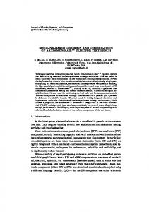
A. Test with video clips We performed exhaustive simulations to verify the proposed algorithms and architectures with a large variety of watermark images and video clips. For brevity, two sample watermarks are shown in figure 7 and selected examples of watermarked video are presented in figure 8. We introduced a different random sequence of AVI [12] video clips and similarly different watermark images to be embedded with the video clips, all having dimensions of 320 × 240. B. Testing of watermarking quality The standard video quality metrics mean square error (M SE) and peak-signal-to-noise-ratio (P SN R) are applied to quantify the system’s performance as [13], [11], [10]: PM PN P3 |p(m, n, k) − q(m, n, k)|2 , (5) M SE = m=1 n=1 k=1 µ i 3 ×2M ¶×N (2 − 1) P SN R = 10 × log10 , (6) MSE where p(m, n, k) and q(m, n, k) are the pixels after and before processing, respectively. The average PSNR of watermarked
(d) Drift Compensation Module Fig. 6. Simulink block set diagram for MPEG-4 compressed domain watermarking.
compressed video was ≈ 20dB to 30dB. The low PSNR did not degrade the perceptual quality of the video, as the low dB is due to the fact that the watermark logo inserted is visible and consequently becomes noise for the host video. The results are consistent with other visible watermarking algorithms and architectures available in the literature [4], [9], [8]. VII. C ONCLUSIONS AND F UTURE R ESEARCH We demonstrated an MPEG-4 watermarking system and algorithm. The architecture for the visible watermarking algorithm was prototyped using Simulink. The algorithm, architec-
(a) Original Bird Video
(b) Watermarked Bird
(c) Watermarked Bird
(d) Original Dinner
(e) Watermarked Dinner
(f) Watermarked Dinner
Fig. 8.
Selected sample videos used in the experiments.
[2] (a) Watermark -1 Fig. 7.
(b) Watermark -2 Sample Watermark Images.
ture, and its realization are suitable for real-time applications such as digital video broadcasting, IP-TV, and digital cinema. The watermarking techniques discussed in this paper also can embed color or animation watermark even though still monochrome watermark image is discussed here for simplicity. Blur or even disappearance of fast moving video objects after drift compensation could be caused by unsynchronized frames during extracting the drifting watermark. Further testing should be conducted, and a solution upon testing will be proposed. The watermark is embedded in compressed video, thus video processing can be done when one content provide sends compressed video to different broadcasting stations who then broadcast video with their logo without fully uncompressing the video. Further research is under way to extend the real-time performance of the system to HDTV and higher resolutions and to improve the P SN R. In future work, advanced MPEG-4 features, such as N-bit resolution, advanced scalable textures, and video objects will be utilized. Also, field-programmable-gate-array (FPGA) realization and then custom chip design will be performed. VIII. ACKNOWLEDGMENT The authors acknowledge UNT graduate Wei Cai. R EFERENCES [1] L. D. Strycker, P. Termont, J. Vandewege, J. Haitsma, A. Kalker, M. Maes, and G. Depovere, “Implementation of a Real-Time Digital
[3]
[4]
[5]
[6]
[7]
[8] [9]
[10] [11] [12] [13]
Watermarking Process for Broadcast Monitoring on Trimedia VLIW Processor,” IEE Proceedings on Vision, Image and Signal Processing, vol. 147, no. 4, pp. 371–376, Aug 2000. N. J. Mathai, D. Kundur, and A. Sheikholeslami, “Hardware Implementation Perspectives of Digital Video Watermarking Algortithms,” IEEE Transanctions on Signal Processing, vol. 51, no. 4, pp. 925–938, April 2003. A. Garimella, M. V. V. Satyanarayan, R. S. Kumar, P. S. Murugesh, and U. C. Niranjan, “VLSI Impementation of Online Digital Watermarking Techniques with Difference Encoding for the 8-bit Gray Scale Images,” in Proceedings of the International Conference on VLSI Design, 2003, pp. 283–288. S. P. Mohanty, N. Ranganathan, and R. K. Namballa, “A VLSI Architecture for Visible Watermarking in a Secure Still Digital Camera (S2 DC) Design,” IEEE Transactions on Very Large Scale Integration Systems, vol. 13, no. 8, pp. 1002–1012, August 2005. L. D. Strycker, P. Termont, J. Vandewege, J. Haitsma, A. Kalker, M. Maes, and G. Depovere, “Implementation of a Real-Time Digital Watermarking Process for Broadcast Monitoring on Trimedia VLIW Processor,” IEE Proceedings on Vision, Image and Signal Processing, vol. 147, no. 4, pp. 371–376, Aug 2000. T. H. Tsai and C. Y Wu, “An Implementation of Configurable Digital Watermarking Systems in MPEG Video Encoder,” in Proceedings of the IEEE International Conference on Consumer Electronics, 2003, pp. 216–217. Y. C. Fan, L. D. Van, C. M. Huang, and H. W. Tsao, “Hardware-Efficient Architecture Design of Wavelet-based Adaptive Visible Watermarking,” in Proceedings of 9th IEEE International Symposium on Consumer Electronics, 2005, pp. 399–403. S. P. Mohanty, E. Kougianos, W. Cai, and M. Ratnani, “Vlsi architectures of perceptual based video watermarking for real-time copyright protection,” in ISQED, 2009, pp. 527–534. S. P. Mohanty, K. R. Ramakrishnan, and M. S. Kankanhalli, “A DCT Domain Visible Watermarking Technique for Images,” in Proceedings of the IEEE International Conference on Multimedia and Expo, 2000, pp. 1029–1032. W. Cai, “FPGA Prototyping of a Watermarking Algortithms for MPEG4,” M.S. thesis, Univesity of North Texas, 2007. C. Loeffler et al., “Practical fast 1-D DCT algorithms with 11 multiplications,” in Proceedings of IEEE International Conference on Acoustics, Speech, and Signal Processing, 1989, pp. 988–991. “Xvid Codec,” http://www.xvid.org. J. Chen et al., Design of Digital Video Coding Systems - A Complete Compressed Domain Approach, Marcel Dekker, New York, 2002.