136
IEEE JOURNAL OF SOLID-STATE CIRCUITS, VOL. 44, NO. 1, JANUARY 2009
A 125 GOPS 583 mW Network-on-Chip Based Parallel Processor With Bio-Inspired Visual Attention Engine Kwanho Kim, Student Member, IEEE, Seungjin Lee, Student Member, IEEE, Joo-Young Kim, Student Member, IEEE, Minsu Kim, Student Member, IEEE, and Hoi-Jun Yoo, Fellow, IEEE
Abstract—A network-on-chip (NoC) based parallel processor is presented for bio-inspired real-time object recognition with visual attention algorithm. It contains an ARM10-compatible 32-bit main processor, 8 single-instruction multiple-data (SIMD) clusters with 8 processing elements in each cluster, a cellular neural network based visual attention engine (VAE), a matching accelerator, and a DMA-like external interface. The VAE with 2-D shift register array finds salient objects on the entire image rapidly. Then, the parallel processor performs further detailed image processing within only the pre-selected attention regions. The low-latency NoC employs dual channel, adaptive switching and packet-based power management, providing 76.8 GB/s aggregated bandwidth. The 36 mm2 chip contains 1.9 M gates and 226 kB SRAM in a 0.13 m 8-metal CMOS technology. The fabricated chip achieves a peak performance of 125 GOPS and 22 frames/sec object recognition while dissipating 583 mW at 1.2 V. Index Terms—Matching accelerator, network-on-chip (NoC), object recognition, parallel processor, processing element clusters, visual attention engine.
I. INTRODUCTION ECENTLY, intelligent vision processing such as object recognition and video analysis has been emerging research area for intelligent mobile robot vision system, autonomous vehicle control, video surveillance and natural human-machine interfaces [1]–[4]. Such vision applications require huge computational power and real-time response under the low power constraint, especially for mobile devices [1], [2]. Programmability is also needed to cope with a wide variety of applications and recognition targets [2]. Object recognition involves complex image processing tasks which can be classified into several stages of processing with different computational characteristics. In low-level processing (e.g. image filtering, feature extraction), simple arithmetic operations are performed on a 2-D image array of pixels. On the contrary, high-level processing is irregular and performed
R
Manuscript received April 15, 2008; revised August 31, 2008. Current version published December 24, 2008. This work was supported by the MIC (Ministry of Information and Communication), Korea, under the ITRC (Information Technology Research Center) support program supervised by the IITA(Institute for Information Technology Advancement) (IITA-2008-(C1090-0801-0012). The authors are with the Division of Electrical Engineering, Department of Electrical Engineering and Computer Science, Korea Advanced Institute of Science and Technology (KAIST), Daejeon 305-701, Korea (e-mail:
[email protected]). Digital Object Identifier 10.1109/JSSC.2008.2007157
on objects that are defined by groups of features extracted at the lower level. Since object recognition requires huge computation power on each stage, general-purpose architectures such as microprocessor and digital signal processor cannot achieve a real-time processing due to its sequential pipelining feature. Many vision processors previously reported were based on massively parallel SIMD architecture with a number of processing elements (PEs) for data-level parallelism [1]–[3]. However, these processors focus only on the low-level image processing operations like image filtering, and they are not suitable for object-level parallelism, which is essential for higher level vision applications such as object recognition. A multiple-instruction multiple-data (MIMD) multi-processor was presented with Network-on-Chip (NoC) to exploit task-level parallelism [4]. However, it cannot achieve a real-time processing due to its limited computing power and complex data synchronization requirement. In this work, to overcome the computational complexity of the object recognition, visual attention based object recognition algorithm is applied to design the pattern recognition processor [5]. The processor of this study combines 3 features, the parallel processor, visual attention engine (VAE) and the NoC platform, and improves object recognition performance: 58% reduction in power and 38% improvement in recognition speed over the previous design [4]. Its SIMD/MIMD dual-mode parallel processor contains 8 SIMD linear array PE clusters which have 8 PEs each, achieving the peak performance of 96 GOPS. The VAE is composed of an 80 x 60 digital cellular neural network (CNN) and selects salient object regions out of the image rapidly. The NoC supports 76.8 GB/s aggregated bandwidth with 2-clock cycle latency as a communication platform. The chip is fabricated in 0.13 um CMOS technology and shows 125 GOPS peak performance at the recognition speed of 22 frames/sec with less than 583 mW. This paper is organized as follows. In Section II, the attention-based object recognition is briefly introduced. The system architecture with dual-mode configuration will be described in Section III. Key building blocks such as the VAE, SIMD PE Clusters, low-latency NoC, and matching accelerator will be explained in Section IV–VII. Packet-based power management employed in this chip is described in Section VIII. Implementation results and performance evaluations are given in Section IX. The conclusion of this work will be made in Section X.
0018-9200/$25.00 © 2008 IEEE Authorized licensed use limited to: Korea Advanced Institute of Science and Technology. Downloaded on January 13, 2009 at 10:12 from IEEE Xplore. Restrictions apply.
KIM et al.: A 125 GOPS 583 mW NETWORK-ON-CHIP BASED PARALLEL PROCESSOR WITH BIO-INSPIRED VISUAL ATTENTION ENGINE
137
Fig. 1. Attention-based object recognition system.
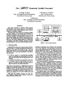
II. ATTENTION-BASED OBJECT RECOGNITION A. Algorithm Overview The proposed attention-based object recognition algorithm consists of three steps (Fig. 1): visual attention, key-points extraction and matching. In contrast to the conventional object recognition algorithm such as Scale Invariant Feature Transform (SIFT) [6], visual attention is performed in advance. Visual attention is the ability of the human visual system to rapidly select the most salient part of an image. It is an essential role of visual cortex in the human brain [7]. Then, key-points extraction and feature descriptor generation are performed on the pre-selected salient image regions by the visual attention mechanism. Finally, we can recognize the object by matching individual features to a database of features using a nearest neighbor search algorithm [8]. By incorporating the visual attention into the conventional object recognition algorithm, next visual processing such as key-point extraction and matching can focus on only the pre-selected image to reduce the computation cost of the object recognition. The visual attention can confine other image processing tasks within the extent of the interested image regions. Therefore, the amount of the image data to be processed on higher-level visual processing stages can be reduced and the computation cost can go down. The number of key-points extracted in the image is reduced and the key-points only in the attended image region need to be matched to the object database, making it faster and easier to recognize the object. As a result, the VAE leads to a considerable speed-up to make real-time object recognition possible. Moreover, numerous computer vision applications such as object tracking and image segmentation can benefit from the VAE as well. B. Cellular Neural Network for VAE Saliency-based model of visual attention has been widely used in various computer vision applications [9], [10]. According to the [9], visual attention can be modeled by the
four steps: multi-scale image generation, low-level feature extraction, conspicuity map, and saliency map generation. Such a saliency-based visual attention process involves a series of 2-D image filtering operations such as difference-of-Gaussians filter and Gabor filter, which can be easily implemented by an algorithm with CNN architecture [11]. The CNN is a 2-D array of locally connected cells and the connection weights among neighboring cells as a template define the CNN operation [12]. Because 2-D structure of the CNN can be directly mapped onto an image, its inherent cell-level parallel processing can give high performance. In addition, uniform local connections make it suitable for VLSI implementation. Therefore, the VAE of this study is implemented using the CNN. III. SYSTEM ARCHITECTURE A. System Operation Fig. 2 shows the overall architecture of the proposed NoCbased parallel processor. It consists of 12 IPs: a main processor, VAE, a matching accelerator, 8 PE Clusters (PECs) and an external interface. The ARM10-compatible 32-bit main processor controls the overall system operations. The VAE, an 80 x 60 digital cellular neural network, rapidly detects the salient image regions on the sub-sampled image (80 x 60 pixels) by contour and saliency map extraction. Although the low-resolution image is mapped on the VAE, it does not cause any loss of recognition accuracy because the role of the VAE is just to make a rough selection of the salient image regions before the detailed processing. The 8 linearly connected PECs perform data-intensive image processing applications such as image gradients and histogram calculations for more detail analysis of the salient image parts (i.e., the objects) selected by the VAE. The matching accelerator boosts the nearest neighbor search to obtain the final recognition result in real-time. The DMA-like external interface distributes automatically the corresponding image data to each PEC to reduce system overhead. Initially, 2-D image plane is equally divided into 8 PECs according to the image size specified by the main processor. Each core is connected to the NoC
Authorized licensed use limited to: Korea Advanced Institute of Science and Technology. Downloaded on January 13, 2009 at 10:12 from IEEE Xplore. Restrictions apply.
138
IEEE JOURNAL OF SOLID-STATE CIRCUITS, VOL. 44, NO. 1, JANUARY 2009
Fig. 2. System architecture.
Fig. 3. Dual-mode configuration: (a) SIMD mode and (b) MIMD mode.
via a network interface (NI). The on-chip PLL generates two independent clocks for the IPs and the NoC, and the clocks can be controlled by the host processor. B. Dual-Mode Configuration The attention-based computer vision applications such as object recognition and tracking require a wide range of parallelism: data-level parallelism for the processing of the entire image in the pre-attentive phase, and object-level parallelism for only salient image regions selected by the VAE in the post-attentive phase. To incorporate the above requirements into a single system, the proposed parallel processor has dual-mode configuration. That is, by modifying its NoC configuration, the system can choose one mode between SIMD and MIMD mode as shown in Fig. 3. In a circuit switching NoC, the main processor broadcasts instruction and data to all PE arrays. In this mode, the system exploits massively parallel SIMD operation for image pre-processing, and in this case its peak performance is 96 GOPS at 200 MHz. On the contrary, in a packet switching NoC or in the MIMD mode, the 8 PECs operate independently in parallel for object-parallel processing. In this case, each PEC is responsible for the objects, each of which contains image data around the extracted key-points. It takes about a few tens of cycles to change the NoC configuration and the exact cycles depend on the network traffic status due to circuit establishment and release time overhead for the
Fig. 4. Block diagram of the VAE.
circuit switching NoC. For object recognition application, however, the operation mode conversion occurs only twice when the recognition of 1-frame image is performed: SIMD to MIMD conversion after the pre-processing stage including the VAE operation and MIMD to SIMD conversion after completing the recognition. Therefore, such a dual-mode architecture is suitable for compact object recognition system with negligible impact on the overall system performance. IV. VISUAL ATTENTION ENGINE A. Cellular Neural Network Based Architecture The CNN is usually implemented using analog cells because biological neuron operates in a continuous time domain [13]. However, the analog CNN requires high accuracy analog circuits to deal with complex algorithms like visual attention and it is not suitable to be integrated into SoC. To overcome the limitation of the analog CNN, a digital CNN, a discrete-time
Authorized licensed use limited to: Korea Advanced Institute of Science and Technology. Downloaded on January 13, 2009 at 10:12 from IEEE Xplore. Restrictions apply.
KIM et al.: A 125 GOPS 583 mW NETWORK-ON-CHIP BASED PARALLEL PROCESSOR WITH BIO-INSPIRED VISUAL ATTENTION ENGINE
139
Fig. 5. VAE cell schematic.
version of CNN, has been studied [14]. The digital CNN can be more easily integrated into the parallel processor without analog-to-digital (A/D) or digital-to-analog (D/A) conversion overhead. The VAE is an 80 x 60 digital CNN optimized for small area and energy efficiency. Fig. 4 shows the block diagram of the VAE, which is composed of 4 arrays of 20 x 60 cells, 120 visual PEs (VPEs) shared by the cell arrays, and a controller with 2 kB instruction memory. Previous implementations of digital CNN [14] can integrate only a small number of cells due to the large size of digital arithmetic blocks. On the contrary, the VAE integrates 80 x 60 cells that each correspond to a pixel in an 80 x 60 resolution image. This is possible because the cells of the VAE only perform storage and inter-cell data transfer to minimize area while a smaller number of the shared VPEs are responsible for processing the cells data. An 80 x 60 shift register array, distributed among the cells, eliminates data communication overhead in convolution operations of arbitrary kernel size and shape, which is the most frequently used operation in the CNN. The VAE controller generates the control signals for sequencing the operation of the cells and the VPEs. Such a CNN-based architecture can accelerate visual attention algorithms like contour and saliency map extraction. B. VAE Cell Fig. 5 shows the schematic diagram of the VAE cell. It consists of two elements: a 8-bit 4-entry register file and a 4-directional shift register. Four 6T SRAM cell based registers store intermediate and result data of the CNN operation. The shift register’s data is initially loaded from the register file and then shifted to neighboring cells. A shift operation on the entire cell array requires only 1 cycle to complete. Because all cells shift in the same direction, one bidirectional channel is used for 2-way communication between neighboring cells to save routing channels. A dynamic logic based on MUX/DEMUX with NMOS pass-transistor only circuit is utilized to reduce the area of the
4-directional shift register. In this circuit, the voltage value at and then is evaluated dynamic node D is precharged to through one of five possible paths selected by the control signals ‘N_En’, ‘E_En’, ‘S_En’, ‘W_En’, and ‘load_En’ before being captured by the pulsed latch. As a result, the full-custom de, achieving the signed cell occupies a compact area of 502 cell area reduction of 40% compared with a static MUX-based design. C. VAE Operation Fig. 6(a) shows the basic VAE operation. Each VPE located in the middle is shared by a group of 40 cells connected via 2 read buses and 1 write bus. The VPEs, operating in SIMD mode, are capable of 1 cycle MAC operation and employ 3 stage pipelines that consist of read, execute, and write. The cell data stored in the shift register and the register file can be read through 2 read buses. Execution results of the VPEs are written back to the register file of the cell through a write bus. The single-ended read and the complementary write bus bus is pre-charged to driven by the output of the VPE has full swing signal to ensure reliable write operation. To facilitate 1 op/cycle throughput, read and write of cell data is sequentially executed within one cycle using a self-timed circuit. It takes 42 cycles for the VPEs to execute one instruction on the entire cell array. The resulting peak performance of the 120 VPEs is 24 GOPS at 200 MHz. Fig. 6(b) shows the measured waveforms of cell control signals when the VAE operates at 200 MHz. Word line, read enable, and write enable signals are sequentially asserted for cell read and write operation within a single cycle. Thanks to the VAE pipelined operation, 1-cycle throughput and the peak performance of 24 GMACS are achieved. The most time consuming operation of the digital CNN is to calculate the weighted sum of neighborhood cell values. Fig. 7 visualizes the method to obtain the weighted sum. It involves a spiraling shift sequence that can be straightforwardly extended to neighborhoods larger than the 3 x 3 neighborhood of Fig. 7.
Authorized licensed use limited to: Korea Advanced Institute of Science and Technology. Downloaded on January 13, 2009 at 10:12 from IEEE Xplore. Restrictions apply.
140
IEEE JOURNAL OF SOLID-STATE CIRCUITS, VOL. 44, NO. 1, JANUARY 2009
Fig. 6. (a) VAE operation and (b) measured waveforms of cell control signals.
The procedure shown in Fig. 7 takes 387 cycles (42 cycles per MAC operation and 1 cycle per shift operation) to complete the weighted sum operation on the VAE. Thanks to the efficient shift pattern and a single cycle shift operation, data communication overhead is only 2.4% and 93% utilization of the VPE array can be achieved. For a complete iteration of a 3 x 3 CNN template, 858 cycles or 4.3 s is required. As a result, the VAE takes only 2.4 ms to complete a saliency map extraction, which is about two orders of magnitude improvement over that by an Intel Core 2 processor. V. SIMD PE CLUSTER The PEC is a SIMD processor array designed to accelerate image processing tasks. Fig. 8 shows the architecture of the PEC. It contains 8 linearly-connected PEs controlled by a cluster controller, a cluster processing unit (CLPU), 20 kB local shared memory (LSM), a LSM controller, and a PE load/store unit. The 8 PEs operate in a SIMD fashion and process image operations in a column-parallel (or row-parallel) manner. The CLPU, which consists of an accumulator and an 8-input comparator, generates a single scalar result from the parallel output processed by the PE array. The LSM is used as on-chip frame memory or local memory for each PEC to store the input or processed image data and objects. A single-port 128-bit wide SRAM is used for the LSM to avoid area overhead. The LSM
provides a single-cycle access and is shared among the PE load/ store unit, the LSM controller and the CLPU. Arbitration for the LSM is performed on a cycle-by-cycle basis to improve the LSM utilization. The LSM controller is responsible for data transfer between external memory or other PECs and the LSM while the PE load/store unit can access the LSM only for local data transfer. The LSM controller, which is an independent processing unit optimized for data transfer like the DMA engine, enables the data transfers in parallel with PE execution to hide excessive external memory latency. Fig. 9 shows the 5-stage pipeline architecture of the PEC. The cluster controller, the 3-stage pipelined PE array, and the CLPU are tightly coupled together to maintain 1-cycle throughput for all operations. Especially, the tightly coupled PE array and CLPU architecture achieves single-cycle execution for statistical image processing tasks (e.g. histogram calculations) where an input image is transformed into a scalar or vector data, while the massively parallel SIMD processors [1], [2] require sequential operations on a line-by-line basis to obtain the same result due to the absence of the CLPU-like processing unit. Such an architecture is suitable for object recognition because histogram calculations is the essential operation for key-point descriptor generation in the object recognition task [6]. In addition, due to the simple control circuit in the SIMD architecture, the cluster controller including 2 KB instruction
Authorized licensed use limited to: Korea Advanced Institute of Science and Technology. Downloaded on January 13, 2009 at 10:12 from IEEE Xplore. Restrictions apply.
KIM et al.: A 125 GOPS 583 mW NETWORK-ON-CHIP BASED PARALLEL PROCESSOR WITH BIO-INSPIRED VISUAL ATTENTION ENGINE
141
Fig. 7. Spiral shift sequence for CNN operation on the VAE.
Fig. 9. Tightly-coupled PEC pipeline architecture. Fig. 8. Block diagram of the PE cluster.
memory occupies only 6% of the total PEC area, which results in high computation efficiency. Each PE utilizes 4-way very long instruction word (VLIW) architecture to execute up to 4 instructions in a single cycle as shown in Fig. 10: three instructions for data processing and one instruction for data transfer. It consists of two 16-bit ALUs, a shifter, a multiplier and a 16-bit 10-port register file. All PE instructions have single-cycle execution except 16-bit multiplyaccumulate (MAC) operation, which has a two-cycle latency. The 16-bit datapath units of the PE can be configured to execute two 8-bit operations in parallel for gray-scale image processing. The left and right neighbor PE registers can be directly accessed in a single-cycle using the linearly connected PE array for efficient inter-PE communication, which is one of the most frequently used operations for neighborhood image processing tasks such as image filtering. Meanwhile, memory ac-
Fig. 10. Block diagram of 4-way VLIW PE.
cess patterns are well predictable for such low-level image processing tasks due to the characteristics of regular and pre-defined data accesses. The 4-way VLIW PEs allow PEC software to pre-fetch the needed data in advance without performance degradation by executing data transfer and processing instructions concurrently.
Authorized licensed use limited to: Korea Advanced Institute of Science and Technology. Downloaded on January 13, 2009 at 10:12 from IEEE Xplore. Restrictions apply.
142
IEEE JOURNAL OF SOLID-STATE CIRCUITS, VOL. 44, NO. 1, JANUARY 2009
Fig. 11. NoC packet format.
VI. LOW-LATENCY NETWORK-ON-CHIP For attention-based vision applications, image regions of interest are pre-selected by the VAE in SIMD mode. After the pre-attentive stage, each PEC handles the selected image regions on a per-object basis in MIMD mode. In order to facilitate object-level parallel processing, a large amount of data transactions among the PECs is required to redistribute the image data of the object to the corresponding PEC. We apply the NoC to secure the huge communication bandwidth required for parallel computing. A. NoC Protocol Regular topology NoC (e.g. mesh, torus) has been widely used because of its better scalability and higher throughput [15]. However, most of SoCs are heterogeneous with each core having different communication requirements. Therefore, the NoC topology should be decided based on the traffic characteristics of the SoC to achieve high performance and low cost [16]. In this work, the tree-based NoC with 3 star-connected crossbar switches is used for lower latency and power than a 2-D mesh NoC. Fig. 11 shows the NoC packet format. A wormhole switching, where each packet is divided into a few 32-bit FLITs (FLow control unIT) with additional 3-bit control signals, is employed to reduce buffer requirements. Header FLIT contains 4-bit burst length information for burst packet transaction up to 256-bit (8 x 32-bit) data and 2-bit priority information for quality-of-service (QoS) control. A handshaking protocol is supported for reliable transmission by using an acknowledgement request (AC) bit in the packet header. The packet length is determined by the burst length and maximum 10 FLITS are possible. Deterministic source routing scheme is used for simple hardware implementation. Circuit and packet switching are adaptively selected for a specific route path from the main processor to the PECs in order to support dual-mode configuration. A 1-bit sideband back-pressure signal is used for the flow control in the NoC. The back-pressure signal is asserted to stop the packet transmission when buffer overflow occurs, or when destination PE cannot provide the required service.
B. Low-latency Crossbar Switch Fig. 12 shows the block diagram of the proposed low-latency crossbar switch. A 7 x 7 crossbar switch is optimized for low-latency and energy efficiency with two key features: adaptive switching and dual mode channel. At port 0, the switch supports both circuit and packet switching adaptively according to the system operation mode. In circuit switching mode, burst packet can be broadcasted to all PECs by bypassing the 8-FLIT queuing buffers and arbiter, resulting in reduced delay and energy dissipation. An input driver at port 0 dynamically controls its drive strength based on the output load associated with the switching mode for reliable packet transmission. At port 1 through 6, dual mode channel is adopted to reduce packet latency, especially for return packets transferring from slave IPs. The return packet latency seriously affects the overall system performance because the PEC with in-order execution stalls until the return packet arrives. Incoming return packets, detected by a pre-route unit, are ejected immediately after a 1 flit buffer through an additional image-express channel. This mechanism saves 2 pipeline stages of the switch by eliminating unnecessary packet queuing, arbitration, and crossbar fabric traversal. Fig. 13(a) shows the 4-stage low-latency crossbar switch pipeline. Incoming return packets are ejected 2-cycle earlier than normal packets without any flow control. Because return packets are mostly burst packets, this scheme is more effective. The crossbar switch with the dual mode channel does not store the return packets at queuing buffers. They are directly injected into the network without any suppression by the back-pressure flow control, which leads to a significant performance improvement over a conventional crossbar switch [4]. Measured waveforms (Fig. 13(b)) show the low-latency return packet transmission by the crossbar switch with dual mode channel when the NoC operates at 200 MHz. As a result, 26% latency reduction and 33% energy reduction are obtained with only 6% area overhead compared to the conventional crossbar switch [4] while various image processing applications are running on the NoC-based system.
Authorized licensed use limited to: Korea Advanced Institute of Science and Technology. Downloaded on January 13, 2009 at 10:12 from IEEE Xplore. Restrictions apply.
KIM et al.: A 125 GOPS 583 mW NETWORK-ON-CHIP BASED PARALLEL PROCESSOR WITH BIO-INSPIRED VISUAL ATTENTION ENGINE
Fig. 12. Proposed low-latency crossbar switch.
Fig. 13. (a) Crossbar switch pipeline and (b) measured waveforms.
Authorized licensed use limited to: Korea Advanced Institute of Science and Technology. Downloaded on January 13, 2009 at 10:12 from IEEE Xplore. Restrictions apply.
143
144
IEEE JOURNAL OF SOLID-STATE CIRCUITS, VOL. 44, NO. 1, JANUARY 2009
Fig. 14. FLIT-level clock gating.
C. Synchronization A first-in-first-out (FIFO) based synchronizer is designed to interface between the IPs and the NoC with independent clock frequencies and phases. Without global synchronization, packet transmission is performed by source synchronous scheme in which a strobe signal is transmitted along with the packet data [16]. A 4 FLITs depth FIFO captures the incoming FLIT using the delayed strobe signal. Detection of the full or empty status is accomplished using the FIFO write and read pointers to avoid FIFO overflow or underflow, respectively. The synchronizer is placed at the first stage of the crossbar switch pipeline. D. FLIT-Level Clock Gating FLIT-level fine-grained clock gating is used to reduce NoC power consumption as shown in Fig. 14. Only the required packet routing path is activated on a per-port basis. A power control unit that monitors an incoming packet header is always turned on and the output port number is encoded to control the NoC clock signal. The clock gating signals are generated on all pipelining stages of the crossbar switch in a pipelined manner. Only queuing buffer at port N, arbiter and crossbar fabric at port M are enabled when a FLIT is transferred from an input port N to an output port M. Since queuing buffers, built using a number of flip-flops, are the most power-consuming unit in the NoC, the FLIT-level power management can reduce NoC power consumption by 32% without degradation of throughput and latency. VII. MATCHING ACCELERATOR In nearest neighbor search algorithm, the most time consuming part is the distance calculation between input vector and database vector. In this work, sum of absolute differences (SAD) is used for the distance metric. The proposed matching accelerator aims at accelerating the nearest neighbor search algorithm to get a final recognition result in real-time. Fig. 15 shows the overall architecture of the proposed matching accelerator [8], which consists of RISC core, pre-fetch DMA, and two 8 kB 256-bit wide database vector (DB) memories. The RISC core manages the overall operations of the matching accelerator and performs the nearest neighbor search algorithm.
The pre-fetch DMA initiated by the RISC core transfers external object database to the internal DB memory via the NI. 2-stage pipelined tree structure SAD accumulation logics are merged into the DB memory in order to resolve a throughput bottleneck caused by bandwidth conversion between 256-bit vector data and 32-bit scalar RISC core. By accumulating four absolute difference results per stage, 16 absolute difference results are accumulated into 32-bit scalar value in every cycle at 200 MHz. As a result, the SAD merged memory logics perform the distance calculation between two 256-bit (16-bit 16-dimension) vectors by 2-cycle latency and 1-cycle throughput at 200 MHz, which enables a real-time nearest neighbor matching. VIII. PACKET-BASED POWER MANAGEMENT The modular and point-to-point NoC approach makes it easy to manage the overall system by decoupling computation of IPs from inter-IP communication, which enables efficient power management techniques compared to the bus-based system. For low power consumption, our chip performs packet-based power management at the IP level as shown in Fig. 16. Each PE cluster can be individually enabled or disabled according to the framing signals of the packet to cut the power consumption by the inactive IPs. The valid signals generated by the network interface wake up the related blocks within the IP only when incoming packet arrives. 4 clock domains of the PE cluster are individually controlled based on the issued instruction types. During the image data transfer phase for which only the LSM controller needs to be activated, the clock signals of the PE register files are gated-off and operand isolation to the PE datapath prevents unnecessary signal transitions to reduce power consumption. Since the PE datapath and register files occupy about 62% of the total power consumption, the power reduction up to 27% can be achieved when the object recognition application is running. IX. IMPLEMENTATION AND EXPERIMENTAL RESULTS The proposed NoC-based parallel processor is fabricated in a 0.13 m 1-poly 8-metal standard CMOS logic process, and its die area takes 6 x 6 mm including 1.9 M gate count and 228 kB on-chip SRAM. The chip micrograph is shown in Fig. 17 and Table I summarizes the chip features. Operating frequency of the chip is 200 MHz for the IPs and 400 MHz for
Authorized licensed use limited to: Korea Advanced Institute of Science and Technology. Downloaded on January 13, 2009 at 10:12 from IEEE Xplore. Restrictions apply.
KIM et al.: A 125 GOPS 583 mW NETWORK-ON-CHIP BASED PARALLEL PROCESSOR WITH BIO-INSPIRED VISUAL ATTENTION ENGINE
145
Fig. 15. Block diagram of the matching accelerator.
TABLE I PERFORMANCE SUMMARY
Fig. 16. Packet-based power management.
TABLE II POWER BREAKDOWN
Fig. 17. Chip micrograph.
the NoC. The power consumption is about 583 mW at 1.2 V power supply while object recognition application program is running at 22 frames/sec. Table II shows the power breakdown of the chip. The NoC consumes 9% of the die area and 8% of the power consumption, which means that the NoC cost is amortized over the processing units. Fig. 18 shows the comparison with the previously reported parallel processors in terms of power efficiency [1], [2], [4], [17]. All data is scaled to 0.13 m technology. For the equal comparison, GOPS/W and nJ/pixel are adopted as a performance index for the normalization. As a result, the chip achieves
up to 4.3 times higher GOPS/W in case of 8-bit fixed-point operation and energy per pixel reduction up to 42% is obtained for object recognition task with the help of the VAE and the packet-based power management compared with other parallel processors. Fig. 19 shows the performance evaluation when the attention-based object recognition is performed on the chip. In this example, the VAE extracts a CNN-based saliency map as the attention cues and 50 objects are used as the database for pattern matching. The VAE takes only 2.4 ms to complete saliency map
Authorized licensed use limited to: Korea Advanced Institute of Science and Technology. Downloaded on January 13, 2009 at 10:12 from IEEE Xplore. Restrictions apply.
146
IEEE JOURNAL OF SOLID-STATE CIRCUITS, VOL. 44, NO. 1, JANUARY 2009
Fig. 18. Power efficiency comparison.
Fig. 19. Performance evaluation.
extraction, which occupies only 3% of total application execution time. With the help of the VAE, the number of key-points extracted is reduced by 65% as shown in Fig. 19. Therefore, the processing time for next vision tasks such as feature vector generation and matching is diminished by the ratio of the reduced key-points. As a result, the chip achieves 22 frames/sec recognition speed without degradation of recognition rate, which is sufficient for real-time operation. The implemented NoC-based parallel processor with the VAE is applied to the intelligent robot vision system and successfully works on a system evaluation board as shown in Fig. 20. The implemented chip is used as a vision acceleration IP on a PXA processor based robot platform. A camera of the robot captures the image of a target object and then an object recognition software is running on the vision processor. The recognition result with extracted key-points is displayed on the LCD screen. X. CONCLUSION A NoC-based parallel processor is designed and implemented for bio-inspired real-time vision applications. The proposed processor has three key features: a SIMD/MIMD dual-mode parallel processor, a cellular neural network based VAE, and a lowlatency NoC. The combined architecture of the dual-mode parallel processor and the VAE on the low-latency NoC platform reduces the computation cost of the object recognition while exploiting both data-level and object-level parallelism required for the attention-based vision applications. The chip, fabricated in a 0.13 m CMOS process, takes die size of 36 mm and provides 125 GOPS peak performance of 8-bit fixed-point operations at 200 MHz. With the help of the packet-based power management, the measured power consumption is 583 mW when
Fig. 20. Demonstration system on the intelligent robot.
the object recognition application is running at 22 frames/sec. The results show that the chip provides a high performance and low power vision system of an intelligent mobile robot for the real-time object recognition. REFERENCES [1] A. Abbo et al., “XETAL-II: A 107 GOPS, 600 mW massively-parallel processor for video scene analysis,” in IEEE ISSCC Dig. Tech. Papers, 2007, pp. 270–271. [2] S. Kyo et al., “A 51.2-GOPS scalable video recognition processor for intelligent cruise control based on a linear array of 128 four-way VLIW processing elements,” IEEE J. Solid-State Circuits, vol. 38, no. 11, pp. 1992–2000, Nov. 2003. [3] H. Noda et al., “The design and implementation of the massively parallel processor based on the matrix architecture,” IEEE J. Solid-State Circuits, vol. 42, no. 1, pp. 183–192, Jan. 2007.
Authorized licensed use limited to: Korea Advanced Institute of Science and Technology. Downloaded on January 13, 2009 at 10:12 from IEEE Xplore. Restrictions apply.
KIM et al.: A 125 GOPS 583 mW NETWORK-ON-CHIP BASED PARALLEL PROCESSOR WITH BIO-INSPIRED VISUAL ATTENTION ENGINE
[4] D. Kim et al., “An 81.6 GOPS object recognition processor based on NoC and visual image processing memory,” in Proc. CICC, 2007, pp. 443–446. [5] K. Kim et al., “A 125 GOPS 583 mW network-on-chip based parallel processor with bio-inspired visual attention engine,” in IEEE ISSCC Dig. Tech. Papers, 2008, pp. 308–309. [6] D. Lowe, “Distinctive image features from scale-invariant keypoints,” Int. J. Comput. Vis., vol. 60, no. 2, pp. 91–110, Nov. 2004. [7] M. I. Posner and S. E. Petersen, “The attention system in human brain,” Annual Rev. Neuroscience, vol. 13, pp. 25–42, 1990. [8] J.-Y. Kim et al., “A 66 fps 38 mW nearest neighbor matching processor with hierarchical VQ algorithm for real-time object recognition,” in Proc. IEEE Asian Solid-State Circuits Conf., 2008, pp. 177–180. [9] L. Itti et al., “A model of saliency-based visual attention for rapid scene analysis,” IEEE Trans. Pattern Anal. Machine Intell., vol. 20, no. 11, Nov. 1998. [10] N. Ouerhani and H. Hugli, “A model of dynamic visual attention for object tracking in natural image sequences,” in Int. Conf. Artificial and Natural Neural Network, Lecture Notes in Computer Science, 2003, vol. 2686, pp. 702–709. [11] B. E. Shi, “Gabor-type filtering in space and time with cellular neural networks,” IEEE Trans. Circuits Syst. I, Fundam. Theory Applicat., vol. 45, no. 2, pp. 121–132, Feb. 1998. [12] L. Chua and L. Yang, “Cellular neural networks: Theory,” IEEE Trans. Circuits Syst. I, Fundam. Theory Applicat., vol. 35, no. 10, pp. 1257–1272, Oct. 1988. [13] A. Rodriguez-Vazquez et al., “ACE16k: The third generation of mixedsignal SIMD-CNN ACE chips toward VSoCs,” IEEE Trans. Circuits Syst. I, Fundam. Theory Applicat., vol. 51, no. 5, pp. 851–863, 2004. [14] P. Keresztes et al., “An emulated digital CNN implementation,” J. VLSI Signal Process., vol. 23, pp. 291–303, 1999. [15] H.-J. Yoo, K. Lee, and J. K. Kim, Low-Power NoC for High-Performance SoC Design. Boca Raton, FL: CRC Press, 2008. [16] K. Lee et al., “Low-power networks-on-chip for high-performance SoC design,” IEEE Trans. VLSI Syst., vol. 14, no. 2, pp. 148–160, Feb. 2006. [17] B. Khailany et al., “A programmable 512 GOPS stream processor for signal, image, and video processing,” in IEEE ISSCC Dig. Tech. Papers, 2007, pp. 272–273.
Kwanho Kim (S’04) received the B.S. and M.S degrees in electrical engineering and computer science from Korea Advanced Institute of Science and Technology (KAIST), Daejeon, Korea, in 2004 and 2006, respectively. He is currently working toward the Ph.D. degree in electrical engineering and computer science at KAIST. In 2004, he joined the Semiconductor System Laboratory (SSL) at KAIST as a Research Assistant. His research interests include VLSI design for object recognition, architecture and implementation of NoC-based SoC.
Seungjin Lee (S’06) received the B.S. and M.S. degrees in electrical engineering and computer science from the Korea Advanced Institute of Science and Technology (KAIST), Daejeon, Korea, in 2006 and 2008, respectively. He is currently working toward the Ph.D. degree in electrical engineering and computer science from KAIST. His previous research interests include low power digital signal processors for digital hearing aids and body area communication. Currently, he is investigating parallel architectures for computer
147
Joo-Young Kim (S’05) received the B.S. and M.S. degrees in electrical engineering and computer science from the Korea Advanced Institute of Science and Technology (KAIST), Daejeon, Korea, in 2005 and 2007, respectively, and is currently working toward the Ph.D. degree in electrical engineering and computer science at KAIST. Since 2006, he has been involved with the development of the parallel processors for computer vision, as a digital block designer. Currently, his research interests are parallel architecture and sub-block design for computer vision system.
Minsu Kim (S’07) received the B.S. degree in electrical engineering and computer science from the Korea Advanced Institute of Science and Technology (KAIST), Daejeon, Korea, in 2007. He is currently working toward the M.S. degree in electrical engineering and computer science at KAIST. His research interests include Network-on-chip based SoC Design and VLSI architecture for computer vision processing.
Hoi-Jun Yoo (M’95–SM’04–F’08) graduated from the Electronic Department of Seoul National University, Seoul, Korea, in 1983 and received the M.S. and Ph.D degrees in electrical engineering from the Korea Advanced Institute of Science and Technology (KAIST), Daejeon, in 1985 and 1988, respectively. His Ph.D. work concerned the fabrication process for GaAs vertical optoelectronic integrated circuits. From 1988 to 1990, he was with Bell Communications Research, Red Bank, NJ, where he invented the two-dimensional phase-locked VCSEL array, the front-surface-emitting laser, and the high-speed lateral HBT. In 1991, he became Manager of a DRAM design group at Hyundai Electronics and designed a family of from fast-1 M DRAMs and 256 M synchronous DRAMs. In 1998 he joined the faculty of the Department of Electrical Engineering at KAIST and now is a full professor. From 2001 to 2005, he was the director of System Integration and IP Authoring Research Center (SIPAC), funded by Korean government to promote worldwide IP authoring and its SOC application. From 2003 to 2005, he was the full time Advisor to Minister of Korea Ministry of Information and Communication and National Project Manager for SoC and Computer. In 2007, he founded SDIA(System Design Innovation & Application Research Center) at KAIST to research and develop SoCs for intelligent robots, wearable computers and bio systems. His current interests are high-speed and low-power Network on Chips, 3D graphics, Body Area Networks, biomedical devices and circuits, and memory circuits and systems. He is the author of the books DRAM Design (Seoul, Korea: Hongleung, 1996; in Korean), High Performance DRAM (Seoul, Korea: Sigma, 1999; in Korean), and chapters of Networks on Chips (New York, Morgan Kaufmann, 2006). Dr. Yoo received the Electronic Industrial Association of Korea Award for his contribution to DRAM technology the 1994, Hynix Development Award in 1995, the Korea Semiconductor Industry Association Award in 2002, Best Research of KAIST Award in 2007, Design Award of 2001 ASP-DAC, and Outstanding Design Awards 2005, 2006, 2007 A-SSCC. He is a member of the executive committee of ISSCC, Symposium on VLSI, and A-SSCC. He is the TPC chair of the A-SSCC 2008.
vision processing.
Authorized licensed use limited to: Korea Advanced Institute of Science and Technology. Downloaded on January 13, 2009 at 10:12 from IEEE Xplore. Restrictions apply.