IEEE TRANSACTIONS ON CIRCUITS AND SYSTEMS—I: REGULAR PAPERS, VOL. 62, NO. 4, APRIL 2015
1099
A Systolic Array Based GTD Processor With a Parallel Algorithm Chia-Hsiang Yang, Member, IEEE, Chun-Wei Chou, Chia-Shen Hsu, and Chiao-En Chen, Member, IEEE
Abstract—Generalized triangular decomposition (GTD) has been found to be useful in the field of signal processing, but the feasibility of the related hardware has not yet been established. This paper presents (for the first time) a GTD processor architecture with a parallel algorithm. The proposed parallel GTD algorithm achieves an increase in speed of up to 1.66 times, compared to the speed of its conventional sequential counterpart for an 8 8 matrix. For hardware implementation, the proposed reconfigurable architecture is capable of computing singular value decomposition (SVD), geometric mean decomposition (GMD), and GTD for matrix sizes from 1 1 to 8 8. The proposed GTD processor is composed of 16 processing cores in a heterogeneous systolic array. Computations are distributed over area-efficient coordinate rotation digital computers (CORDICs) to achieve a high throughput. To establish the validity of the concept, a GTD processor was designed and implemented. The latency constraint specified in the 802.11ac standard is adopted for the of 16 hardware realization. The proposed design achieves a maximum throughput of 83.3k matrices/s for an 8 8 matrix at 112.4 MHz. The estimated power and core area are 172.7 mW and 1.96 mm , respectively, based on standard 90 nm CMOS technology. Index Terms—Generalized triangular decomposition (GTD), geometric mean decomposition (GMD), multiple-input multiple-output (MIMO), reconfigurable architecture.
I. INTRODUCTION
M
ATRIX factorization has been the core of many techniques in communications and signal processing as it allows the signals of interest to be represented in a more convenient coordinate system and to be processed more efficiently [1], [2]. For example, in the field of multiple-input-multiple-output (MIMO) communications, singular-value-decomposition (SVD) can be used to design a linear precoder and a linear equalizer which together diagonalize the MIMO channel and lead to simple eigen-mode transmission. For nonlinear MIMO transceiver designs, geometric-mean-decomposition (GMD) [3], [4] has been found to be of great use in designing successive-interference-cancellation (SIC) systems [5]–[10] consisting of a linear precoder along with a decision-feedback-equalizer (DFE), or a Tomlinson-Harashima precoder (THP) [11], [12] along with a linear equalizer. In such GMD-assisted systems, the GMD technique plays a role in transforming the channel matrix into an upper triangular matrix with all the
Manuscript received August 02, 2014; revised November 15, 2014; accepted December 14, 2014. Date of current version March 27, 2015. This work is supported by Windbond Electronics Corp. This paper was recommended by Associate Editor A. Ashrafi. C.-H. Yang and C.-W. Chou are with the Department of Electronics Engineering, National Chiao Tung University, Hsinchu 300, Taiwan (e-mail:
[email protected]). C.-S. Hsu and C.-E. Chen are with the Department of Communications/Electrical Engineering, National Chung Cheng University, Chiayi 621, Taiwan. Color versions of one or more of the figures in this paper are available online at http://ieeexplore.ieee.org. Digital Object Identifier 10.1109/TCSI.2015.2388831
diagonal elements equal to the geometric mean of the nonzero singular values in the channel matrix, so that the interference caused by the off-diagonal terms in the upper triangular matrix can be successively removed using a carefully-designed feedback filter. The GMD-assisted system essentially converts the overall MIMO channel into multiple parallel sub-channels with identical channel gain, and hence employs the simple uniform bit-allocation scheme as its optimal scheme. As a result, if the same constellation is used in all substreams, the GMD transceiver design outperforms the SVD transceiver design in both throughput and error rate [5]. In [13], Generalized Triangular Decomposition (GTD) has been presented, which can be used to transform the channel matrix into an upper triangular matrix with any prescribed diagonal vector , as long as is multiplicatively majorized [14], [15] by the nonzero singular values of the channel matrix. The GTD technique is therefore very flexible and subsumes both SVD and GMD as its special cases. In contrast to the SVD- and GMD-assisted transceiver designs, which are targeted to optimize the communication quality, the GTD-assisted transceiver design has been shown to solve a variety of design problems that have quality-of-service (QoS) constraints [16], [17]. GTD has been shown to provide a range of optimal solutions to SIC transceiver design problems where the bit allocation, precoder, and equalizer are jointly optimized [18]. While the SVD and GMD transceivers both belong to this optimal family of solutions, the resulting bit allocation may not always be realizable. In these cases, the flexibility of GTD opens up new opportunities in solving a realizable designs without compromising the optimality [18]. An extension of GTD was proposed in [19], [20] to resolve the problems associated with optimal transceiver design in a slowly time-varying MIMO channel. As the roles played by GMD and GTD in these advanced transceivers is significant, hardware-efficient algorithms and the implementation of these decompositions have attracted the attention of numerous researchers. In [21], the authors presented a constant throughput GMD implementation supporting hardware sharing between the precoding and signal detection modules. A low-complexity GMD implementation based on the divide-and-conquer approach was later proposed in [22]. In [23], an iterative GMD (IGMD) algorithm which does not require the th root computation was proposed in an attempt to reduce the complexity overhead in GMD. Each of these studies considered the implementation aspects of GMD. However, implementation issues related to GTD have, to the best of the author's knowledge, not yet been investigated. In this paper, an important first step is taken in addressing the implementation issues associated with GTD by proposing both a parallel GTD algorithm as well as its area-efficient hardware realization. Designing a parallel GTD is much more
1549-8328 © 2015 IEEE. Personal use is permitted, but republication/redistribution requires IEEE permission. See http://www.ieee.org/publications_standards/publications/rights/index.html for more information.
1100
IEEE TRANSACTIONS ON CIRCUITS AND SYSTEMS—I: REGULAR PAPERS, VOL. 62, NO. 4, APRIL 2015
challenging compared to designing a parallel GMD because the targeted diagonal vector in GTD is more flexible, which places stricter conditions on the algorithm to ensure every diagonal vector in the intermediate steps always multiplicatively majorizes the targeted . A systolic implementation structure [25] using COordinate Rotation DIgital Computer (CORDIC) arithmetic [26]–[28] is also presented, which allows better hardware flexibility and area efficiency. The remainder of this paper is organized as follows. Section II provided a review of the conventional GTD algorithm, while a new parallel GTD algorithm is proposed in Section III. In Section IV, the CORDIC-based systolic array architecture design for the proposed parallel GTD is presented. The implementation results and the performance evaluations of the proposed architecture is demonstrated in Section V. Finally, a summary of the paper is delivered in Section VI, together with the concluding remarks. Notations: Throughout this paper, matrices and vectors are set in boldface, with uppercase letters for matrices and lower case letters for vectors. The superscripts , denote the transpose and conjugate transpose of a matrix, respectively. With a slight overload of notations, is used to denote the diagonal matrix whose diagonal elements are contained in the vector , and is used to denote the vector on the diagonal of matrix . is used to represent the th component of . II. REVIEW OF THE CONVENTIONAL GTD ALGORITHM Consider the singular-value-decomposition (SVD) of a rank- matrix which can be expressed as , where is a diagonal matrix with and non-negative elements, and are both semi-unitary matrices. The diagonal elements of correspond to the singular values of , while the columns of and correspond to the left and right singular vectors of , respectively. Without loss of generality, it is assumed that the singular values have already been sorted in descending order ( ), and denote as . From the GTD theory, it is known that, given a user-specified vector multiplicatively majorized by , or equivalently (1) , where there exists the following decomposition and are both semi-unitary, and an upper-triangular matrix with . The GTD algorithm was first proposed in [13] through a sequential SVD-based procedure, starting from the upper-left corner toward the lower-right corner of singular matrix , consecutively transforming the diagonal elements of into the prescribed vector . The detailed scheme is shown in the following paragraph. For simplicity, we name the th submatrix of a matrix as the “workspace ,” for all . Initialization: Set , and . Iterations: At the th iteration, the algorithm constructs and , such that the th element of is transformed into . The algorithm first performs a symmetric permutation on , resulting in , so that the elements and
are relocated to the and respectively. The indices and
elements of are determined by
, (2) (3)
, which A 2 2 matrix is then defined as . We denote corresponds to the workspace of and as the identity matrices, with workspace submatrix replaced by and respectively. The sub-matrices and are designed to transform into via (4) ,
, and . Note that and are valid only when ; so, the pre-processing step is critical. Both and are Givens rotation matrices [2]. Multiplying by and , we have where
(5) where also have
,
. Consequently, we , where and . After performing the aforementioned procedures, the algorithm then sets and proceeds to the next iteration. The algorithm stops after iterations. After the execution, we combine all the transformation matrices and get (6) (7) (8) where is an upper-triangular matrix with prescribed vector on the diagonal. The conventional algorithm takes iterations in total and is hence slow for large values. To accelerate matrix decomposition, a number of implementation techniques are developed, exploiting the property that all transformation matrices are Givens rotation matrices. Since the Givens rotation only affects any two specific rows or columns, two independent transformations can be conducted in one operation. Furthermore, we convert half the dependent transformations into independent transformations by leveraging the properties of the upper-triangular matrix, which leads to a parallel algorithm that is capable of simultaneously processing a matrix from both upper-left and lower-right corners. Effectively, the proposed parallel GTD algorithm is twice as fast as the conventional algorithm for a large value. III. PROPOSED PARALLEL GTD ALGORITHM The proposed parallel GTD algorithm is as follows. Initialization: Set , , , and . Iterations: At the th iteration, the algorithm constructs and , so that either 1) The th and th element of is transformed into and respectively in the “parallel mode,” or 2) The th element of is transformed into in the “bottom-up mode.”
YANG et al.: A SYSTOLIC ARRAY BASED GTD PROCESSOR WITH A PARALLEL ALGORITHM
1101
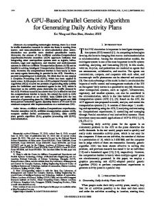
Fig. 1. (a) Workspace movement for the conventional GTD. (b) Workspaces movement for the proposed parallel GTD. An matrix is used as an example. Note that the data pattern of the upper-triangular elements may not be exactly the same as shown here, because the interim results are data-dependent.
Parallel Mode: In the parallel mode, the algorithm performs , resulting in , symmetric permutation on , and are relosuch that the elements , , , and elements cated to the of , respectively. Here, , , , are determined by (9) (10) (11) (12) We define two 2 2 matrices
and
, (13)
which correspond respectively to workspace and workspace of . We can also define as the identity matrix with workspace submatrix replaced by and workspace submatrix by , for . The sub-maand are designed to achieve “bottom-up” and trices “top-down” transformation, given by
where
, and , , . With the aforementioned
construction, we have
(14) (15) , where and . Here we use to represent the “don't-care” terms. The algorithm then sets , , and , leaves the parallel mode, and proceeds to the next iteration. The algorithm stops where . Bottom-up Mode: It is noted that, in some situations, “bottom-up” and “top-down” transformation cannot be performed simultaneously, and hence parallel mode cannot be used. For example, when is even, there are workspaces in total (which is an odd number) and hence there will always be one iteration, which can be chosen between “bottom-up” and “top-down” transformations, but not both. When one of the indices from and is duplicated with one of the indices from and , parallel mode can also not be used. In those cases, simply perform a “bottom-up” transformation which results in the bottom-up mode. Mathematically, the operations required in the bottom-up mode are identical to those required in the parallel mode, except that the operations with subscript will be ignored. After all the operations have been performed, the algorithm sets and , leaves the bottom-up mode and proceeds to the next iteration. The algorithm stops if . By the end of the algorithm, we obtain the GTD expression in terms of the component matrices , , where is the , and number of iterations required in the algorithm, which generally depends on the channel realization and the pre-specified can be achieved. The vector . In the best case, simulation result for matrix sizes from 2 2 to 10 10 is shown in and
1102
IEEE TRANSACTIONS ON CIRCUITS AND SYSTEMS—I: REGULAR PAPERS, VOL. 62, NO. 4, APRIL 2015
Fig. 2. Comparison of computational complexity between the sequential algorithm and the proposed parallel GTD algorithms.
Fig. 2. Since the performance of the parallel algorithm depends on the matrix condition, random matrices are tested for each size. From simulation, the proposed parallel GTD yields a 1.66 speedup for an 8 8 matrix. The processing speed roughly doubles when the matrix size approaches infinity. IV. ARCHITECTURE DESIGN A. CORDIC-Based Systolic-Array Architecture CORDIC is adopted as the basic computation unit because of its low hardware complexity and diverse functionality [26]–[28]. The general function of CORDIC can be described as
(16) where indicates the rotation direction and controls the CORDIC for three (circular, linear, and hyperbolic) coordinate systems. The CORDIC is area-efficient for implementing the key Givens rotation and arithmetic functions required in the proposed parallel GTD algorithm. Fig. 3(a) shows the systolic array architecture of the proposed GTD processor. To support a matrix up to 8 8 in size, 4 diagonal cores and 12 off-diagonal cores are deployed in a 4 4 systolic array. One diagonal/off-diagonal core is used for 2 2 matrix transformation. The diagonal core is composed of 2 master CORDICs and 2 slave CORDICs, and the off-diagonal core 4 slave CORDICs. To complete Givens rotations for SVD and GTD, the master CORDICs in the diagonal cores calculate the required rotation angles and transmit the rotation information (encoded in the rotation direction ) to the off-diagonal cores in the same column (row), according to right (left) rotation; the slave CORDICs in the diagonal and off-diagonal cores in the same column (row) rotate accordingly. The master and slave cores are so tailored as to support the required operations with minimum hardware complexity. The details of the master and slave CORDICs are shown in Fig. 3(a). For a master CORDIC, the circular-vectoring mode is required to find the required rotation angles and to nullify a specific element. The circular-rotation mode is used to rotate angles. Additionally, the hyperbolic-vectoring mode is required for function for GTD. To this end, a 1-bit XOR is added for the control of adder/subtracter to realize the function of , the control signal for different coordinate systems in the CORDIC [26]. A slave CORDIC has two shifters and two add-subtracters in a
Fig. 3. (a) The systolic array for SVD-based GTD, where and denote didenotes a master (slave) agonal core and off-diagonal core, respectively; CORDIC. (b) The details of the master and slave CORDICs; N denotes the data word length.
typical CORDIC structure to rotate the input vector the designated angle sent from a master CORDIC.
by
B. Complex-Valued SVD SVD is the pre-processing of the GTD and can be realized through a systolic array, as shown in Fig. 3(a), using the Jacobi method [31]. In the Jacobi method, an arbitrary unitary transformation is accomplished by several successive Givens rotations, and can be applied to unitary matrices and in SVD, and and in GTD. The complex-valued SVD algorithm is adopted here, instead of the equivalent real-valued SVD algorithm [25], [29], [30], because the outputs of the real-valued SVD are not well ordered for the GTD, and also consume larger area. By leveraging the characteristic of the Givens rotation, multiple independent Givens rotations can be performed in parallel to improve computational efficiency. For instance, an 8 8 matrix can be assigned to 4 independent processing cores, each for a 2 2 submatrix. To facilitate further discussion, we define
where and are angle parameters within . The key transformation for every 2 2 complex submatrix can then be described as follows (see [31] for detail). Step 1: Nullify the imaginary part of the second row:
YANG et al.: A SYSTOLIC ARRAY BASED GTD PROCESSOR WITH A PARALLEL ALGORITHM
1103
Fig. 4. Detailed steps (including element changes and dataflow) for SVD in the proposed systolic-array architecture.
This step can be completed by the CORDICs in the circularvectoring mode against the imaginary parts. Step 2: Nullify the element (2, 1):
where . This step can be completed by the CORDICs in the circular-vectoring mode against the real part. Step 3: Nullify the imaginary part of all elements:
where , . Step 3 can be accomplished by 3 CORDIC operations: 1) A circular-vectoring mode is applied to determine the two required angles ( and ). 2) A circular-rotation mode is applied to rotate the vectors by the specific angles ( and ). 3) A circular-vectoring mode is applied to nullify the imaginary part of the elements and . This operation is equivalent to rotating the vectors by and in the circular-rotation mode. With Steps 3-2 and 3-3, the element (2,2) is equivalently rotated by , which is equal to zero; so, the imaginary part of the element (2,2) is also nullified. Step 4: Diagonalize the matrix:
, and . Step 4 is performed in a manner similar to that described in Step 3, excepting that only the real part needs to be nullified, because all the elements are now real. where
Fig. 5. Efficient CORDIC implementation for top-down transformation. HYP, CIR, and VEC denote hyperbolic, circular, and vectoring modes, respectively. The slave CORDICs are in the rotation mode.
1) A circular-vectoring mode is applied to determine the two and ). is found accordrequired angles ( ingly by taking the average of the two angles. 2) A circular-rotation mode is applied to rotate the vectors by . 3) A circular-vectoring mode is applied to nullify the element . This operation is equivalent to rotating the vectors by in the circular-rotation mode. The element (2,1) is also nullified, because the transformations described in Steps 4-2 and 4-3 are equivalent to rotating and , respectively, which are asthe matrix by signed for matrix diagonalization.
1104
IEEE TRANSACTIONS ON CIRCUITS AND SYSTEMS—I: REGULAR PAPERS, VOL. 62, NO. 4, APRIL 2015
Fig. 6. Detailed steps (including element changes and dataflow) for GTD in the proposed systolic-array architecture.
The foregoing steps are carried out by changing the control mode and the input of each CORDIC. Overall, 8 CORDIC operations are required for an elementary 2 2 SVD. If each off-diagonal element is nullified once, then the so-called sweep is completed. The dataflow of the systolic array and the corresponding operations for SVD are illustrated in Fig. 4. Note that the required operations can be realized efficiently by deploying the CORDICs in the diagonal cores. To nullify all the off-diagonal elements, the matrix elements in the systolic array are cyclically shifted in the next sweep with proper scheduling. The scheduling of cyclic shift can be found in [32]. After sweeps, the matrix elements return to the original locations. The sweeps are conducted iteratively to sweeps suffice. approach a diagonal matrix; usually, All cores are executed in parallel to improve the computation speed, as shown in Fig. 4.
shown in Fig. 5. The bottom-down GTD can be realized in a similar fashion. The three steps required for this operation are described below. Step 1: Two functions can be realized in parallel by the hyperbolic-vectoring mode CORDIC. Step 2: The results of Step 1 are used as the input for master CORDIC in the diagonal core, and the CORDIC operates in the circular-vectoring mode to execute arctan function. Meanwhile, the master CORDIC transmits rotation directions to the slave CORDICs, so that slave CORDICs can operate in the circularrotation mode to realize . Step 3: The key 2 2 transformation, given by
C. SVD-Based GTD and GMD
can also be efficiently realized by CORDICs. The matrix multiplication is performed by nullifying the element (2,1) in a circular-vectoring mode of the master CORDIC. The slave CORDIC follows the rotation direction, transmitted from the master CORDIC. After completion of vectoring, a top-down GTD is completed. The proposed CORDIC-based solution has 25 lower hardware complexity, as compared to that realized by direct-mapped implementation. Here, a low-complexity Newton-Ralphson algorithm based divider [35] is used for comparison. Also, the proposed method is resilient against truncation errors introduced by multiplication and division, and thus improves numerical accuracy. The dataflow and the corresponding operations required for the proposed GTD algorithm are illustrated in Fig. 6. As shown in Fig. 2(b), the bottom-up and the top-down GTDs can be executed simultaneously in Step 2. In contrast, Step 3 and Step 4 are realized sequentially. The proposed GTD processor can implement GMD by substituting the geometric mean of the singular values into the user-specific vector .
The outputs of SVD are stored in the registers to perform the succeeding GTD. The arithmetic units can be shared, because Givens rotations and top-down/bottom-up transformations can also be computed efficiently through the systolic array architecture by employing CORDICs. Multiplexers are added to switch data between different workspaces. Owing to inherent data dependence of GTD, the transformations (14) and (15) cannot be executed in parallel. In this work, parallel processing of the transformations (14) and (15) can be done by taking advantage of the characteristic whose lower-triangular elements are all zero. Computation of and (20)–(23) is a complex exercise. Especially, direct mapping of (20) needs four multiplications and two divisions with high precision for either or . In this work, we therefore propose a CORDIC-based solution to reduce the complexity of computation (20)–(23), and to maximize hardware utilization. Although implementation of functions and , by directly using CORDICs, seems infeasible, it actually can be realized efficiently. The CORDIC operations for a 2 2 top-down GTD is
(17)
YANG et al.: A SYSTOLIC ARRAY BASED GTD PROCESSOR WITH A PARALLEL ALGORITHM
1105
Fig. 8. MSE performances for distinct design parameters.
Fig. 9. MSE performance for different matrix sizes. Fig. 7. (a) Architecture flexibility for matrix sizes from 2 2 to 8 8. Gray (white) squares represent active (inactive) cores. Black dots denote valid elements and white dots are set to zero. (b) Scheduling for a 7 7 matrix. SVD for odd matrices is feasible by applying only left (right) rotation to a specific column (row).
of computations. Flexibility for both even and odd matrices for GTD can be easily realized by disabling unused cores as shown in Fig. 7(a). V. EXPERIMENTAL VERIFICATION
D. Scalability and Flexibility A scalable and flexible architecture is developed for arbitrarysized SVD and GTD. Custom instructions are used to assign the operation mode and the input of CORDICs for each diagonal/ off-diagonal core. To support an arbitrary-sized matrix, inactive cores are disabled and the workspaces starting from both the upper-left and lower-right cores are properly set. As shown in Fig. 7(a), if the core contains valid elements, it is activated. For example, computations start from workspaces 1 and 4 for a 5 5 matrix. The unused cores are disabled and the registers within these cores set to zero. The flexibility for supporting both even and odd matrices for SVD is realized by padding zeros and activating specific cores. For even matrices, the active cores (with valid elements) are executed in the same manner as that for the full-sized matrix; the inactive cores are disabled. The operation of cyclic shift is bounded by the active cores; so, the elements in the inactive cores will not be shifted. For odd matrices, zeros are padded to form an even matrix first. The cores are disabled sequentially along the diagonal direction, back and forth. The zeros are switched according to the order of cyclic shift. Only left (right) rotation to a specific column (row) is applied to maintain the correct functionality. The scheduling for a 7 7 matrix is described in Fig. 7(b). After 7 sweeps, the required computations for SVD are applied to all the valid elements. This scheduling ensures that each element is performed with the same number
This section presents the implementation result and performance evaluation of the proposed GTD architecture. The latency constraint of 16 specified in the 802.11ac standard [33] is used as design specification. A. System Parameters The mean square error (MSE), given by is used for numerical performance evaluation. Wordlength and number of CORDIC iterations are used as tuning parameters. The results are shown in Fig. 8. Ideally, the MSE performance of the functions realized by CORDICs improves gradually as the number of CORDIC iterations increases. However, it may not be always true if the implementation is with finite wordlength, as shown in Fig. 8, because the accuracy of a small number saturates easily after bit-shift operation in the 2's complement arithmetic. The numerical error propagates in the iterative loop and this happens more frequently when the wordlength becomes smaller. From simulation, a 15-bit datapath with 10 iterations suffices to achieve the least MSE bound. The wordlength of the datapath and the number of iterations can be reduced if a lower MSE requirement is set. Simulations over 10k MIMO channels with Rayleigh fading are conducted. The MSE performance of the proposed GTD processor is shown in Fig. 9. The MSE of the 2 2 matrix is lower than that of the other matrix sizes, because it suffers from less
1106
IEEE TRANSACTIONS ON CIRCUITS AND SYSTEMS—I: REGULAR PAPERS, VOL. 62, NO. 4, APRIL 2015
Fig. 10. (a) Comparison for number of cycles between the conventional and the proposed (left and right, respectively, in the pairs) SVD-based GTD implemenfor the 8 8 matrix case. (b) Power consumption for the tations. A 44–51% cycle reduction is achieved for the supported matrix sizes. The latency is set to 12 supported matrix sizes. The clock frequency for 2 2–7 7 matrices can be scaled down accordingly to achieve the latency of 12 .
error propagation than the other matrices do. The latency breakdown for supported matrix sizes is shown in Fig. 10(a). Compared to the conventional GTD implementation, a latency reduction of 44–51% is achieved. The overall latency is dominated by the SVD owing to efficient implementation of the proposed parallel GTD. The minimum operating frequency is determined by the maximum latency of the proposed GTD scheme. As regards the 8 8 case, it takes 1342 cycles, which requires the minimum operating frequency of 84 MHz for the 16 latency constraint specified in the 802.11ac standard. B. Chip Implementation The proposed GTD processor integrates 378k gates in based on standard 90 nm CMOS process. The chip layout and summary are shown in Fig. 11 and Table I. The maximum operating frequency is 112.4 MHz, which offers capability against PVT variations and/or for a shorter latency requirement. Under maximum operating frequency, the proposed design can finish a matrix within 12 . For smaller-sized matrices, the power consumption can be reduced through frequency scaling due to reduced processing latency. Power consumption for different supported matrix sizes is shown in Fig. 10(b). The proposed GTD processor dissipates 15.9–172.7 mW for 2 2–8 8 matrices from a 1.0 V supply. Further power reduction is possible if voltage scaling is allowed. To the best of our knowledge, this work is the first GTD implementation in the published literature. To demonstrate the performance, prior SVD and GMD designs are used to make a comparison, considering that both SVD and GMD can be used for MIMO precoding. Table II shows the features of the chips. In [22], a GMD processor with an efficient parallel algorithm is proposed for 4 4 GMD. Design [35] implements adaptive SVD by blind-tracking of least mean square (LMS) algorithm for 4 4 MIMO systems. Design [36] is a SVD processor for matrix sizes from 2 2 to 4 4. It improves the algorithm of [35] by reducing the convergence time. The proposed design is flexible to support SVD, GTD, and GMD for matrix sizes from 2 2 to 8 8, in addition to the trivial 1 1 case with even less gate count. To make a fairer comparison, power and throughput performance
Fig. 11. Chip layout of the proposed GTD processor. TABLE I CHIP SUMMARY
SVD, for 4 4 SVD and GTD/GMD is listed separately. For this work has a compromised performance between [35] and [36] in terms of power and throughput. For GMD, [22], , achieves which is dedicated for matrices of dimension a high throughput, while our proposed GTD algorithm does not have such dimensionality constraint and hence is more general. Given the fact that GTD is more general and more powerful than GMD, it is not surprising that a well-designed specialized GMD
YANG et al.: A SYSTOLIC ARRAY BASED GTD PROCESSOR WITH A PARALLEL ALGORITHM
TABLE II PERFORMANCE COMPARISON
The unit of throughput is “(Matrices/s).” Note that the clock frequency of this work for these operation modes is set to 112.4 MHz here.
processor can have higher throughput than a more general GTD processor. VI. CONCLUSION In this paper, we have presented a flexible processor for processing 1 1 to 8 8 SVD, GTD, and GMD. A parallel GTD algorithm that processes both upper-left and lower-end corners simultaneously is proposed. The algorithm supports up to 1.66 higher speed than does the conventional algorithm for a 8 8 matrix. A systolic array is adopted to facilitate Givens rotation. The systolic-array architecture allows for multi-operation for SVD and GTD by reconfiguring the datapath. CORDICs are used as basic arithmetic units to support versatile functions with high area efficiency. Four CORDICs are clustered for diagonal/off-diagonal cores. The diagonal core finds the rotation angle and the related off-diagonal core rotate accordingly by the received rotation directions. Distinct matrix sizes are supported by appropriate disabling of inactive cores. The critical 2 2 top-down/bottom-up GTD transformations can be efficiently implemented by the proposed CORDIC solution, reducing the hardware complexity by 25 , as compared to the complexity of the direct-mapped implementation. The proposed GTD processor integrates 378 k logic gates in 1.96 . It dissipates 172.7 mW at 112.4 MHz for a 8 8 GTD. REFERENCES [1] R. A. Horn and C. R. Johnson, Matrix Analysis. New York: Cambridge Univ. Press, 1985. [2] G. H. Golub and C. F. V. Loan, Matrix Computations, 3rd ed. Baltimore, MD, USA: Johns Hopkins Univ. Press, 1996. [3] Y. Jiang, W. W. Hager, and J. Li, “The geometric mean decomposition,” Linear Algebra Its Appl., vol. 396, pp. 373–384, Feb. 2005. [4] J.-K. Zhang, A. Kavčić, and K. M. Wong, “Equal-diagonal QR decomposition and its application to precoder design for successive-cancellation detection,” IEEE Trans. Inf. Theory, vol. 51, no. 1, pp. 154–172, Jan. 2005. [5] Y. Jiang, J. Li, and W. W. Hager, “Joint transceiver design for MIMO communications using geometric mean decomposition,” IEEE Trans. Signal Process., vol. 53, no. 10, pp. 3791–3803, Oct. 2005.
1107
[6] S. Lin, W. W. L. Ho, and Y.-C. Liang, “Block diagonal geometric mean decomposition (BD-GMD) for MIMO broadcast channels,” IEEE Trans. Wireless Commun., vol. 7, no. 7, pp. 2778–2789, Jul. 2008. [7] E. C. Y. Peh and Y. C. Liang, “Power and modulo loss tradeoff with expanded soft demapper for LDPC coded GMD-THP MIMO systems,” IEEE Trans. Wireless Commun., vol. 8, pp. 714–724, Feb. 2009. [8] F. Liu, L. Jiang, and C. He, “Advanced joint transceiver design for block diagonal geometric mean decomposition based multiuser MIMO system,” IEEE Trans. Veh. Technol., vol. 59, pp. 692–703, Feb. 2010. [9] C.-H. Liu and P. P. Vaidyanathan, “Generalized geometric mean decomposition and DFE transceiver design—Part I: Design and complexity,” IEEE Trans. Signal Process., vol. 60, no. 6, pp. 3112–3123, Jun. 2012. [10] C.-H. Liu and P. P. Vaidyanathan, “Generalized geometric mean decomposition and DFE transceiver design—Part II: Performance analysis,” IEEE Trans. Signal Process., vol. 60, no. 6, pp. 3124–3133, Jun. 2012. [11] M. Tomlinson, “New automatic equalizer employing modulo arithmetic,” Electron. Lett., vol. 7, pp. 138–139, Mar. 1971. [12] H. Harashima and H. Miyakawa, “Matched-transmission technique for channels with inter-symbol interference,” IEEE Trans. Commun., vol. 20, no. 4, pp. 774–780, Aug. 1972. [13] Y. Jiang, W. W. Hager, and J. Li, “The generalized triangular decomposition,” Math. Comput., vol. 77, pp. 1037–1056, Oct. 2008. [14] H. Weyl, “Inequalities between two kinds of eigenvalues of a linear transformation,” Proc. Natl. Acad. Sci. USA, vol. 35, no. 7, pp. 408–411, 1949. [15] A. W. Marshall and I. Olkin, Inequalities: Theory of Majorization and Its Applications. New York: Academic, 1991. [16] Y. Jiang, J. Li, and W. W. Hager, “Transceiver design using generalized triangular decomposition for MIMO communications with QoS constraints,” in Proc. 38th Asilomar Conf. Signals, Syst., Comput., Nov. 2004, vol. 1, pp. 1154–1157. [17] Y. Jiang, W. W. Hager, and J. Li, “Tunable channel decomposition for MIMO communiations using channel state information,” IEEE Trans. Signal Process., vol. 54, no. 11, pp. 4405–4418, Nov. 2006. [18] C.-C. Weng, C.-Y. Chen, and P. P. Vaidyanathan, “MIMO transceivers with decision feedback and bit loading: Theory and optimization,” IEEE Trans. Signal Process., vol. 58, no. 3, pp. 1334–1346, Mar. 2010. [19] C.-H. Liu and P. P. Vaidyanathan, “Zero-forcing DFE transceiver design over slowly time-varying MIMO channels using ST-GTD,” IEEE Trans. Signal Process., vol. 58, no. 11, pp. 5779–5790, Nov. 2010. [20] C.-H. Liu and P. P. Vaidyanathan, “MMSE DFE transceiver design over slowly time-varying MIMO hannels using ST-GTD,” IEEE Trans. Signal Process., vol. 59, no. 1, pp. 277–289, Jan. 2011. [21] W.-D. Chen and Y.-T. Hwang, “A constant throughput geometric mean decomposition scheme design for wireless MIMO precoding,” IEEE Trans. Veh. Tech., vol. 62, no. 5, pp. 2080–2090, Jun. 2013. [22] Y.-T. Hwang, W.-D. Chen, and C.-R. Hong, “A low complexity geometric mean decomposition computing scheme and its high throughput VLSI implementation,” IEEE Trans. Circuits Syst. I, Reg. Papers, vol. 61, no. 4, pp. 1170–1182, Apr. 2014. [23] C.-E. Chen, Y.-C. Tsai, and C.-H. Yang, “An iterative geometric mean decomposition algorithm for MIMO communications systems,” IEEE Trans. Wireless Commun., vol. 14, no. 1, pp. 343–352, Jan. 2015. [24] W. C. Kan and G. E. Sobelman, “MIMO transceiver design based on a modified geometric mean decomposition,” in Proc. IEEE Int. Symp. Circuits Syst., May 2007, pp. 677–680. [25] R. P. Brent, F. T. Luk, and C. V. Loan, “Computation of the singular value decomposition using mesh connected processors,” J. VLSI Comput. Syst., vol. 1, no. 3, pp. 242–270, Mar. 1982. [26] P. K. Meher, J. Valls, T.-B. Juang, K. Sridharan, and K. Maharatna, “50 years of CORDIC: Algorithms, architectures, applications,” IEEE Trans. Circuits Syst. I, Reg. Papers, vol. 56, pp. 1893–1907, Sep. 2009. [27] J. Volder, “The CORDIC trigonometric computing technique,” IRE Trans. Elect. Comp., vol. EC-8, pp. 330–334, Sep. 1959. [28] J. S. Walther, “A unified algorithm for elementary functions,” in Proc. Spring Joint Comput. Conf., May 1971, pp. 379–385. [29] J. R. Cavallaro and F. T. Luk, “CORDIC arithmetic for an SVD processor,” J. Parallel Distrib. Comput., vol. 5, pp. 271–290, Jun. 1988. [30] A. Ahemdsaid, A. Amira, and A. Bouridane, “Improved SVD systolic array and implementation on FPGA,” in Proc. IEEE Int. Conf. FieldProgrammable Technol. (FPT), Dec. 2003, pp. 35–42. [31] N. D. Hemkumar and J. R. Cavallaro, “A systolic VLSI architecture for complex SVD,” in Proc. IEEE Int. Symp. Circuits Syst. (ISCAS), May 1992, vol. 3, pp. 1061–1064.
1108
IEEE TRANSACTIONS ON CIRCUITS AND SYSTEMS—I: REGULAR PAPERS, VOL. 62, NO. 4, APRIL 2015
[32] R. P. Brent and F. T. Luk, “The solution of singular-value and symmetric eigenvalue problems on multiprocessor arrays,” Siam J. Sci. Stat. Comput, vol. 6, no. 1, pp. 69–84, Jan. 1985. [33] IEEE Standard Draft 5.0, IEEE 802.11ac, 2013. [34] C.-S. Hsu, “Geometric Mean Decomposition Aided Tomlinson-Harashima Precoding for Iterative MIMO Systems,” M.S. thesis, National Chung Cheng University, Chiayi, Taiwan, 2013. [35] D. Markovic, B. Nikolic, and R. W. Brodersen, “Power and area minimization for multidimensional signal processing,” IEEE J. Solid-State Circuits, vol. 42, no. 4, pp. 922–934, Apr. 2007. [36] Y.-L. Chen, C.-Z. Zhan, T.-J. Jheng, and A.-Y. Wu, “Reconfigurable adaptive singular value decomposition engine design for high-throughput MIMO-OFDM systems,” IEEE Trans. Very Large Scale Integr. (VLSI) Syst., vol. 21, no. 4, pp. 747–760, Apr. 2013. Chia-Hsiang Yang (S'07-M'10) received his B.S. and M.S. degrees in electrical engineering from the National Taiwan University, Taiwan, in 2002 and 2004, respectively. He received his Ph.D. degree from the Department of Electrical Engineering of the University of California, Los Angeles, CA, USA, in 2010. He then joined the faculty of the Electronics Engineering Department at the National Chiao Tung University, Taiwan, where he is currently an Associate Professor. His research interests are in energy-efficient integrated circuits and architectures for biomedical and communication signal processing.
Chun-Wei Chou received his B.S. degree from the Department of Electrical Engineering, National Chung Hsing University, Taichung, Taiwan. He is currently pursuing M.S. degree in electronics engineering from National Chiao Tung University, Hsinchu, Taiwan. His research interests include algorithms, development of signal processing, and VLSI design for wireless baseband processing.
Chia-Shen Hsu was born in Taichung, Taiwan. He received his B.Sc. degree from Feng-Chia University, Taiwan, in 2011 and the M.Sc. degree from National Chung Cheng University, Taiwan, in 2013, respectively. His research interests include signal processing and multiple-input-multiple-output (MIMO) communications.
Chiao-En Chen (M'05) was born in Kaohsiung, Taiwan, in 1976. He received his B.Sc. and M.Sc. degrees in electrical engineering from National Taiwan University, Taipei, in 1998 and 2000 respectively. From 2003 to 2008, he was with the Electrical Engineering Department at University of California, Los Angeles, where he received his Ph.D. degree. Since 2008, he has been working at both the Department of Electrical Engineering and the Department of Communications Engineering at National Chung Cheng University, Chiayi, Taiwan, where he is currently an Associate Professor. His research interests include array signal processing, detection and estimation theory, and multiple-input-multiple-output (MIMO) communications. Dr. Chen was a co-recipient of the Best Paper Award in IEEE WCNC 2012, and a coauthor of the book Detection and Estimation for Communication and Radar Systems (Cambridge University Press, 2013).