frame frequencies of 15 and 150 frames/s, respectively. Index TermsâCMOS ... Thus, the SA-ADC in [9] requires an additional correlated dou- ble sampling ...
IEEE TRANSACTIONS ON ELECTRON DEVICES, VOL. 59, NO. 6, JUNE 2012
1693
A 1.92-Megapixel CMOS Image Sensor With Column-Parallel Low-Power and Area-Efficient SA-ADCs Min-Seok Shin, Student Member, IEEE, Jong-Boo Kim, Student Member, IEEE, Min-Kyu Kim, Student Member, IEEE, Yun-Rae Jo, and Oh-Kyong Kwon, Member, IEEE
Abstract—This paper presents a CMOS image sensor with 10-bit column-parallel successive approximation analog-to-digital converters (SA-ADCs). The SA-ADC in each column integrates the binary-weighted references instead of using an internal digital-to-analog converter (DAC) to reduce the area. The area of the column 10-bit SA-ADC is 9 μm × 425 μm. The area of the capacitor array in the SA-ADC is reduced to only 2.8% compared with that of a conventional binary-weighted capacitor DAC. In order to reduce the power consumption, the SA-ADC uses the switched power technique. The constant analog-to-digital conversion time and the switched power technique increase the power saving rate as the frame rate decreases. The proposed image sensor has been fabricated using a 0.13-μm CMOS process. The measured power consumption of the proposed SA-ADC is reduced to 85% and 58% of that in the SA-ADC without the switched power technique at the frame frequencies of 15 and 150 frames/s, respectively. Index Terms—CMOS image sensor, column-parallel readout architecture, low-power consumption, small-area successive approximation analog-to-digital converter (SA-ADC).
I. I NTRODUCTION
A
S RECENTLY introduced mobile devices such as smartphones require high-resolution and high-speed image sensors over a high-definition (HD) 720p (1280 × 720 pixels) system with a frame rate of 60 frames/s, the high-speed readout of CMOS image sensors has become an important performance factor in mobile applications. The power consumption of a CMOS image sensor is also one of the key specifications in portable applications. The column-parallel readout architecture of CMOS image sensors has been widely used for mobile applications because it has advantages of low-power consumption and high-speed operation [1]–[8]. Characteristics of CMOS image sensors with column-parallel readout architecture are influenced by the type of analog-to-digital converter (ADC) used. Single-slope ADCs (SS-ADCs) have been adopted in most column-parallel CMOS image sensors due to their good linearity and relatively low-power characteristics [1]–[3]. Manuscript received November 3, 2011; revised February 18, 2012 and February 29, 2012; accepted February 29, 2012. Date of publication April 4, 2012; date of current version May 23, 2012. This work was supported in part by the Image Frontier Center and in part by Samsung Electronics Co., Ltd. for IC fabrication. The review of this paper was arranged by Editor J. R. Tower. The authors are with the Department of Electronics and Computer Engineering, Hanyang University, Seoul 133-791, Korea (e-mail: okwon@ hanyang.ac.kr). Digital Object Identifier 10.1109/TED.2012.2190936
However, SS-ADCs require a very fast clock speed and have high power consumption for high-speed CMOS image sensors [3]. In order to develop a CMOS image sensor with a high frame rate and low-power characteristics, several columnparallel ADCs have been studied [4]–[8]. Successive approximation ADCs (SA-ADCs) [4], [5] and cyclic ADCs [6]–[8] are appropriate for high-speed operation because they can resolve one bit per single clock cycle. However, SA-ADCs have an area problem because of the binary-weighted capacitor array, and cyclic ADCs have a power consumption problem because they use a high-gain amplifier per column. The SA-ADC using scaled reference voltages was reported to reduce the area of ADCs [5]. However, the size of the capacitor array digital-to-analog converter (DAC) is still too large to be applied to fine pixel pitches. Although the SA-ADC using a binary-weighted reference voltage has been proposed in [9] to reduce the area of the capacitor array, this solution is not suitable for CMOS imager applications because it does not have the function to cancel the reset noise from the pixel circuit. Thus, the SA-ADC in [9] requires an additional correlated double sampling (CDS) circuit, and thereby, it consumes additional area and power. The cyclic ADC adopting an additional CDS amplifier for low supply operation was introduced to reduce the power consumption [8]. The analog-to-digital conversion time of the cyclic ADC in [8], which is only 0.5 μs, is relatively shorter than the CDS time of 2.9 μs. Although the cyclic ADC does not use in the CDS operation, the static power of the cyclic ADC is still consumed. Accordingly, the column ADC can reduce the static power consumption using the power-down scheme during the CDS operation. In order to simultaneously reduce the area and the power consumption of column-parallel ADCs, we propose a lowpower and area-efficient column-parallel SA-ADC in this paper. The ADC employs the switched capacitor circuit to reduce the area and the switched power technique to reduce the static power consumption. To verify the high-speed and low-power operation, we designed and fabricated the CMOS image sensor adopting the proposed SA-ADCs and the low-power technique using a 0.13-μm CMOS process. In Section II of this paper, we introduce the block diagram of the CMOS image sensor, the architecture of the proposed SAADC, and the low-power technique. Section III describes the circuit implementation of the proposed ADC and the reference voltage generator. The experimental results of the chip are
0018-9383/$31.00 © 2012 IEEE
1694
IEEE TRANSACTIONS ON ELECTRON DEVICES, VOL. 59, NO. 6, JUNE 2012
Fig. 1. Block diagram of the image sensor and schematic of the pixel circuit.
analyzed in Section IV. Finally, the conclusions are given in Section V. II. I MAGE S ENSOR A RCHITECTURE A. Block Diagram Fig. 1 shows the block diagram of the image sensor and a schematic of the pixel circuit. Two photodiodes (PDs) share the pixel circuit of two vertically adjacent pixels to reduce the pixel pitch. Because the pixel pitch is only 2.25 μm, it is too narrow to lay out the column-parallel ADC using differential signals. Thus, we adopted the staggered placement of ADCs on the top and bottom of the image sensor to alleviate the design complexity [8]. In our design, the column-parallel ADC has a column pitch of 9 μm. The shift register array stores the digital data resolved by the column ADCs. Two horizontal scanners (H-scanners) and four sense amplifiers are used to transfer the captured image data out of the image sensor. A vertical scanner (V-scanner) supplies the digital signals (ΦRX , ΦTX1 , ΦTX2 , and ΦSX ) for the reset, charge transfer, and row line selection operations to the pixel circuit. A timing generator controls the entire operation of the CMOS image sensor. A bias generator and a binary-weighted reference generator provide the bias currents and reference voltages to the column ADCs. In order to minimize the switching noise effect from the digital circuit, the digital and analog circuitries are separately placed to the left and right sides in the pixel array. B. Area-Efficient Column-Parallel SA-ADC Architecture The proposed SA-ADC is composed of an integrating DAC, a comparator, and a latch, as shown in Fig. 2. The integrating DAC accompanies the CDS operation and the digital-to-analog conversion. During the CDS operation, the integrating DAC
Fig. 2. (a) Block and (b) timing diagrams of the proposed area-efficient SA-ADC.
samples the reset voltage (VRST ) and the signal voltage (VSIG ). When ΦSX and ΦRX are high, the floating diffusion (FD) of the pixel is reset. After ΦRX becomes low, the output voltage of the pixel (VPIX ) is VRST . When ΦTX1(2) is high, photoinduced charges are transferred from the photodiode [PD1(2)] to the FD. After ΦTX1(2) becomes low, VPIX is VSIG . During the analog-to-digital conversion, the integrating DAC accumulates the binary-weighted differential reference voltage (VREFP − VREFN ) and outputs the difference between the accumulated binary-weighted differential reference voltage and the differential input voltage (VRST − VSIG ). The output of the integrating DAC (VOUTP − VOUTN ) is resolved in the comparator. The output of the comparator is stored in the latch and determines whether to add or subtract the halved reference voltage in the next step. The proposed scheme reduces the area of a SA-ADC because it only requires an integrator instead of the binaryweighted capacitor array DAC. The whole column ADCs share the binary-weighted reference voltage. C. Power Reduction Technique The proposed SA-ADC uses an integrator to reduce the area of a DAC, which increases the power consumption. In order to reduce the power consumption, we apply the switched power technique [10] for an integrator consuming high current. Fig. 3 describes the concept of the switched power technique for an image sensor. The integrator in the integrating DAC is disconnected from the power supply during the CDS operation. When a CMOS image sensor has 1200 rows and operates at 120 frames/s, the row line time is 6.94 μs. The CDS operation accounts for 74% of the row line time because the SA-ADC has a conversion time of only 1.78 μs. Accordingly, the switched power technique ideally saves 74% of the power in a column ADC. When the A/D conversion time does not vary with the
SHIN et al.: 1.92-MEGAPIXEL CMOS IMAGE SENSOR WITH COLUMN-PARALLEL SA-ADCs
1695
the initialization of the SA logic circuit; therefore, the first differential output of AINT (VOUT,first ) is given by VOUT,first = VOUTP − VOUTN = VRST − VSIG − (VREFP − VREFN )/2.
Fig. 3. Concept of the switched power technique to reduce power consumption at (a) 120 and (b) 60 frames/s.
The comparator resolves the most significant bit (MSB) from VOUT,first , and the output of the comparator is stored in the latch. The output of the latch determines whether to subtract or add the reference voltages during the next step. During Φ1 , CF retains the output voltage, and the charges of CSR and CSS are fully discharged. At the same time, the offset of AINT is newly stored in COA . These two operations in Φ1 and Φ2 are alternately repeated until the required resolution is obtained. After the analog-to-digital conversion for N bits, the final differential output of AINT (VOUT,final ) can be expressed as VOUT,final = VRST − VSIG − −
(a) Schematic and (b) timing diagram of the proposed SA-ADC.
frame rate, the CDS operation time increases, as shown in Fig. 3. Therefore, the power saving rate increases as the frame rate decreases when applying the switched power technique at various frame rate conditions.
III. C IRCUIT I MPLEMENTATION A. Proposed SA-ADC Fig. 4 shows the schematic and the timing diagram of the proposed SA-ADC. The integrating DAC contains an operational amplifier (AINT ), two sampling capacitors (CSR , CSS ), two feedback capacitors (CF ), two capacitors (COA ) to store the offset voltage of AINT , and several switches. When ΦSR and ΦSS become alternately high, VRST and VSIG of the pixel circuit are sampled to the reset sampling capacitor (CSR ) and the signal sampling capacitor (CSS ), respectively. During this CDS period, charges in CF are fully discharged for initialization. The offset voltage of AINT is stored in COA . After the CDS operation is complete, the differential reference voltages, i.e., VREFP and VREFN , which are reduced to half of the previous voltage level as shown in Fig. 2, are integrated to CF during Φ2 . In the first integration, Φ2,SUB is always high due to
VREFP − VREFN 2
N � Di × 2i × (VREFP − VREFN ) i=2
Fig. 4.
(1)
2N +2
(2)
where Di is the ith digital bit. For example, DN and D1 are the MSB and the least significant bit (LSB), respectively, and Di is determined to be +1 or −1 according to the resolved value from the comparator. The capacitance of the sampling and feedback capacitors is 200 fF to reduce the kT/C noise for 10-bit resolution. The capacitance of COA influences the speed and dc gain of the integrator because its differential input voltage decreases as the capacitance ratio between the input capacitor of AINT and COA increases. Considering the capacitance change from temperature and process variation, COA is designed to be 300 fF. The absolute capacitance value of COA does not affect the nonlinearity errors of the SA-ADC. However, the capacitance mismatches between the sampling and feedback capacitors cause the gain error of the SA-ADC. During the 10bit analog-to-digital conversion, the error from the capacitance mismatches is accumulated ten times in the output voltage of AINT . If the capacitance mismatches between the sampling and feedback capacitors are 0.1%, the maximum value of the accumulated gain error is 1.0 LSB in 10-bit resolution. As a result, the careful layout is required to reduce the capacitance mismatches to less than 0.1%. B. Switched Power Amplifier A schematic of AINT in the integrating DAC is shown in Fig. 5. For implementation in a fine column pitch, the sizes of the transistors should be small. Therefore, AINT has a large offset voltage. A rail-to-rail input stage is used to cover the common-mode input voltage that varies with the offset voltage of AINT . In order to obtain high gain and reduce the area, AINT uses a folded-cascode structure with gain-boosting amplifiers instead of a two-stage structure requiring a frequency compensation capacitor. The dynamic common-mode feedback (CMFB) circuit is used to sustain the output common-mode voltage [11]. AINT also has several power-down switches to
1696
IEEE TRANSACTIONS ON ELECTRON DEVICES, VOL. 59, NO. 6, JUNE 2012
Fig. 6.
Schematic of a comparator in the SA-ADC.
Fig. 5. Schematic of an operational amplifier in the integrator (AINT ).
reduce the power consumption. All of the current paths of AINT are disconnected from the supply voltage during the CDS period according to the ΦPD signal, as shown in Fig. 4. The ADC has 10-bit resolution for the input range of 0.9 V and operates at 7 MHz. The dc gain and bandwidth of an operational amplifier are 85 dB and 30 MHz, respectively, to consider the voltage divide according to the series connection of COA and the input capacitor. The operational amplifier consumes 40 μA. C. Clocked Comparator The input offset voltage of the comparator becomes the offset of the SA-ADC. The photoinduced signal voltage of the pixel is converted to the digital code through the SA-ADC in each column. Although pixels on different column lines generate the same output voltage level, the digital code is varied with the offset of the SA-ADC, and thereby, the column fixed pattern noise (CFPN) occurs. In order to eliminate the input offset voltage of the comparator, the auto-zeroing technique is usually used in a SA-ADC [12]. However, several capacitors and preamplifiers increase the area and power consumption for column SA-ADCs. We used a small-area comparator not using the onchip offset compensation to reduce the area and power consumption of the column SA-ADC. The different offset among column SA-ADCs is compensated using the off-chip signal processing. The clocked comparator is employed to ensure a small area, as shown in Fig. 6. The CFPN due to the difference in electrical characteristics between two input transistors (M1 , M2 ) is calibrated using the measurement-based column offset map. When Φ1b is low, the outputs of the comparator (VCOUTP − VCOUTN ) and the drain node of the input transistors (V1 , V2 ) are reset to the supply voltage (VDDA ). When Φ1b is high, the output of the comparator is determined according to the voltage difference of the differential input (VCINP − VCINN ). In order to reduce the kick-back effect, the comparator uses a static bias current of 5 μA. D. Binary-Weighted Reference Generator The proposed SA-ADC requires the reference voltage that is continuously reduced by a half. A conventional binary-
Fig. 7. (a) Schematic and (b) timing diagram of the proposed binary-weighted reference generator.
weighted reference generator using the cyclic DAC can generate the binary-weighted reference voltage [13]. However, the output voltage of the cyclic DAC becomes zero during a half clock cycle because an amplifier in the cyclic DAC is reset. By that means, the cyclic DAC consumes large power because it drives large capacitive load equivalent to sampling capacitors in all column ADCs. Accordingly, the binary-weighted reference voltage generator, which keeps the output voltage during one clock cycle, is required to reduce power consumption. The binary-weighted reference generator is designed using a switched capacitor circuit, as shown in Fig. 7. The proposed reference generator uses charge sharing to halve the differential reference voltage. In order to further reduce the power consumption, the power-down scheme is also applied to the amplifier in the binary-weighted reference generator. When ΦREFRST and ΦREF1 are high, the offset voltage of the amplifier is stored in CO , and the capacitor (CCS ) for sharing charge and the feedback capacitor (CF ) are initialized. When ΦREFS and ΦREF2 are high, the differential reference
SHIN et al.: 1.92-MEGAPIXEL CMOS IMAGE SENSOR WITH COLUMN-PARALLEL SA-ADCs
1697
Fig. 8. Schematic of the amplifier for the binary-weighted reference generator.
input (VREFP_IN − VREFN_IN ) is transferred to the binaryweighted differential output because CCS and CF have the same capacitance. The voltage difference between VREFP_IN and VREFN_IN is the input range of the ADC. After that, only the charge in CCS is discharged, and the offset voltage of the amplifier is newly stored in CO when ΦREF1 is high. When ΦREF2 and ΦREFCS are high, the charges of CCS and CF are shared, and the output of the amplifier is divided in half. The output of the amplifier is applied to all column SA-ADCs. The discharge of CCS and the charge sharing between CCS and CF are repeated to continuously halve the output reference voltage. All of the capacitors are 5 pF to enhance the matching properties and to reduce the switching error.
Fig. 9. Chip microphotograph.
E. Amplifier for Reference Generator The schematic of the amplifier for the reference generator is shown in Fig. 8. The total load capacitance of the reference generator is 320 pF because it drives 1600 column ADCs with the CSR and CSS of 200 fF during the integration period shown in Fig. 4. In order to reduce the static current and to drive a large capacitive load, the amplifier employs a class-AB output stage. When ΦPD is high, the output transistors of the amplifier are turned off by turning on the transistors, i.e., M1 to M4 . The dc gain and bandwidth of the operational amplifier are 83 dB and 30 MHz, respectively, and the amplifier consumes a static current of 3.4 mA. IV. E XPERIMENTAL R ESULTS The chip microphotograph of the image sensor is shown in Fig. 9. The test chip was fabricated using a 0.13-μm 1-poly 4-metal CMOS process. The column ADC area is 9 μm × 425 μm, and the total column ADC array including the power ring is 3750 μm × 890 μm. The chip die area is 5 mm × 7 mm. The captured raw images have a large CFPN because the input voltage offset of the comparator in the SA-ADC was not compensated to reduce the area consumption. Thus, a calibration method using the measurement-based offset map was implemented to compensate the CFPN. We extracted the column offset map using several captured images at low light intensity. The captured images before and after turning on the calibration function are shown in Fig. 10. In order to verify
Fig. 10. Captured raw images at (a) 20 and (b) 80 lx, and CFPN compensated images at (c) 20 and (d) 80 lx.
that the CFPN originates only from the comparator offset, we applied the calibration function to the image sensor at different light intensities. The measured results show that the major cause of the CFPN is the ADC offset due to the comparator offset in the SA-ADC, and the captured images are successfully calibrated. Fig. 11 shows the output digital code error distribution of an image with 320 × 240 pixels in column and row direction at 2.5 lx and 120 frames/s before and after turning on the off-chip CFPN calibration. The FPN in row direction is only 0.07 LSB, and it is not changed with the off-chip CFPN calibration. The CFPN calculated from the measured data, as shown in Fig. 11, is reduced from 6.55 to 0.40 LSB using the calibration. Fig. 12 shows the sample image captured from the image sensor at 120 frames/s.
1698
IEEE TRANSACTIONS ON ELECTRON DEVICES, VOL. 59, NO. 6, JUNE 2012
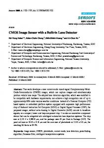
Fig. 11. Distribution plot of the output digital code error in column and row direction at 2.5 lx and 120 frames/s (a) before and (b) after applying the off-chip CFPN calibration. Fig. 13. Measured power consumption and saving rate for the column SA-ADC with respect to the frame rate before and after applying the switched power technique.
Fig. 12. Full frame image captured at 120 frames/s.
The input voltage offset of the comparator in the SA-ADC is varied with the operating frequency and temperature. In our design, the frame rate does not affect the input voltage offset of the comparator because the A/D conversion time is fixed, not varied according to the frame rate as in Fig. 3. However, the offset voltage drift in the comparator by temperature variation causes an error. When applying the off-chip CFPN calibration, the maximum CFPN is verified to 1.2 LSB from simulation results at the temperature ranged from −20 ◦ C to 80 ◦ C. When the CPFN calibration function is moved into the onchip, each column should have a memory to store the column offset map and a processing unit for the real-time CFPN correction. Recently reported column processor for SA-ADCs in [5] efficiently reduces the area and signal processing time for the CFPN calibration. The power consumption is slightly increased. However, the power consumption of the digital block in the readout circuit is relatively much lower than that of the analog block. The power consumption of the proposed column SA-ADC decreases from 115 to 41 μW when applying the switched power technique at 120 frames/s, and its power saving rate is 64%. The column SA-ADC increases the power saving rate of 85% and 58% after the switched power technique is applied at the frame frequencies of 15 and 150 frames/s, respectively, as shown in Fig. 13. The measured results show that the power consumption of the image sensor with the switched power technique is 68 and 220 mW at the frame frequencies of 15 and 150 frames/s, respectively. Fig. 14 shows the power
Fig. 14. Composition of measured power consumption before and after applying the switched power technique at a frame rate of 120 frames/s.
Fig. 15. Simulation results of the current from the supply when applying the switched power technique.
consumption breakdown when applying the switched power technique or not. The switched power technique is very useful to reduce the power consumption of the CMOS imager because analog readout circuits including the SA-ADCs and the binaryweighted reference generator occupy 65% of the overall power consumption. Whereas the proposed switched power technique does reduce the power consumption, it can cause fluctuations in the power supply and increase the random noise. The simulation results in Fig. 15 show that the peak current at the instant of power switching is similar to that at the integrating operation in the
SHIN et al.: 1.92-MEGAPIXEL CMOS IMAGE SENSOR WITH COLUMN-PARALLEL SA-ADCs
1699
TABLE I P ERFORMANCE S UMMARY
Fig. 16. Measured random noise before and after applying the switched power technique.
it uses an operational amplifier to integrate a binary-weighted reference voltage. In order to reduce the power consumption using an operational amplifier, we adopted a switched power technique. The simulated peak current and the measured random noise results show that the switched power technique can be applied to an image sensor with column ADCs using a switched capacitor circuit.
Fig. 17. Optoelectrical characteristics of the CMOS imager at 120 frames/s.
SA-ADC. Therefore, the switched power technique does not influence the image performance. The five small peak currents in Fig. 15 result from operations to recover the output commonmode voltage of AINT in Fig. 5. The measured random noise levels before and after applying the switched power technique are shown in Fig. 16. The measured results show that the switched power technique does not increase the random noise of the image sensor. Each data point in Fig. 16 was measured ten times in a dark state (less than 0.1 lx) to enhance the accuracy of the measured value. The error bar represents the min–max range. Fig. 17 shows the optoelectrical characteristics of the CMOS imager at 120 frames/s. The sensitivity of the CMOS imager is 1.6 V/lx · s, as shown in Fig. 17. A performance summary is provided in Table I. V. C ONCLUSION A CMOS image sensor with an area-efficient and low-power SA-ADC for the column-parallel readout architecture is proposed and verified by testing the image sensor. The proposed readout circuit using the SA-ADC is successfully integrated for an image sensor with a fine pixel pitch of 2.25 μm. Whereas the proposed SA-ADC reduces the area consumption compared with that of the previous SA-ADC using a capacitor array DAC,
ACKNOWLEDGMENT The authors would like to thank Prof. G. Han of Yonsei University for valuable discussions. R EFERENCES [1] S. Yoshihara, Y. Nitta, M. Kikuchi, K. Koseki, Y. Ito, Y. Inada, S. Kuramochi, H. Wakabayashi, M. Okano, H. Kuriyama, J. Inutsuka, A. Tajima, T. Nakajima, Y. Kudoh, F. Koga, Y. Kasagi, S. Watanabe, and T. Nomoto, “A 1/1.8-inch 6.4 MPixel 60 frames/s CMOS image sensor with seamless mode change,” IEEE J. Solid State Circuits, vol. 41, no. 12, pp. 2998–3005, Dec. 2006. [2] H. Takahashi, T. Noda, T. Matsuda, T. Watanabe, M. Shinohara, T. Endo, S. Takimoto, R. Mishima, S. Nishimura, K. Sakurai, H. Yuzurihara, and S. Inoue, “A 1/2.7-in 2.96 MPixel CMOS image sensor with double CDS architecture for full high-definition camcorders,” IEEE J. Solid State Circuits, vol. 42, no. 12, pp. 2960–2967, Dec. 2007. [3] T. Toyama, K. Mishina, H. Tsuchiya, T. Ichikawa, H. Iwaki, Y. Gendai, H. Murakami, K. Takamiya, H. Shiroshita, Y. Muramatsu, and T. Furusawa, “A 17.7 Mpixel 120 fps CMOS image sensor with 34.8 Gb/s readout,” in Proc. ISSCC, 2011, pp. 420–422. [4] A. I. Krymski, N. E. Bock, N. Tu, D. V. Blerkon, and E. R. Fossum, “A high-speed, 240-frame/s, 4.1-MPixel CMOS Sensor,” IEEE Trans. Electron Devices, vol. 50, no. 1, pp. 130–135, Jan. 2003. [5] S. Matsuo, T. J. Bales, M. Shoda, S. Osawa, K. Kawamura, A. Andersson, M. Haque, H. Honda, B. Almond, Y. Mo, J. Gleason, T. Chow, and I. Takayanagi, “8.9-Megapixel video image sensor with 14-b columnparallel SA-ADC,” IEEE Trans. Electron Devices, vol. 56, no. 11, pp. 2380–2389, Nov. 2009. [6] M. Furuta, Y. Nishikawa, T. Inoue, and S. Kawahito, “A high-speed, high-sensitivity digital CMOS image sensor with a global shutter and 12-bit column-parallel cyclic A/D converter,” IEEE J. Solid State Circuits, vol. 42, no. 4, pp. 766–774, Apr. 2007.
1700
IEEE TRANSACTIONS ON ELECTRON DEVICES, VOL. 59, NO. 6, JUNE 2012
[7] J.-H. Park, S. Aoyama, T. Watanabe, K. Isobe, and S. Kawahito, “A highspeed low-noise CMOS image sensor with 13-b column-parallel singleended cyclic ADCs,” IEEE Trans. Electron Devices, vol. 56, no. 11, pp. 2414–2422, Nov. 2009. [8] S. Lim, J. Cheon, Y. Chae, W. Jung, D.-H. Lee, M. Kwon, K. Yoo, S. Ham, and G. Han, “A 240-frames/s 2.1-Mpixel CMOS image sensor with column-shared cyclic ADCs,” IEEE J. Solid State Circuits, vol. 46, no. 9, pp. 2073–2083, Sep. 2011. [9] H. P. Le, J. H. Singh, and A. Stojcevski, “Ultra-low-power variableresolution successive approximation ADC for biomedical application,” Electron. Lett., vol. 41, no. 11, pp. 634–635, May 2005. [10] I. Ahmed and D. A. Johns, “A high bandwidth power scalable subsampling 10-Bit pipelined ADC with embedded sample and hold,” IEEE J. Solid State Circuits, vol. 43, no. 7, pp. 1638–1647, Jul. 2008. [11] D. A. Johns and K. Martin, Analog Integrated Circuit Design. New York: Wiley, 1997, pp. 287–291. [12] N. Verma and A. P. Chandrakasan, “An ultra low energy 12-bit rateresolution scalable SAR ADC for wireless sensor nodes,” IEEE J. Solid State Circuits, vol. 42, no. 6, pp. 1196–1205, Jun. 2007. [13] M. J. Bell, “An LCD column driver using a switch capacitor DAC,” IEEE J. of Solid State Circuits, vol. 40, no. 12, pp. 2756–2765, Dec. 2005.
Min-Seok Shin (S’05) received the B.S. degree in electronics and computer engineering from Hanyang University, Seoul, Korea, in 2005, where he is currently working toward the Ph.D. degree in electronics and computer engineering. His research interests include the analog-todigital converter and readout circuits for sensor applications.
Jong-Boo Kim (S’08) received the B.S. degree in electronic engineering from Hanyang University, Seoul, Korea, in 2007, where he is currently working toward the Ph.D. degree in electronics and computer engineering. He has been engaged in research for mixed-signal circuit design and the CMOS image sensor.
Min-Kyu Kim (S’11) was born in Ulsan, Korea, in 1983. He received the B.S. degree in electronics and computer engineering from Hanyang University, Seoul, Korea, in 2008, where he is currently working toward the Ph.D. degree in electronics and computer engineering. His research interests include readout circuits for sensor applications.
Yun-Rae Jo received the B.S. degree in electronics and computer engineering from Hanyang University, Seoul, Korea, in 2009, where he is currently working toward the Ph.D. degree in electronics and computer engineering. His research interests include the analog-to-digital converter and the CMOS image sensor.
Oh-Kyong Kwon (S’83–M’88) received the B.S. degree in electronic engineering from Hanyang University, Seoul, Korea, in 1978 and the M.S. and Ph.D. degrees in electrical engineering from Stanford University, Stanford, CA, in 1986 and 1988, respectively. From 1987 to 1992, he was with the Semiconductor Process and Design Center, Texas Instruments Inc., Dallas, Texas, where he was engaged in the development of multichip module technologies and smart power integrated circuit technologies for automotive and flat panel display applications. In 1992, he joined Hanyang University as an Assistant Professor in the Department of Electronic Engineering and is now a Professor with the Division of Electrical and Computer Engineering, Hanyang University. Since 2011, he has been serving as Provost and Senior Vice-President of Hanyang University. His research interests include interconnect and electrical noise modeling for high-speed system-level integration, wafer-scale chip-size packages, smart power integrated circuit technologies, mixed mode signal circuit design, imager, analog front-end circuit design for biomedical instruments, and the driving methods and circuits for flat panel displays. He has authored and coauthored over 253 international journal and conference papers and is the holder of 99 U.S. patents.