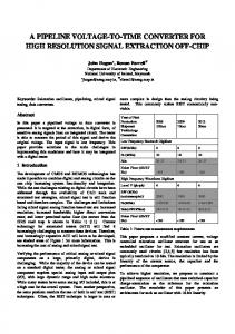
1
A 32x32 50ps Resolution 10 bit Time to Digital Converter Array in 130nm CMOS for Time Correlated Imaging. Justin Richardson[1,2], Richard Walker[1,2], Lindsay Grant[2], David Stoppa[3], Fausto Borghetti[3], Edoardo Charbon[4,5], Marek Gersbach[4,5], Robert K. Henderson[1]. [1] The University of Edinburgh, Edinburgh, UK; [2]STMicroelectronics, Imaging Division, Edinburgh, UK; [3] Fondazione Bruno Kessler, Trento, Italy; [4]EPFL, Lausanne, Switzerland; [5]TU Delft, Delft, The Netherlands;
[email protected] Tel: +44 131 336 6231 (
SUMMARY
W
e report the design and characterisation of a 32x32 time to digital (TDC) converter plus single photon avalanche diode (SPAD) pixel array implemented in a 130nm imaging process. Based on a gated ring oscillator approach, the 10 bit, 50µm pitch TDC array exhibits a minimum time resolution of 50ps, with accuracy of ±0.5 LSB DNL and 2.4 LSB INL. Process, voltage and temperature compensation (PVT) is achieved by locking the array to a stable external clock. The resulting time correlated pixel array is a viable candidate for single photon counting (TCSPC) applications such as fluorescent lifetime imaging microscopy (FLIM), nuclear or 3D imaging and permits scaling to larger array formats.
II. DESIGN As opposed to a stand-alone single TDC design, an arrayable architecture is a trade off between time resolution, word width, complexity, area, power consumption and accuracy. This is particularly evident when considering a structure that scales elegantly to large format arrays. Using ST Microelectronics’ 130nm, 4 metal CMOS Imaging process and 1.2V digital core, we employ a combined coarse-fine architecture. Coarse conversion is achieved by incrementing a ripple counter on every ring period, with fine conversion being decoded from the ‘frozen’ dynamic state of the internal nodes of the ring. The logic block generates ring oscillator differential control signals using only high-speed combinatorial logic to avoid flip-flop setup and hold violations. The block diagram of the TDC is shown in Fig.1.
I. INTRODUCTION The origins of modern time to digital conversion are rooted in nuclear science and aerospace activities of the 1960’s [1] and today may be broadly classified into two groups: those whose time resolution is based on the minimum gate delay available in the process technology, and those achieving sub-gate delay resolution. The gate delay limit may be bettered by using Vernier delay lines (VDLs) [2], pulse shrinking [3] or by interpolative means [4]. Other members of this group implement time stretching [5] and time to amplitude converter (TAC) [6] approaches. TDC’s based on the minimum gate delay are classically based on clocked delay lines as presented in the hybrid approach of [7] which also utilises a single ended ring oscillator. Converters based on the ring oscillator approach [8,9] also belong to this group and is the chosen approach for this work based on their suitability for array implementation. The recent progress of implementation of SPADs in nanometer scale CMOS now makes it possible to integrate detector and converter functions on chip to create a monolithic TCSPC system. This work constitutes the largest single-chip array of TDCs so far reported. A new TDC architecture combining small area, low power consumption and scalability at moderate resolution (50ps) is discussed.
Figure 1: TDC Block Diagram The TDC is embedded with buffer memory, glue logic and SPAD to create a 50µm x 50µm time correlated imaging pixel shown in Fig. 2.
Figure 2: Pixel Block Diagram
This work has been supported by the European Community within the Sixth Framework Programme IST FET Open Megaframe [“Million Frame Per Second, Time-Correlated Single Photon Camera”] project (contract No. 029217-2, www.megaframe.eu ).
Dynamic range can be doubled in an area efficient manner by adding one extra counter flip flop and pipeline memory element. The pixel design supports pipelined data readout and may be instantiated many times to create any desired array
2 format. The simplified timing of the pixel array operating in TCSPC reverse mode at 1Mfps is shown below in Fig. 3. pixresetn
frame n
larger resolution formats. The distribution of high-speed clocks across the chip is avoided for reasons of high quiescent power consumption, array uniformity and image code droop.
1MHz
f n+1
Vsupply start(spad) 40MHz
stop(laser) ring(fine)
VCO Control V
≈ 2GHz
}
Mp1
data acquired
increment write
1MHz
read
1MHz
a
1MHz
gnd
data
data n-1 ~275µA pk
I(Vsupply)
data n
fine data
CODER
counter increment
encode freeze
init
vdd a 3 ab
init
Mn1 Mn2
z zb ab
}
a ab
I
zb z
Figure 5: Regulated Differential Inverter Element
Alternatively, the pixel can operate in time-uncorrelated mode by simply counting the number of photon events within a defined, variable exposure time. Verification of TCSPC mode included analysis of the special cases of photon arrivals in the first and last LSB bins, and no photon arrival. Two ring oscillator designs are implemented in the same array that trade off time resolution for power consumption, referred to henceforth as slow and fast TDCs. The ring oscillator circuit and layout are a critical to the timing resolution, linearity and power consumption of the converter. The simplified schematic of this cell is shown below in Fig. 4.
a 2 ab
Mp2
leakage I
Figure 3: TCSPC Timing Diagram
a 1 ab
Mn_reg
a 4 ab
init
Calibration is achieved by locking the mean array time resolution to a stable external clock source using the PLL like structure shown below in Fig. 6.
Figure 6: PVT Calibration This structure utilises an embedded replica of the TDC ring oscillator. The locked-in VCO control voltage is broadcast across the chip to all ring oscillator supply regulation elements providing robustness to PVT variation and a means of resolution control without adding area inefficient capacitance to slow the oscillator [9]. The layout of a single pixel is shown below in Fig. 7 with the main sub-blocks identified.
init
gnd
Figure 4: Ring Oscillator Schematic A ‘power of 2’ number of differential elements is used which simplifies the fine state binary coding function without the need for look ahead logic on the last inverter [7]. Swapping polarity of feedback on the last stage ensures positive feedback oscillation. To minimise the impact of dominant supply noise induced jitter effects the cell is constructed from wide swing, differential inverters [10,11] with NMOS supply regulation as shown in Fig. 5. The regulation element also forms part of the global calibration function. A supply current of approximately 275µA peak per TDC is drawn only during the period of time that the pixel’s ring oscillator is on. The maximum duration for this is the frequency of the STOP signal. This gives a low average photon-irradiance dependent consumption profile, which is suited for low light intensity applications such as FLIM and permits scaling of the array to
SPAD & QUENCH
LOGIC
MEMORY
CODER RING OSC RIPPLE COUNTER
Figure 7: Pixel Layout
3 The pixel array is formed from two 32x16 sub arrays (slow and fast). Serialised 10-bit data is read out of two banks of 32 high-speed single ended IO buffers at 160MHz for off chip analysis. On chip supply decoupling and the formation of a low voltage drop metal power grid are essential design features. III. TEST RESULTS The converters DNL and INL are computed over the full dynamic range using the code density test method [12] as shown in Fig. 8. A diffuse light source is used as uncorrelated optical stimuli to a statistically representative TDC array element.
1.600 1.400 1.200
0.5
Slow TDC Fast TDC
0.4
1.000
0.3
Codes 0.800
0.2
0.600
0.1
0.400
0.0
0.200
1 10
0.000
-0.4
S28
Column
S31
S19
S22
-0.3
28 S25
Row
19 S13
-0.2
S16
S1 S4
-0.1
S7 S10
DNL (LSB)
Pixel to pixel jitter variation is of prime concern for architectures based on arrays of ring oscillators. Mean jitter is calculated for each TDC converting a time period of 85% of the full dynamic range, at maximum ring oscillator speed as shown in Fig. 10. A mean jitter of 0.6 LSB is calculated for the slower of the two ring oscillator designs. The faster halfarray inherently has a smaller dynamic range and so accumulates less long-term jitter, yielding a mean uniformity of 0.3 LSB.
Figure 10: TDC Jitter Uniformity 180
160
140
120
100
80
60
40
20
0
-0.5
Time (ns)
2.5
Slow TDC Fast TDC
2.0
The global calibration function was verified as shown in Fig. 11. The stable reference PLL input frequency was progressively divided and the slow TDC resolution mapped.
1.5
350 PLL out of lock
Figure 8: TDCs DNL & INL TDC uniformity across the array is calculated as 1.8% FWHM with a standard deviation of 8 codes (0.9%). Uniformity is calculated at 85% of the full dynamic range from Fig. 9 below.
PLL out of lock
150
Ideal Response
100 350
Time (ns)
200
300
-2.5
250
-2.0
250
200
-1.5
150
-1.0
300
100
180
160
140
120
100
80
60
40
-0.5
20
0.0
TDC Array Resolution (ps)
0.5 0
Reference PLL Ring Resolution (ps)
Figure 11: Global Calibration Loop Response This shows tracking between the reference PLL and TDC array over a range of input frequencies. When the array resolution cannot follow the ideal linear response of increasing input frequency the calibration system is out of lock. It can be seen that this function provides PVT resistant control equating to 3dB of TDC time resolution.
930 920 910 900 Mean Code 890 880 870 S29
860
S22
850
S15
25
29
17
Row
S8 21
13
9
5
1
INL (LSB)
1.0
S1
Figure 9: TDC Array Uniformity
Column
The array power consumption graph shown in Fig. 12 shows an offset due to the contribution of clock trees, readout, calibration block and I2C ancillary cells. The profile is linear with the number of pixels that have been excited by a photon arrival. This feature is extremely desirable for the low incident light level applications for which the device is intended and minimises the impact of thermal effects on the SPAD.
4
Core Power Consumption (mW)
50
Pslow Pfast
45 40 35 30 25 20 15 10 5 0 0
100
200
300
400
500
# Active Pixels
Figure 12: TDC Array Power Consumption Profile The device consumes an average 28µW (slow TDC) and 38µW (fast TDC) per pixel at 1.2V supply, excluding ancillary cell and IO consumptions when converting a reverse mode 10ns test stimuli period. The user may configure the device to trade off resolution, dynamic range and power consumption to suit the application. It should be noted that IO is the dominating power consumer considering that the overall 4.6 x 3.8mm device outputs a maximum 10.24Gbps. Fig. 13 shows a micrograph of the silicon chip with a zoomed in inset of a single TDC. This partly shows the wide, low resistance top metal power distribution strategy used to minimise I-R drops deep in the array.
Figure 13: 32x32 SPAD-TDC Array Micrograph TABLE I: TDC-PIXEL PERFORMANCE SUMMARY
Metric Value (slow, fast) Unit Technology 130nm, 4M-1P CMOS Word Length 10 bits Uniformity (σ) 8 (0.9%) LSB Jitter (mean) 0.6 LSB TDC Area 2200 µm2 # Transistors 580 /pix DNL/INL ±0.5/2.4 ±0.4/1.4 LSB Resolution 178 52 ps Power Consumption1 28 38 µW Chip Data Rate2 5.12 Gbps Notes: 1:per pixel converting 10ns time period, not including array 2
ancillary cells and chip IO; :on evaluation platform at 500k fps.
IV. CONCLUSIONS In this paper we have introduced the design and characterisation of a dense ring-oscillator based 32x32 TDC array with integrated SPADs to create a single chip TCSPC sensor implemented in a deep sub-micron Imaging CMOS process. The design balances area, power consumption and performance constraints to create a scalable architecture that is power efficient and is robust to process, supply and environmental effects. When coupled with an associated data processing platform (or as a future monolithic solution) this work enables low cost proliferation of a range of highresolution time resolved biological analyses and depth imaging applications. Acknowledgement: The authors are grateful to Mr. Alex Buts[1] for his contribution to device characterisation.
REFERENCES [1] NUTT, R.: ‘Digital Time Intervalometer’, The Review of Scientific Instruments, 1968, Vol. 39, Issue 9. [2] DUDEK, P., SZCZEPANSKI, S., HATFIELD, J.V.: ‘A highresolution CMOS time-to-digital converter utilizing a Vernier delay line’, Solid State Circuits, Journal, 2000, Vol. 35, Issue 2, p240-247. [3] KARADAMOGLOU, K., PASCHALIDIS, N. P., SARRIS, E., STAMATOPOULOS, N., KOTTARAS, G., PASCHALIDIS, V.: ‘An 11-bit high-resolution and adjustable-range CMOS time-todigital converter for space science instruments’, Solid-State Circuits, IEEE Journal of, 2004, Vol. 39, Issue 1, p214-222. [4] HENZLER, S. et al: ‘A Local Passive Time Interpolation Concept for Variation-Tolerant High-Resolution Time-to-Digital Conversion’, Solid-State Circuits, IEEE Journal of, 2008, Vol. 43, Issue 7, p1666-1676. [5] MINJAE, LEE, ABIDI, A. A.: ‘A 9b, 1.25ps Resolution CoarseFine Time-to-Digital Converter in 90nm CMOS that Amplifies a Time Residue’, VLSI Circuits, IEEE Symposium, 2007, p168-169. [6] SWANN, B.K. et al: ‘A 100ps Time-Resolution CMOS TimeDigital Converter for Positron Emission Tomography Imaging Applications’. IEEE Journal of Solid-State Circuits, vol. 39, p1839– 1852, 2004. [7] ARAI, Y., IKENO, M.: ‘A time digitizer CMOS gate-array with a 250 ps time resolution’, Solid-State Circuits, IEEE Journal of, 1996, Vol. 31, Issue 2, p212-220 [8] HELAL, B. M., STRAAYER, M. Z., GU-YEON, WEI, PERROTT, M. H.: ‘A Low Jitter 1.6 GHz Multiplying DLL Utilizing a Scrambling Time-to-Digital Converter and Digital Correlation’, VLSI Circuits, 2007 IEEE Symposium on, p166-167. [9] DE HEYN, V., VAN DER PLAS, G., RYCKAERT, J., CRANINCKX, J.: ‘A fast start-up 3GHz-10GHz digitally controlled oscillator for UWB impulse radio in 90nm CMOS’, Solid State Circuits Conference. ESSCIRC 2007. 33rd European, p484-487. [10] HERZEL, F., RAZAVI, B.: ‘A Study of Oscillator Jitter Due to Supply and Substrate Noise’, Circuits and Systems II: Analog and Digital Signal Processing, IEEE Transactions on, 1999, Vol. 46, Issue 1, p56-62. [11] NISSINEN, I., MANTYNIEMI, A., KOSTAMOVAARA, J.: ‘A CMOS time-to-digital converter based on a ring oscillator for a laser radar’, Solid-State Circuits Conference, ESSCIRC '03, Proceedings of the 29th European, p469-472. [12] DOERNBERG, J., LEE, H. S., HODGES, D. A.: ‘Full-speed testing of A/D converters’, IEEE J. of Solid-State Circuits, Vol. 19, no. 6, Dec. 1984, p820-827.