composed of eleven low noise input channels and a dedicated digital audio processor. Analog input signals are provided through an eleven microphone array.
A 3v 0.5 µm CMOS A/D Audio Processor for a Microphone Array F. Balestro*, V. Fraisse*, G. Martel*, D. Morche*, P. Senn* G. Le Tourneur ** ,Y. Mahieux** * France Telecom - CNET Grenoble - BP 98 - 38243 Meylan cedex - FRANCE ** France Telecom - CNET Lannion - BP 40 - 22301 Lannion cedex FRANCE
Abstract A 0.5 µm 3V CMOS mixed-mode audio processor is presented. It is mainly composed of eleven low noise input channels and a dedicated digital audio processor. Analog input signals are provided through an eleven microphone array. The chip size is about 50 mm2 and the power dissipation is less than 100 mW. This circuit is dedicated to multimediaapplications.
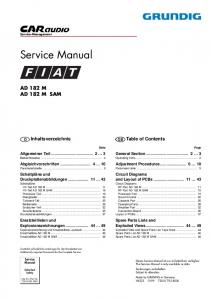
System environment In teleconference systems and handfree telephone sets as well as in multimedia workstations with audio interfaces, picked up speech signals are disturbed by the acoustic environment (room effect and ambient noise). The microphone array has been demonstrated as an efficient technique to improve the speech quality in various applications {1}. In a microphone array, the signals picked up by the several sensors are combined such that the useful signals are coherently summed and therefore enhanced with respect to the disturbing signals. Previous studies {2} have shown the improvement in the speech quality obtained from a specific array composed of eleven low cost unidirectional microphones, compared to a single microphone (see directivity patterns of the array in Figure 1). Figure 2 presents the basic scheme of the array. In order to achieve a control of the directivity pattern over the frequency range [100 Hz, 7 kHz ], the sensors are grouped into 4 sub-arrays. Each sub-array is characterized by a specific inter-sensor spacing ans is dedicated to a part of the frequency range by means of a band of filters. The characteristics of the sub-arrays are the following: * 1-low frequencies (100Hz - 1 kHz), spacing : d1=20 cm, 2 microphones plus 2 "side" microphone * 2-medium frequencies 1 (1 kHz - 2 kHz), spacing : d2=10 cm, 5microphones * 3-medium frequencies 2 (2 kHz - 4 kHz), spacing : d3=5 cm, 5microphones * 4-high frequencies (4 kHz - 7 kHz), spacing : d4=2.5 cm, 5microphones. Coherent summation of the speech signals is obtained by arranging the microphones on the arc of a circle with the center located at the speaker's mouth. In order to reduce the cost of the whole system, as well as the volume of the equipment, a dedicated chip has been designed. A 0.5 µm CMOS process, including high quality (double poly) capacitors has been used and specific layout rules applied in order to maintain a high S/N ratio, in spite of the 3 volt power supply and the 7 kHz bandwidth signal. Circuit Description Figure 3 presents the architecture of the circuit. The eleven microphone preamplifiers have not yet been implemented within the chip for noise considerations. The eleven analog full differential input signals are again amplified
Microphones Preamplifiers (40 dB gain)
Adders
Filtering
RIF1 f 1000 10 cm
5 cm
RIF2
2.5 cm
f 2000
2.5 cm
RIF3 4000
f
RIF4 f 7000
Figure 1: Measured directivity patterns of the array for the octave bands centered around 500 Hz ( __), 1 kHz (--), 2 kHz ( ....) and 4 kHz (-.-.-). Analog Output
2,048 Mhz ²3
²3
mixing
256 Khz
4,096Mhz analog filter
² 2
64 Khz
64 Khz
Sinc3
16 Khz
Sinc4
7Khz
M=32
M=4
Sinc4
7Khz
M=32
Figure 2 : Practical realization of the microphone array
M=4
16 Khz 7Khz
16 Khz RIF1 f 1000
RIF2 f 2000 16 Khz 125Hz
²3
Sinc4
7Khz
M=32
²3
Sinc4
M=4
7Khz
M=32
M=4
RIF3 f 4000
Digital Output
RIF4 f 7000
Figure 3 : Chip Architecture
These low noise amplifiers {3} allow the global and individual gain of each channel to be adjusted if necessary from -20 dB to + 20 dB, with a 0.5 dB step. The eleven signal are then mixed in order to obtain the four (low, medium 1, medium 2 and high frequency) signals. These four signals are then digitalized thanks to four third order 2 MHz delta-sigma converters. The four 2 MHz digital signals are down sampled to 64 kHz after Sinc4 blocks. After this first down sampling, the spectrum of these four signals is limited to 7 kHz with four identical 9th order IIR filters, implemented with a bit-serial architecture. The four signals are then directly down sampled to 16 kHz and sent to four different FIR filters, in order to retain the desired part of the input signal spectrum coming from each sub-array and to eliminate the other unwanted components. The four transfer functions of the RIF are presented in Figure 4 and 5 and they are made of 61 st. order symmetrical filters. The four signals are then directly recombined (adder) and a last IIR high-pass (cut-off frequenciy of 125 Hz) filter eliminates all the
undesirable DC and low frequency parts of the signal. A simple dual single D/A channel has also been implemented in order to provide a local analog control signal. dB 0 -10 -20 -30 -40 -50 -60 -70
Hz
Hz
-80 0
1000
2000
3000
4000
5000 6000
7000 8000 0
1000
2000
3000
4000
5000 6000
7000
8000
Figures 4 - 5 : FIR transfer functions (two sets of coefficient)
Circuit Optimization All the digital parts have been implemented by using a top-down synthesis approach. The digital optimization has been made at the architectural level, by using specific bit-serial VHDL generators for the IIR filters and a generator of filters bank for the FIR part. Two sets of coefficients have been implemented for the FIR filters, and the complexity of the digital part is about 250 K transistors. Specific care has been taken with the layout of the analog part. The main constraints arise from the 3 v power supply and the bandwidth of the signal (7 kHz). The input variable gain amplifiers can adjust the level of each channel, in a range from -20 dB to + 20 dB (for a global gain adaptation and for specific microphone corrections, if necessary). The amplifier has been optimized for high linearity (100 dB THD), low noise (1.1 µV in a 7 kHz bandwidth) and low power (less than 4 mW/Aop with 3v power supply). The gain adjustment of the eleven input amplifiers is made through the variations of eleven independant differential resistor ladders. In order to maintain a high SNR, about 120 dB in a 7 kHz bandwidth, large input stage transistors have been used for these amplifiers (e.g. 250µm/100µm for the NMOS load), making each of them as space consuming as 10 k digital transistors. This is certainly an economic limitation for further low-noise mixed-mode development with lower supply voltage and high quality analog processing. The four A/D converters are built around classical 2+1 ord. MASH structures. The analog coefficients have been optimized in order to reduce the dynamic range at the integrator outputs and the SNR, measured on stand-alone converters, using the same architecture and the same process, is better than 98 dB in a 7 kHz bandwidth. Due to the existence of the five input analog (capacitor) adders in front of each DS, the input thermal noise is added and so reduce the input dynamic range. One solution is to increase the input capacitance, with the constraint of a large first amplifier capacitive load. An optimization has been made in order to guarantee a SNR of better than 80 dB in the 7 kHz bandwidth, in spite of all the couplings between the digital and analog parts. The layout of the delta-sigma converters has been obtained automatically, taking into account analog routing constraints. Results Measurements have shown a very good agreement with the simulations. The digital part is fully fonctionnal and the ananalog measurements have shown very low degradations due to digital crosstalks. Figure 6 shows the A/D delta-sigma output spectrum of a 1 kHz input signal with a maximum
input level (for THD analysis) and the delta-sigma output spectrum corresponding to an 9 kHz input level of - 60 dB for SNR measurement (with the digital part off). Table 1 summarizes the main electrical features of the chip and Figure7 shows the microphotograph of the whole chip. Acknowledgements : We would like to thank Brigitte Lucas and Luc Sponga for the layout and Jean-Paul Laval for the measurements.‘ References (1) J.L. Flanagan, D.A. Berkley, G.W. Elko, J.E. West, M.M. Sondhi :"Autodirective Microphone Systems", Acustica, Vol. 73, 1991, pp 58-71 (2) Y. Mahieux, G. Le Tourneur, A. Gilloire, A. Saliou, J.P. Jullien: "A Microphone Array for Multimedia Workstations", Third Intern. Workshop on Acoustic Echo Contreol, Sept. 1993, Plestin les Grèves, France (3) E. Compagne, G. Martel, P. Senn :"A -100 dB THD, 120 dB SNR programmable Gain Amplifier in a 3.3 v 0.5 µm CMOS Process", ESSCIRC'95, September 1995, Lille, France
Figure 6: Delta-Sigma output (max. input level @ 1 kHz) Delta-Sigma output (-60 dB input level @ 9 kHz)
Figure 7 :Circuit Microphotograph
Table 1 Chip Size 33 mm2 (with pads) Digital part 10 mm2 and 250 K tr Analog part (Area) 12 mm2 Power supply 3.3 v (3V min) Power consumption < 100 mW SNR A/D (7 kHz bandwidth) > 90 dB THD > 90 dB Process 0.5 µm double poly CMOS
∆Σ ∆Σ ∆Σ ∆Σ
Voltage Reference and D/.A Analog part
AOp AOp AOp
AOp AOp AOp AOp AOp AOp AOp AOp
Digital Part (250 k Tr.)