A 61.5dB SNDR Pipelined ADC Using Simple Highly-Scalable Ring Amplifiers Benjamin Hershberg, Skyler Weaver, Kazuki Sobue†, Seiji Takeuchi†, Koichi Hamashita†, Un-Ku Moon †
Oregon State University, Corvallis, OR, USA; Asahi Kasei Microdevices, Atsugi, Japan
[email protected],
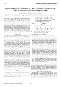
[email protected] Abstract A ring amplifier based pipelined ADC is presented that uses simple cells constructed from small inverters and capacitors to perform amplification. The basic ring amplifier structure is characterized and demonstrated to be highly scalable, power efficient, and compression-immune (inherent rail-to-rail output swing). The prototype 10.5-bit ADC, fabricated in 0.18µm CMOS technology, achieves 61.5dB SNDR at a 30MHz sampling rate and consumes 2.6mW, resulting in a FoM of 90fJ/conversion-step. Introduction Performing accurate, power efficient amplification in scaled CMOS technologies remains a persistent and pressing challenge. Reduced supply voltages and intrinsic device gains exacerbate the accuracy/power trade-off imposed by the deleterious effects of finite amplifier gain error. Many effective solutions to this problem have been developed - ranging from analog gain-enhancement techniques, digital correction schemes, and even altogether new amplification paradigms – but the solutions often come with a penalty in the classic speed/power/accuracy tradeoff relationship. Furthermore, the operational paradigm for most amplifier implementations remains based on RC-type settling, which when driving large capacitive loads, benefits little from process scaling (i.e. power-delay product improvements). In other words, most existing approaches to scalable amplification work by masking the symptoms of the disease rather than actually curing it. To cure such a problem, an entirely new amplification paradigm is required – one which is inherently suited to operate in modern and future scaled environments. Ring Amplification This paper explores the concept and practical application of ring amplification. The basic structure of a ring amplifier (alternately: ring amp, RAMP) is shown in Fig. 1, and is the actual transistor-level implementation used in the ADC presented in this paper. The ring amp is effectively a ring oscillator whose input signal takes two separate paths to the output (in fact, for VRP = VRN, it is functionally equivalent to a 3-inverter ring oscillator). When VRP > VRN, the capacitors C2 and C3 will embed different voltage offsets in each signal path such that for a certain range of input values, neither MP3 nor MN3 will conduct. As seen in Fig. 2, this non-conduction region, or dead-zone, creates plateaus in the output (and input) waveforms of the amplifier as it oscillates. These plateaus reduce the average gain of the amplifier, and for a sufficiently large dead-zone, the average gain will be reduced enough that the unity-gain frequency now corresponds to a phase shift of less than 180°. When this criterion is met, the oscillator will begin to stabilize and settle. This will occur very quickly (much quicker than the “teaching” example of Fig. 2) due to two key feedback mechanisms which continue to dynamically reduce the effective gain of the ring amplifier (and thus increase phase margin and stability). The first mechanism is due to the fact 978-1-4673-0849-6/12/$31.00 ©2012 IEEE
VRN 2.52µm 240nm
C1
320nm 160nm
840nm 160nm
MP3
VBP 320nm
C2
Φrst
VIN
Φrst
960nm 320nm
160nm
100fF
VOUT
VA
320nm 160nm
C3
100fF
840nm 160nm
100fF 960nm 240nm
Φrst
320nm 160nm
VBN
320nm 160nm
MN3 320nm 320nm
VRP
Fig. 1: Complete transistor-level ring amplifier structure with the actual component values used in the fabricated design.
Fig. 2: Example ring amplifier operation for an exaggerated case (large dead-zone, excessive drive current, low bandwidth) biased at the edge of stability (used to illustrate concepts).
that the input error amplitude will decrease (via settling), but the input-referred amplitude of the dead-zone will not. Thus, the percentage of time spent in the dead-zone increases, decreasing the effective gain. The second source of feedback comes from the progressive decrease in the value of both the maximum and average overdrive voltage (VOV) applied to MP3/MN3. A linear reduction of VOV corresponds to a quadratic reduction in slew-rate, and since the slew-rate and gain of a ring amp are linearly related, this rapidly lowers the effective gain. Power Efficiency and Scalability Features Ring amplifiers operate in a fundamentally different way than conventional opamps, and this gives them a unique set of characteristics, many of which are ideally suited for use in modern low-voltage CMOS technologies. Whereas a conventional class-A or class-AB opamp charges its output load with some form of RC-based settling, the output transistors MP3/MN3 in the ring amplifier behave like digitally switched current sources, and charge the output with 2012 Symposium on VLSI Circuits Digest of Technical Papers
32
ФS ФS
VIN+ D·VREF
ФA
200fF
ФA RAMP
200fF
ФA ФS
VOUT+
ФSE
ФSE
-D·VREF VIN-
ФA
VCMX
ФSE 200fF 200fF
RAMP
ФA
ФS
VOUT-
ФA
Fig. 3: Pseudo-differential float-sampled 1.5b MDAC structure.
slew-based settling. When initially switched on, MP3/MN3 are biased with the maximum VOV possible, and even small transistor sizes can source large amounts of dynamic current to the output. In addition to conserving power, this effectively decouples the ring amp’s internal power requirements from that of the output load size, and allows the ring amp to charge large capacitive loads with extreme efficiency. This highly-digital, switched behavior and weak dependence on output load size also enables the structure’s power-delay product to scale particularly well with respect to modern CMOS process technologies. The propagation delay through the ring amp inverter chain directly affects its power-speed-accuracy product (i.e. FoM), and scales according to digital process performance since the power-delay product of an inverter decreases approximately linearly in accordance with decreasing feature size [1]. In other words: smaller process technologies lead to faster, more efficient ring amps. The effect of supply voltage scaling is another core concern in modern processes, and maximizing amplifier output swing is imperative in order to maintain high SNR. Ring amplification turns out to be inherently compatible with this scaling challenge, since the accuracy of a ring amp is determined almost exclusively by the amplitude of its input-referred dead-zone, which only depends on the gain of the first stage inverter. This makes ring amplifiers completely immune to output-swing compression, and they can operate under full rail-to-rail output swing with no increase in distortion. The only practical limitation for choosing an output swing size is settling speed: if the output transistors are forced deeply into the linear region, the output will settle with a slower RC-type behavior. ADC Implementation The 10.5-bit pipelined ADC consists of 9 nearly identical 1.5b pseudo-differential MDAC stages, and a 1.5b backend flash. The MDAC structure used is shown in Fig. 3. Unlike [2], which uses ring amps to assist conventional opamp settling, this design only uses ring amplification, and is fully compatible with process scaling. Due to the lack of common-mode feedback (CMFB), the MDAC employs the float sampling scheme of [3]. If a fully differential MDAC is desired, the CMFB scheme of [2] can be used. Measured Results The pipelined ADC was fabricated in a 1P4M 0.18µm CMOS technology. At 30MHz sampling rate, the ADC achieves 61.5dB SNDR, 61.9dB SNR, and 74.2dB SFDR. Total power consumption is 2.6mW, with 90µW consumed per ring amplifier. The measured ERBW is greater than 15MHz, and the Figure-of-Merit (FoM) is 90fJ/conversion-step. To demonstrate the key scalability benefit of output-swing 978-1-4673-0849-6/12/$31.00 ©2012 IEEE
Fig. 4: Performance summary and measured output spectrum.
Fig. 5: Characterization of rail-to-rail operation showing output compression-immunity (left) and dead-zone vs. SNDR sweep (right).
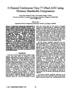
Fig. 6: Die Micrograph
compression immunity, the analog supply was reduced to 1.2V, the MDAC references were set to the supply voltages (0V and 1.2V), and the sampling frequency was reduced to 4MHz, with all other settings left unchanged. As seen in the left plot of Fig. 5, the ring amp maintains linearity even in true rail-to-rail operation, and only begins to degrade within +/-15mV of the negative/positive supplies due to insufficient RC settling time. The right plot of Fig. 5 shows the effect of dead-zone variation on SNDR. As can be seen, there is a wide, stable range of dead-zone values for which performance is largely unchanged. The ADC presented in this paper is designed to serve as a characterization test-bench, and its intentional simplicity leaves much room for improvement. Analog power can be reduced by nearly half of that reported in this work by simply disabling the ring amps when not in use (during the sampling phase), as is detailed in [2]. Additionally, optimization techniques such as stage-scaling and multi-bit MDACs, as well as simply moving to a smaller process, can be used to further improve FoM. References [1] [2] [3]
H. Iwai, “CMOS Scaling Towards Its Limits,” Solid-State and Int. Circuit Technology, 5th Intl. Conf. on, pp. 31-34, Oct. 1998 B. Hershberg, et. al. “Ring Amplifiers for Switched-Capacitor Circuits,” in IEEE ISSCC 2012 Dig. Tech. Papers, Feb. 2012 J. Li and U. Moon, “A 1.8-V 67-mW 10-bit 100-MS/s Pipelined ADC using Time-Shifted CDS Technique,” IEEE J. Solid-State Circuits, vol. 39, no. 9, pp. 1468-1476, Sept. 2004.
2012 Symposium on VLSI Circuits Digest of Technical Papers
33