4-Channel Continuous-Time 77 GSa/s ADC using Photonic Bandwidth Compression Jason Chou, George A. Sefler, Josh Conway, George C. Valley Electronics and Photonics Laboratory, The Aerospace Corporation, El Segundo, CA 90009-2957
[email protected]
Bahram Jalali Department of Electrical Engineering, University of California, Los Angeles, CA 90095 within each channel (after the filter bank), its bandwidth requirement is substantially reduced. Nevertheless, a primary drawback is the effect of post processing. Here, digital local oscillators and digital signal processing (DSP) move multiple bands into the correct frequency locations and transform them into a time-domain waveform. The extensive DSP necessary in bandwidth interleaving can introduce unwanted artifacts and distortion, especially if signals span multiple frequency bands. Both architectures require a substantial processing payload at the front-end RF amplifier or back-end DSP— neither of which are attractive in extending to higher sample rates and bandwidths while maintaining signal fidelity.
Abstract— A four-channel continuous-time implementation of photonic bandwidth compression technique is reported. In our approach, which is based on the transient time-stretched analogto-digital converter (ADC) technology, continuous high speed RF signals are segmented in the time domain and multiplexed into an array of parallel channels. The segments in each channel are temporally stretched, or equivalently compressed in bandwidth, before digitization. Benefits of our technique include multiplying the effective sample rate and input bandwidth of an ADC. Segments from all 4-channels are concatenated to form the continuous signal using an out-of-band real-time calibration tone to independently correct for gain and timing errors. In this paper, a 4-channel continuous-time architecture is demonstrated that increases the bandwidth and sampling rate of a state-of-the-art real-time 50 GSa/s digitizer by 55%. A 4-channel system is of particular interest because it matches the number of input channels available on commercial oscilloscopes. The results indicate a viable path to a 4-channel continuous-time system that would be capable of enhancing existing digitizers by more than 300% and achieving 150 GSa/s over 50 GHz in real-time.
Recently, photonic bandwidth compression has been shown to significantly enhance the performance of ADCs for time-limited signals [3,4]. Single-shot real-time sampling rates up to 10 Tera Sa/s have been demonstrated [5]. In this approach, the time interval of the input RF signal must be less than the duration of a chirped optical pulse, typically a few nanoseconds. However, many applications, such as ultra wideband communication, need to process high-speed RF signals continuously in time. This mode of operation can be achieved by a different architecture employing a repetitively swept carrier stretched to continuous-time and a parallel array of M digitizing channels [6-8]. In this paper, a 4-channel realization of a continuous-time photonic bandwidth compressor is demonstrated for the first time. The system also incorporates a state-of-the-art time-interleaved 50 GSa/s/channel real-time oscilloscope which is enhanced to 77 GSa/s, a 55% improvement. Finally, we demonstrate a realtime calibration scheme using an out-of-band tone to independently correct for gain and timing errors between adjacent segments which, when joined, form the digitized original input signal. Continuous bandwidth compression, using our photonic technique, can provide a front-end tool to boost the performance of any digitizer by reducing the requirements of the RF amplifier and avoiding DSP intensive algorithms.
I. INTRODUCTION In the area of real-time high performance digitizer design, resources from many ADCs are combined to achieve aggregate sampling rates far beyond the capabilities of a single converter. Two of the most common approaches are time and bandwidth interleaving. In time-interleaved systems, a wideband signal may be captured by an array of sub-Nyquist ADCs with slightly skewed sample clocks [1]. Next, sampleto-sample interleaving is performed in the time domain via precise calibration of the timing and gain/offset through multiple paths. However, a major bottleneck exists at the front-end RF amplifier found in each channel which must be designed to accommodate the end bandwidth of the instrument. This will limit the extent to which timeinterleaving can capture ultra-fast waveforms. In a different architecture, bandwidth-interleaved systems use a bank of filters to separate a wideband signal into channels which are downconverted to within the bandwidth capability of the acquisition channel [2]. Since the RF amplifier is placed
1-4244-1168-8/07/$25.00 ©2007 IEEE.
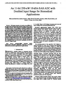
The concept of photonic bandwidth compression can be described by the basic architecture used for time-limited signals, as depicted in Figure 1(a). A broadband optical pulse
54
RF Input
D1
D2
T
(a)
of chirped optical pulses. Next, each pulse is divided into 4 segments, each of duration S, and demultiplexed into an equal number of channels. Fortuitously, this multiplexing can be performed without a fast switching gate by using a passive wavelength-division-multiplexer (WDM) [8]. Within each channel, the duty cycle is reduced to 25% and the maximum allowable stretch factor is T/S = 4. A dispersive element is used to magnify the temporal profile of the pulse by M which is then digitized by an ADC. Finally, the digitized continuous time signal is concatenated in the time domain by interleaving sequential segments together.
MZM Broadband Pulse
Chirped Optical Pulse
Continuous RF Modulation:
Modulated Pulse
Stretched Pulse
Time Stretch ×M
ADC
CH2
×M
ADC
CH3
×M
ADC
×M
ADC
T = 1/frep S CH4
CH1
CH2
CH3
CH4
(b)
CH1
W D M
Time / Wavelength CH4
Continuous Digital Output:
S
Segment Interleave
CH1
II.
INDEPENDENT REAL-TIME CALIBRATION
For an M channel system, the maximum stretch ratio is M. In practice, however, the stretch factor is less than the number of channels to account for a finite overhead needed to interleave the segments. The most bandwidth efficient approach to accomplish this is to employ a WDM with interchannel crosstalk. Traditionally, leakage between adjacent channels is not desirable in WDM communication links. However, this property can be used to create redundancy between adjacent channels for segment interleaving. A WDM designed with intentional crosstalk is discussed in the next section. Figure 2 illustrates the digitized output of two adjacent channels with a finite overlap region. The common time samples between segments are used to estimate clock skew, offset, and gain mismatch found in continuous bandwidth compression arrays [6]. An adaptive online calibration scheme has been shown to estimate error using the actual signal [7]. However, this approach could place restrictions on the input waveform, such as a minimum analog bandwidth, to achieve a desired level of accuracy.
M×S
Stretched Time
Figure 1. Conceptual diagram of an (a) time-limited and (b) continuoustime 4-channel bandwidth compressor. MZM: Mach-Zehnder modulator. WDM: wavelength division multiplexer. ADC: analog-to-digital converter.
source is generated and chirped using a chromatic dispersion device, such as optical fiber, with dispersion parameter D1. Next, a high-speed RF signal is modulated onto the envelope of the chirped optical pulse. It is intuitively clear that the time interval of the input signal must be shorter than the duration of the chirped optical pulse, T, entering the modulator. Additional chirp is applied through a second dispersive device which results in a time-stretch magnification factor, M = (D1 + D2) / D1, [4]. Equivalently, the input signal bandwidth, fRF, is compressed to fRF/M. We note that the term bandwidth compression used in this paper should not be confused with the more common process of frequency downconversion to an intermediate frequency (IF) stage. In compression, the bandwidth and center frequency of the signal are simultaneously reduced, whereas the bandwidth does not compress during downconversion. Finally, an optical-toelectrical converter recovers the RF signal for digitization. The optical pre-processing of the RF signal results in an M× multiplication of the effective sample rate and input bandwidth.
A more robust design to perform real-time calibration is to include a dedicated out-of-band RF tone along with the input signal. This allows for errors in segment interleaving to be corrected independently from variations in the signal. The deterministic nature of a tone also provides a high fidelity waveform that is preferred for calibration purposes. In practice, the real-time processing may be performed for each individual overlap region. First, the out-of-signal-band RF tone is digitally filtered by a narrow bandpass. Next, overlap of the calibration tone determines the gain and timing offset that will maximally combine the calibration tone, and thus the input signal, within the two segments. Note that inclusion of a calibration tone does slightly reduce the permissible signal bandwidth. In addition, careful measures should also be taken to minimize intermodulation products between the signal and
Optical dispersion, used to stretch the waveform, also introduces an RF frequency fading known as dispersion penalty. This occurs due to destructive interference between the frequency mixing terms of the upper and lower modulation sidebands of the optical carrier. Single-sideband modulation has been proposed and demonstrated as a possible solution to extend the analog bandwidth [9]. An alternative technique using phase diversity has also been proposed and demonstrated to eliminate this bandwidth limitation [8, 10]. Figure 1(b) describes an ideal 4-channel architecture to perform bandwidth compression for continuous-time signals. In this scheme, a repetitively swept continuous-time carrier may be obtained by chirping the adjacent optical pulses such that T = 1/frep, where frep is the repetition rate of the pulse source. RF signals are modulated onto the continuous stream
Figure 2. Illustration of two adjacent channels with a finite overlap region.
55
1
calibration tone. This can be mitigated by judicious frequency selection, low modulation index, and monitoring the modulator bias.
Normalized Attenuation
III.
CH4
4-CHANNEL BANDWIDTH COMPRESSION E XPERIMENT
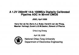
The experimental setup of a four channel continuous-time bandwidth compressor is illustrated in Figure 3. All optical components used are fiber-based in the 1550 nm band and from commercial suppliers. A 20 MHz broadband pulse source is filtered to 9 nm before it is chirped by dispersion compensating fiber (DCF) of parameter D1 = -1635 ps/nm. DCF is chosen by its high dispersion-to-loss ratio relative to normal single-mode fiber. Then, an Erbium doped fiber amplifier (EDFA) is used prior to a 4× repetition rate multiplier. This is required to adjust the interpulse period of the source to achieve continuous-time operation with D1. A Mach-Zehnder (MZ) amplitude modulator simultaneously converts an 11 GHz input signal and 3 GHz calibration tone into the optical domain. Next, a second EDFA is used followed by a DCF fiber having a dispersion of -656 ps/nm. A chirped fiber Bragg grating (CFBG) based WDM is used to separate the signal into four parallel channels. Its dispersive nature provides an additional dispersion of -250 ps/nm. The total dispersion found after the modulator is therefore D2 = 906 ps/nm. Hence, the resulting bandwidth compression factor is M = 1.55. Finally, four amplified photodetectors are used to convert the signal from the optical to RF domain. Each channel is digitized in real-time at 50 GSa/s and over 16 GHz in analog bandwidth by a TektronixTM DSA72004 oscilloscope. The scope represents the present state-of-the-art in multi-channel high performance digitizers. As a result of continuous bandwidth compression, the effective sampling rate and input bandwidth have been enhanced by 55% to 77 GSa/s and 25 GHz.
frep=20 MHz
frep x4
9nm
MZM
0.4
1546
1548
1550
1552
1554
1556
Figure 4. Optical spectrum of CFBG WDM used in the four-channel continuous-time stretch experiment.
the 3-dB crossover at the midpoint of an overlap region, and (2) after the waveforms are digitized, the corners help to identify the start and stop points of each passband. In order to study the effects of real-time calibration, the degree of overhead, and thus, the bandwidth compression factor M, is conservatively chosen for this particular experiment. We project this overhead can be readily reduced and continuoustime enhancement factors can reach above 300% in a 4channel system. Figure 5 shows the digitized output of the 11 GHz signal which has been slowed to 11/1.55 = 7 GHz across all four channels. The dashed boxes indicate regions where sequential segments carry redundant information, which correspond to the overlap in the spectrum shown in Figure 4. The letter notation “A” through “J” specifies the order in which the segments are concatenated. Offline calibration is needed to determine the static delay between optical and electrical path lengths of each channel. This can accurately be performed using a 1-ps pulse laser. The overlap section for two adjacent channels is shown in Figure 6 (a) and (b) where the gain and timing mismatch are clearly visible. These errors, if left uncorrected, generate spurious tones and deteriorate the system dynamic range [6]. A real-time calibration tone at 3 GHz is used to estimate the gain and timing mismatch, and subsequently, correct for errors found in the 11 GHz input signal. The estimated gain mismatch for this overlap region is 1.12 and the timing mismatch (relative to the sample interval) is 0.55. Figure 6 (c) and (d) shows the overlapped sections after correction. Because an independent and deterministic calibration tone is used, the effects of inter-channel as well as intra-channel errors can be corrected. Inter-channel mismatch corresponds to the sample clock skew between two channels from a difference in relative path lengths. Intra-channel mismatch is due to the errors within a single channel that arise from the optical pulse source such as amplitude stability and timing jitter. The ultimate performance of the calibration technique is limited by the noise in the system.
RF Combiner Calibration Tone
W D M
0.6
Wavelength (nm)
-656 ps/nm
50 GSa/s/CH 16 GHz Real-Time Digitizer
0.8
1544
Input Signal
EDFA
CH1
0
-1635 ps/nm BP Filter
CH2
0.2
The transmission spectrum of the CFBG-based WDM without any external modulation is shown in Figure 4. The filter profiles are custom designed to exhibit a trapezoidal shape with approximately 50% overhead, defined by the fraction of overlap bandwidth to the overall bandwidth. The trapezoidal design is helpful in the calibration for two reasons: (1) a linear transition before and after each pass band keeps
Broadband Pulse Source
CH3
EDFA -250 ps/nm
Figure 3. Experimental setup of a 4-channel continuous-time bandwidth compressor. BP: bandpass. EDFA: Erbium doped fiber amplifer. MZM: Mach-Zehnder modulator. WDM: wavelength division multiplexer.
56
3GHz (cal. tone)
(a)
(a) D
CH 1
11GHz (signal) (b)
H
BEORE: A
CH 2
E
I
B
CH 3
F
J
C
CH 4 0
5
(c) AFTER:
G
10
15
20
(d)
25
30
(b)
Stretched Time (ps) 0
1
2
3
4
Stretched Time (ps)
Figure 6. Overlap region between two adjacent channels. Visible gain and timing mismatch is exibited in the stretched 3 GHz calibration tone (a) and 11 GHz signal (b). Offset errors in the 3 GHz sine curve are estimated and used to maximally combine the calibration tone (c) and signal (d). The symbols are sample points and the lines are the fitted sine curves.
5
Input Time (ns) Figure 5. Measured 11 GHz signal digitized across all four channels. The symbols are sample points and the lines are fitted sine curves. (a) Channels 1 through 4. (b) Zoomed in portion of a segment in Channel 1.
REFERENCES
IV. CONCLUSION In summary, we have demonstrated the first 4-channel continuous-time implementation of the bandwidth compression technique. Not possible using electronic techniques such as time and frequency interleaving, this approach uses photonics to stretch an RF signal in time. We experimentally demonstrate a 4-channel system that enhances a state-of-the-art 50 GSa/s digitizer by 55%. In addition, a real-time calibration tone is employed to correct for intrachannel and inter-channel gain and timing mismatches. By optimizing the overlap of the time segments, we estimate a 4channel system could enhance presently available digitizers to achieve real-time sampling of more than 150 GSa/s over 50 GHz.
J. Pickerd, “DSP in high performance oscilloscopes,” TektronixTM White Paper, March 2005. [2] P. Pupalaikis, “Digital bandwidth interleaving,” LeCroyTM Technical Brief, March 2005. [3] B. Jalali and F. Coppinger, “Data conversion using time manipulation.” United States Patent Number 6288659, 2001. [4] Y. Han and B. Jalali, “Photonic time-stretched analog-to-digital converter: Fundamental concepts and practical considerations,” Journal of Lightwave Technology, Vol. 21, No. 12, pp. 3085-3103, December 2003. [5] J. Chou, O. Boyraz, and B. Jalali, “Femto-second real-time single-shot digitizer,” APS Annual Meeting, ABSTRACT #R9.00007, Baltimore, MD, March 2006. [6] B. Asuri, Y. Han, and B. Jalali, ”Time-stretched ADC arrays,” IEEE Transactions on Circuits and Systems—II: Analog and Digital Signal Processing, Vol. 49, No. 7, pp. 521-524, July 2002. [7] Y. Han, B. Rezaei, V. Roychowdhury, and B. Jalali, “Adaptive online calibration in time stretched ADC arrays,” Instrumentation and Measurement Technology Conference, Vail, CO, pp. 1212-1216, May 2003. [8] Y. Han and B. Jalali, “Continuous-time time-stretched analog-todigital converter array implemented using virtual time gating,” IEEE Transactions on Circuits and Systems—I: Regular Papers, Vol. 52, No. 8, pp. 1502-1507, August 2005. [9] J. M. Fuster, D. Novak, A. Nirmalathas, and J. Marti, “Single-sideband modulation in photonic time-stretch analogue-to-digital conversion,” Electron. Lett., Vol. 37, No. 1, pp. 67-68, January, 2001. [10] Y. Han, O. Boyraz, and B. Jalali, “Ultrawide-band photonic timestretch A/D converter employing photonic phase diversity,” Transactions on Microwave Theory and Techniques, Vol. 53, No. 4, pp. 1404-1408, April 2005. [1]
ACKNOWLEDGMENT This work was supported under The Aerospace Corporation's Independent Research and Development Program.
57