Nanowatt Range Folding-Interpolating ADC Using Subthreshold Source-Coupled Circuits Armin Tajalli* and Yusuf Leblebici Ecole Polytechnique Fédérale de Lausanne (EPFL), {armin.tajalli, yusuf.leblebici} @epfl.ch
* corresponding author: Armin Tajalli Address: Ecole Polyechnique Fédérale de Lausanne (EPFL) EPFL STI IEL / LSM Station 11, Bât. ELD 1015 Lausanne, Switzerland Office : (0041) 21 693 6927 Fax
: (0041) 21 693 6959
Email
:
[email protected]
Date of Receiving: to be completed by the Editor Date of Acceptance: to be completed by the Editor
A. Tajalli and Y. Leblebici, “Nanowatt range folding-interpolating ADC using subthreshold source-coupled circuits,” in J. of Low-Power Electronics, 2010. RESTRICTIONS APPLIED. FOR ACADEMIC USE ONLY.
Nanowatt Range Folding-Interpolating ADC Using Subthreshold Source-Coupled Circuits Armin Tajalli and Yusuf Leblebici
Abstract — A very low power mixed-signal design methodology based on subthreshold sourcecoupled circuits is presented, and a nano-Watt range analog-to-digital converter (ADC) circuit based on folding-interpolating topology is proposed as a complete design example. To reduce the power dissipation to sub-µW level, subthreshold source-coupled circuit family has been developed for both analog and digital parts. As all the devices are biased in subthreshold, the sampling frequency and power consumption of the ADC can be adjusted over a very wide range. Using pipelined subthreshold source-coupled logic (STSCL) circuits renders the power dissipation of the digital part scalable, and at the same time negligible with respect to the analog part. Implemented in 0.18µm CMOS technology, the active area of the circuit is 0.6mm2. Measured integral nonlinearity (INL), and differential nonlinearity (DNL) of the ADC are 1.0 and 0.4 LSB, respectively, while sampling frequency can be adjusted from 500S/s (17nW) to80kS/s (1.9μW).
Keywords — Analog-to-digital converter, ADC, subthreshold source-coupled logic (STSCL), subthreshold, folding-interpolating, low-power, weak inversion, resistor ladder, high-valued resistance, pipelined STSCL, pipelined encoder.
A. Tajalli and Y. Leblebici, “Nanowatt range folding-interpolating ADC using subthreshold source-coupled circuits,” in J. of Low-Power Electronics, 2010. RESTRICTIONS APPLIED. FOR ACADEMIC USE ONLY.
1 INTRODUCTION Analog-to-digital data converters (ADCs) with ultra-low-power consumption are key components in design of power-limited systems such as sensor networks and implantable systems. Limited energy sources in such systems forces the designers to keep the power consumption of all the building blocks as low as possible. In most of advanced systems, different power scaling schemes are generally used to improve the power efficiency of the circuit. Power scaling with respect to the work load, as it is traditionally done for digital blocks, can further improve the power efficiency in a mixed-signal system. When the activity rate of system is going down, still some parts of the system need to be kept active for data acquisition or communication purposes. In such cases, the power consumption of the active parts of system can be reduced considerably by reducing the operation frequency, fop, or dynamic range, DR. Therefore, power-frequency scalability is very desirable for such applications. Successive approximation register (SAR) topology has been widely used for implementing ultralow-power ADCs. Very low power consumption ADCs (ranging from 1μW to 25μW) have been reported based on this topology [1]-[8]. To reduce the power consumption well below 1μW in CMOS technology, which is the main goal of this work, it is necessary to use devices deeply biased in subthreshold region with reduce the supply voltage. In addition, circuit techniques are needed to allow scalability of power while maintaining performance. Current-mode subthreshold circuits, for example, are very suitable for implementing widely tunable and low-power circuits. However, some side effects such as poor matching properties of the current mirrors biased in subthreshold regime, more sensitivity to PVT (process, voltage supply, and temperature) variations, and speed penalty associated with lower bias current and larger device sizes, affect the circuit performance. Folding and interpolating (FAI) topology (Fig. 1) offers a good power-speed and area-speed compromise compared to the full parallel flash topology [9]-[11]. The simple topology of FAI ADCs makes them very suitable for medium resolution high-speed applications. Combining the currentA. Tajalli and Y. Leblebici, “Nanowatt range folding-interpolating ADC using subthreshold source-coupled circuits,” in J. of Low-Power Electronics, 2010. RESTRICTIONS APPLIED. FOR ACADEMIC USE ONLY.
mode design techniques, it is possible to implement FAI ADCs having a widely tunable sampling frequency range with proportional power consumption. As will be shown in this work, subthreshold current-mode approach also makes it possible to reduce the power consumption well below 1μW with 8 bits of resolution. In such a low power circuit, the bias currents of individual sub-blocks can be reduced down to few tens of pico-Amperes. To implement the digital error correction and encoder circuits, subthreshold source-coupled logic (STSCL) circuits have been utilized. This approach alleviates the need for using a dedicated voltage regulator circuit to adjust the supply voltage of digital circuit with respect to the operation frequency, as it is usual in static CMOS circuits for controlling the power dissipation. In this work, the power consumption of the digital STSCL circuit is controlled by adjusting the bias current and not by reducing the operating voltage, similar to the analog part of the ADC. In Section 2 very briefly the main issues related to frequency scalability of analog circuits are described. In Section 3, the topology of the proposed current-mode FAI ADC is introduced. This Section also explains the circuit techniques for implementing analog and digital parts of the system. Experimental results are presented in Section 4.
2 GENERAL OBSERVATION ON PERFORMANCE SCALABILITY Most of the integrated analog circuits are designed to be operational with acceptable performance even if the biasing or environmental conditions change. Having enough adjustability range also makes it possible to adjust the circuit specifications on desired values using some auxiliary or tuning circuits. However, generally the adjustability range of the analog circuits is quite limited. Figure 2 conceptually describes the operation of a circuit when the biasing conditions are changing. In this figure, B0 represents the nominal biasing condition which is generally very close to the optimum operation condition (BOPT). As long as the performance of the circuit remains within an acceptable A. Tajalli and Y. Leblebici, “Nanowatt range folding-interpolating ADC using subthreshold source-coupled circuits,” in J. of Low-Power Electronics, 2010. RESTRICTIONS APPLIED. FOR ACADEMIC USE ONLY.
range, the bias current can be changed (here from B1 to B2), and corresponding to that, it is possible to change the required circuit tunable parameter (which is operation frequency fop in Fig. 2). Power efficiency (η) is one of the main concerns in design of widely adjustable circuits. Scaling the operation frequency without scaling the power consumption will result in a design with very poor power efficiency. Shown in Fig. 3, to have a successful widely tunable circuit, it is necessary to scale the power, although in practice it might be impossible to keep the power efficiency constant for the entire tuning range. Based on this, next Section explains some techniques for design of widely tunable sampling frequency ADC with proportionally adjustable power dissipation.
3 FOLDING-INTERPOLATING ADC TOPOLOGY 3.1
Current Mode Folding and Interpolating (FAI) Structure
Current domain signal analysis has shown to be a good candidate for implementing power scalable circuits. Combining this technique with exponential I-V characteristics of MOS devices in subthreshold region can provide widely-tunable and power-scalable circuits. Since in current mode circuits most of the operations are taking place in current domain and signals will be converted back to voltage only when necessary, they are inherently very fast. Meanwhile, as long as the current level is higher than different sources of leakage current levels, the circuit can successfully operate, which means that this type of circuit is suitable for very low power applications. In this work, a current mode FAI topology is developed to implement a nano-Watt range ADC. Current-mode folding and interpolating first was introduced in [11]. Figures 4(a) and 4(b) show the circuit schematic of the folder and interpolator, respectively. Based on Fig. 4(a), the input voltage first will be converted to differential currents. The output current is composed of three different parts, two of them are equal and the third one is two times larfer than the others. Therefore, the folder stage based on this schematic is merged with the first interpolator. The outputs of the first stage are then A. Tajalli and Y. Leblebici, “Nanowatt range folding-interpolating ADC using subthreshold source-coupled circuits,” in J. of Low-Power Electronics, 2010. RESTRICTIONS APPLIED. FOR ACADEMIC USE ONLY.
applied to the current-mode interpolator circuit shown in Fig. 4(b). In this work, the interpolation factor is 8. Therefore, in addition to the first interpolation stage, which is merged with the folder (Fig. 4(a)), two other interpolation stages with topology of Fig. 4(b) are required.
After generating the required interpolated signals, the output current is converted back to voltage using resistors. As the current levels are very low (in the range of nano-Amperes), very high-valued load resistances are required. This issue will be dealt with in the following Section.
3.2
Preamplifier and Comparator
Comparators are critical components in design of a FAI ADC. The performance of comparator can directly affect the performance of ADC. To reduce the sensitivity of the circuit to offset of comparators, a low gain pre-amplifier stage is used in front of each comparator. The pre-amplifier used in this work is based on a single stage double differential amplifier as shown in Fig. 5. As the tail bias current reduces, a very high-valued load resistance is required to obtain enough gain from this stage. PMOS devices (MP1 and MP2) with their bulk connected to their drains are used to construct the required high-valued load resistances, as explained earlier in [12] and [13]. A replica bias circuit controls the voltage swing (VSW) at the output of pre-amplifier through VBP. The gain of pre-amplifier in this case is: (1) where np and nn are subthreshold slope factors of the PMOS load devices and NMOS differential pair devices, respectively. The gain predicted in (1) is 3.2 in the proposed technology. Illustrated in Fig. 5(a), the reverse biased diode of the nwell-to-substrate PN junction (DWell) appears directly at the output of pre-amplifier, and hence reduces the circuit bandwidth. To decouple this capacitance from the output node, a very high value load resistance has been added in series to A. Tajalli and Y. Leblebici, “Nanowatt range folding-interpolating ADC using subthreshold source-coupled circuits,” in J. of Low-Power Electronics, 2010. RESTRICTIONS APPLIED. FOR ACADEMIC USE ONLY.
the bulk-drain of the load devices. This resistance can be implemented by the additional PMOS transistor MC as illustrated in Fig. 5(b). The double difference preamplifiers (Fig. 5(c)) and also comparator stages have been designed based on this technique. In each transition, the parasitic capacitance due to DWell charges and discharges with a delay due to the RC delay constructed by resistance of MC and capacitance of DWell. Therefore, this structure acts as a zero in transfer function of the pre-amplifier, and can improve the speed of circuit response as illustrated in Fig. 5(d).
3.3
Scalable-Power Resistor Ladder
To design a power-frequency scalable FAI ADC, it is necessary to implement a very-low-power and precise resistor ladder with scalable equivalent resistivity of the components. Scalability of the resistivity helps to adjust the power consumption of this part of the circuit with respect to the sampling frequency of the ADC. Indeed, the time constant in each node of a resistor ladder should be small enough to have a fast settling after each sampling in the ADC. Regarding Fig. 6(a), the time constant in each node can be calculated by: ·
(2)
where NB is the total number of resistors in the ladder, and it is assumed that all the resistors in the ladder are equal to RLad and are connected to a parasitic capacitance of CLad. The maximum time constant in such a ladder occurs at node j = 2NB-1, and is equal to τMax = RLadCLad/2. Therefore, to have a fast enough response time at the resistor ladder, the unit resistance should be small enough: · ·
(3)
which indicates that unit resistance depends on sampling frequency, fs, and load capacitance, CLad, as well as the resolution through NB. The power consumption of the ladder circuit will also depend on the unit resistance value by:
A. Tajalli and Y. Leblebici, “Nanowatt range folding-interpolating ADC using subthreshold source-coupled circuits,” in J. of Low-Power Electronics, 2010. RESTRICTIONS APPLIED. FOR ACADEMIC USE ONLY.
·
·
·
(4)
Using conventional techniques it is not possible to reduce the power consumption of this part below few μW, since the required resistance will be very large. Meanwhile, the resistivity of the ladder should be adjustable with respect to the sampling frequency. To implement a high valued resistance for resistor ladder, the topology shown in Fig. 6(b) can be used [12], [13]. In this topology, MR exhibits a very high resistivity which can be controlled over a very wide range by adjusting the source-gate voltage (VSG) of the device. In Fig. 6(c), MLS is used to adjust the VSG of MR by tuning IRES. Therefore, each resistance is constructed by two MOS devices and a current source. When the number of resistors in the ladder is high (for example 256 for an 8-bit flash ADC), then the power consumption due to the controlling part (MLS and IRES) can be significant. Figure 6(d) shows a remedy to reduce the number of required controlling part by sharing MLS and IRES among more than one resistance. Since the total number of resistances in the ladder of the proposed FAI ADC is not high (only 16 resistors), the resistance of Fig. 6(c) has been used in this work.
4 ERROR CORRECTION AND ENCODER The outputs of fine and coarse sub-ADCs need to be merged to construct the final output bits. Also, the outputs of the coarse sub-ADC need to be synchronized with the outputs of the fine sub-ADC after error correction [11]. Illustrated in Figure 7, in the first step at the output of coarse sub-ADC, the majority detector circuits are used to remove the possible bubbles at the output thermal code. Then the thermal code is converted to Gray code and finally to binary codes. Here, STSCL topology has been used to implement the digital encoder circuit. To improve the power efficiency of the STSCL digital part, two techniques have been employed: •
Using stacked NMOS differential pairs in the switching network to construct compound logic operations [13]. In this way, it is possible to merge the functionality of two or more STSCL
A. Tajalli and Y. Leblebici, “Nanowatt range folding-interpolating ADC using subthreshold source-coupled circuits,” in J. of Low-Power Electronics, 2010. RESTRICTIONS APPLIED. FOR ACADEMIC USE ONLY.
gates in only one gate and reduce the power dissipation and area, simultaneously, as demonstrated in [14]. •
Using a simple two-phase pipelining technique that reduces the logic depth to practically one gate and increase the activity rate as described in [13]-[15].
Figure 8 illustrates how these two techniques have been employed to design an STSCL majority cell. Stacking of three layers of NMOS differential pairs help to do the desired complicated the logic operation in only one stage. Meanwhile, a keeper latch has been used at the output of majority cell for implementing the two-phase pipelining technique based on a single clock. When the clock signal is high, the logic circuit is in evaluation phase and when clock goes low, the evaluated value will be kept at the output node for the rest of clock period. Therefore, the next stage can start its evaluation phase. As mentioned before, using pipelining can help to reduce considerably the power dissipation of STSCL circuits when logic depth is larger than a few gates. The bias current of the digital circuit is a fraction of the bias current of the analog part, and hence the same controlling system could be used for both parts. This scheme considerably simplifies the control of power consumption in digital part. In addition, using transistor sizes that are larger than minimum size (W and L) can minimize the effects of current mismatch both in analog and digital parts [13].
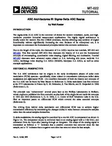
5 SIMULATION AND EXPERIMENTAL RESULTS Simulation results show that the encoder can operate in a wide range of frequencies by adjusting the bias current of the gates. Figure 9(a) shows the maximum frequency of operation of the encoder as a function of the tail bias current of the STSCL gates. Pipelining has helped to improve the powerdelay performance of the circuit as explained in [13]. The bias current of the digital circuit is set to be
A. Tajalli and Y. Leblebici, “Nanowatt range folding-interpolating ADC using subthreshold source-coupled circuits,” in J. of Low-Power Electronics, 2010. RESTRICTIONS APPLIED. FOR ACADEMIC USE ONLY.
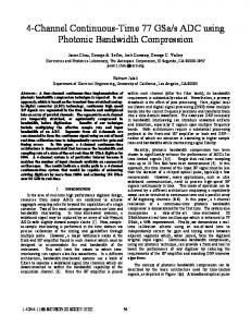
a fraction of the bias current of the analog section, therefore, a separate controlling unit is avoided. The encoder circuit consists of 196 STSCL gates, operating in pipeline mode. Figure 9(b) illustrates the minimum supply voltage of digital part with respect to the gate tail bias current. For tail bias currents below 10nA, the supply voltage could be reduced below 0.5V. When tail bias current is below 1nA, the supply voltage can be reduced to 0.35V, maintaining a signal swing of 200mV. However, as mentioned earlier, the choice of the supply voltage level does not have any impact on the operation speed and the noise margins.. Figure 10 shows the photomicrograph of the prototype test chip fabricated in 0.18μm CMOS technology. The total active area of the circuit is 0.6mm2. The bias current of the analog and digital parts are controlled externally with respect to the sampling frequency. The sampling frequency of the proposed ADC can be adjusted from 500S/s to 80kS/s where the power consumption is scaling proportional to the sampling frequency from 17nW (digital part: 1nW) to 1.9μW (digital part: 100nW) with ENOB of 6.7. Figure 11 shows the power scalability of the ADC with respect to the sampling frequency. The adjustment of power dissipation with respect to sampling frequency is achieved by changing the reference bias current. As can be seen, the power dissipation of digital part is negligible with respect to the total circuit power consumption. To obtain the same performance using CMOS logic circuits, a separate precisely controlled supply voltage would be needed. Meanwhile, the measured spectrum of the output signal at fs = 409.6 Hz has been shown in Figure 12. Figure 13 shows the measured integral non-linearity (INL), and differential non-linearity (DNL) of the proposed FAI ADC which are 1.0LSB and 0.4LSB, respectively. As both digital and analog parts are based on differential topology, the sensitivity of the circuit to supply voltage variations is very low, and can be changed from 1.0V to 1.25V. An internal replica bias circuit controls the biasing condition of different parts of the circuit to minimize the effect of process, supply voltage, temperature (PVT) variations. A. Tajalli and Y. Leblebici, “Nanowatt range folding-interpolating ADC using subthreshold source-coupled circuits,” in J. of Low-Power Electronics, 2010. RESTRICTIONS APPLIED. FOR ACADEMIC USE ONLY.
6 CONCLUSION An ultra-low-power folding and interpolating ADC with scalable sampling frequency operating in subthreshold region has been introduced. Using current-mode approach, it is possible to have a wide operating range (800S/s to 80kS/s) while the power consumption scales linearly proportional to it (17nW to 1.9μW from 1.2V supply voltage). Completely novel circuit techniques for improving the speed of operation and also reducing the power consumption in comparator circuit and resistor ladder are developed. The active area of ADC is 0.6mm2 and is implemented in 0.18μm CMOS technology. Measurements show that the INL and DNL of the ADC are 1.0 LSB and 0.4 LSB, respectively. The proposed ADC is an example of a mixed-signal integrated circuit in which power consumption of both analog and digital parts can be adjusted proportional to the sampling frequency using a very simple controlling scheme. This concept can be more generalized to more complicated integrated circuits. Acknowledgment
The authors would like to thank M. Beikahmadi, S. Badel. Y. Temiz, V. Majidzadeh, and S. Hauser for their valuable help during the design and test of the circuit.
A. Tajalli and Y. Leblebici, “Nanowatt range folding-interpolating ADC using subthreshold source-coupled circuits,” in J. of Low-Power Electronics, 2010. RESTRICTIONS APPLIED. FOR ACADEMIC USE ONLY.
REFERENCES [1]
M. D. Scott, B. E. Boser, and K. S. J. Pister, "An ultra-low power ADC for distributed sensor networks," in Proc. of European Solid-State Circ. Conf. (ESSCIRC), pp. 255-258, Sep. 2002.
[2]
J. Sauerbrey, D. Schmitt-Landseidel, and R. Thewes, "A 0.5-V 1-μW successive approximation ADC," IEEE J. of Solid-State Circuits, vol. 38, no. 7, pp. 1251-1265, Jul. 2003.
[3]
G. Bonfini, and et al., "An ultralow-power switched opamp-based 10-B integrated ADC for implantable biomedical applications," IEEE Trans. on Circ. and Syst.-I: Regular Papers, vol. 51, no. 1, pp. 174-178, Jan. 2004.
[4]
N. Verma and A. P. Chandrakasan, "An ultra low energy 12-b rate-resolution scalable SAR ADC for wireless sensor nodes," IEEE J. of Solid-State Circuits, vol. 42, no. 6, pp. 1196-1205, Jun. 2007.
[5]
H.-C. Hong and G.-M. Lee, "A 65-fJ/conversion-step 0.9-V 200-kS/s rail-to-rail 8-bit successive approximation ADC," IEEE J. of Solid-State Circuits, vol. 42, no. 10, pp. 21612168, Oct. 2007.
[6]
S. Gambini and J. Rabaey, "Low-power successive approximation converter with 0.5 V supply in 90 nm CMOS," IEEE J. of Solid-State Circuits, vol. 42, no. 11, pp. 2348-2356, Nov. 2007.
[7]
M. van Elzakker, and et al., "A 1.9μW 4.4fJ/conversion-step 10b 1MS/s charge-redistribution ADC," in Proc. IEEE Int. Solid-State Circ. Conf. (ISSCC), pp. 244-245, Feb. 2008.
[8]
D. C. Daly and A. P. Chandrakasan, "A 6b 0.2-to0.9V highly digital flash ADC with comparator redundancy," in Proc. IEEE Int. Solid-State Circ. Conf. (ISSCC), pp. 554-555, Feb. 2008.
A. Tajalli and Y. Leblebici, “Nanowatt range folding-interpolating ADC using subthreshold source-coupled circuits,” in J. of Low-Power Electronics, 2010. RESTRICTIONS APPLIED. FOR ACADEMIC USE ONLY.
[9]
J. van Valburg and R. J. van de Plassche, "An 8-b 650-MHz folding ADC," IEEE J. of SolidState Circuits, vol. 27, no. 12, pp. 1662-1666, Dec. 1992.
[10] R. Y. van de Plassche and P. Baltus, "An 8-bit 100-MHz full-Nyquist analog-to-digital converter," IEEE J. of Solid-State Circuits, vol. 23, no. 6, pp. 1334-1344, Dec. 1988. [11] M. P. Flynn and D. J. Allstot, "CMOS folding A/D converters with current-mode interpolation," IEEE J. of Solid-State Circuits, vol. 31, no. 9, pp. 1248-1257, Sep. 1996. [12] A. Tajalli, Y. Leblebici, and E. J. Brauer, "Implementing ultra-high-value floating tunable CMOS resistor," IET Electronics Letters, vol. 44, no. 5, pp. 349-350, Feb. 2008. [13] A. Tajalli, E. J. Brauer, E. Vittoz, and Y. Leblebici, "Subthreshold source-coupled logic circuits for ultra-low-power applications," IEEE J. of Solid-State Circuits, vol. 43, pp. 16991710, Jul. 2008. [14] A. Tajalli, E. J. Brauer, and Y. Leblebici, "Ultra low power 32-bit pipelined adder using subthreshold source-coupled logic with 5fJ/stage PDP," Elsevier Microelectronics Journal, vol. 40, no. 6, pp. 973-978, Jun. 2009. [15] M. Mizuno, and et al., "A GHz MOS adaptive pipeline technique using MOS current-mode logic," IEEE J. of Solid-State Circuits, pp. 784-791, vol. 31, no. 6, Jun. 1996.
A. Tajalli and Y. Leblebici, “Nanowatt range folding-interpolating ADC using subthreshold source-coupled circuits,” in J. of Low-Power Electronics, 2010. RESTRICTIONS APPLIED. FOR ACADEMIC USE ONLY.
FIGURES AND TABLES
Figure 1. Architecture of a folding and interpolating ADC.
Figure 2. Conceptual diagram to explain the acceptable frequency tuning range. Here, B0 represents the nominal biasing condition and BOPT is the optimum bias point to maximize the performance.
A. Tajalli and Y. Leblebici, “Nanowatt range folding-interpolating ADC using subthreshold source-coupled circuits,” in J. of Low-Power Electronics, 2010. RESTRICTIONS APPLIED. FOR ACADEMIC USE ONLY.
Figure 3. Power-efficient frequency-scaling
Figure 4. Current mode: (a) folder, and (b) interpolator stages. A. Tajalli and Y. Leblebici, “Nanowatt range folding-interpolating ADC using subthreshold source-coupled circuits,” in J. of Low-Power Electronics, 2010. RESTRICTIONS APPLIED. FOR ACADEMIC USE ONLY.
Figure 5. a) High valued load resistance. (b) Decoupling the parasitic capacitance of the well-substrate from output node. (c) Subthreshold pre-amplifier stage, (d) improvement of frequency response through parasitic capacitance decoupling.
A. Tajalli and Y. Leblebici, “Nanowatt range folding-interpolating ADC using subthreshold source-coupled circuits,” in J. of Low-Power Electronics, 2010. RESTRICTIONS APPLIED. FOR ACADEMIC USE ONLY.
Figure 6. Low power resistor ladder implementation: (a) Ideal resistor ladder used to generate reference voltages. (b) high-value resistance based on subthreshold PMOS device, (c) biasing the proposed high-value resistance where the resistivity can be adjusted through IRES, (d) compact resistor ladder sharing the same biasing circuitry for more than one resistance.
A. Tajalli and Y. Leblebici, “Nanowatt range folding-interpolating ADC using subthreshold source-coupled circuits,” in J. of Low-Power Electronics, 2010. RESTRICTIONS APPLIED. FOR ACADEMIC USE ONLY.
Figure 7. Error correction and encoder using pipelined STSCL topology.
Figure 8. Current-mode realization of the majority detector cell.
A. Tajalli and Y. Leblebici, “Nanowatt range folding-interpolating ADC using subthreshold source-coupled circuits,” in J. of Low-Power Electronics, 2010. RESTRICTIONS APPLIED. FOR ACADEMIC USE ONLY.
Figure 9. (a) Simulated maximum operation frequency of the digital section as a function of tail bias current per gate. (b) Simulated minimum required supply voltage for digital part versus tail bias current per gate.
Figure 10. Photomicrograph of the ultra-low-power ADC chip implemented in 0.18μm CMOS technology.
A. Tajalli and Y. Leblebici, “Nanowatt range folding-interpolating ADC using subthreshold source-coupled circuits,” in J. of Low-Power Electronics, 2010. RESTRICTIONS APPLIED. FOR ACADEMIC USE ONLY.
Figure 11. Power dissipation versus sampling frequency
Figure 13. Measured signal spectrum at fs = 409.6 Hz
Figure 12. Measured differential non-linearity (DNL) and integral non-linearity (INL). A. Tajalli and Y. Leblebici, “Nanowatt range folding-interpolating ADC using subthreshold source-coupled circuits,” in J. of Low-Power Electronics, 2010. RESTRICTIONS APPLIED. FOR ACADEMIC USE ONLY.
BIOGRAPHIES Armin Tajalli received the B.S. and M.S. degrees (Hons.) in electrical engineering from Sharif University of Technology, Tehran, and Tehran Polytechnic University in 1997 and 1999, respectively, and the Ph.D. degree from Sharif University of Technology in 2006 (Hons.). From 1998 to 2006 he was with Emad Semicon as a senior analog design engineer. From 2006 he has joined Microelectronic Systems Laboratory (LSM) in Ecole Polytechnique Fédérale de Lausanne (EPFL) working on ultra-low power circuit design techniques. He has received the award of the Best Design Engineer from Emad Semicon, 2001, Kharazmi award on Research and Development, 2002, Presidential award of the best Iranian researchers, 2003, CICC/AMD Scholarship Award, 2009.
Yusuf Leblebici received his B.Sc. and M.Sc. degrees in electrical engineering from Istanbul Technical University, in 1984 and in 1986, respectively, and his Ph.D. degree in electrical and computer engineering from the University of Illinois at Urbana-Champaign (UIUC) in 1990. Between 1991 and 2001, he worked as a faculty member at UIUC, at Istanbul Technical University, and at Worcester Polytechnic Institute (WPI). Since 2002, Dr. Leblebici has been a Chair Professor at the Swiss Federal Institute of Technology in Lausanne (EPFL), and director of Microelectronic Systems Laboratory. He is a coauthor of 4 textbooks, namely, "Hot-Carrier Reliability of MOS VLSI Circuits" (Kluwer Academic Publishers, 1993), "CMOS Digital Integrated Circuits: Analysis and Design" (McGraw Hill, 1st Edition 1996, 2nd Edition 1998, 3rd Edition 2002), "CMOS Multichannel Single-Chip Receivers for Multi-Gigabit Optical Data Communications" (Springer, 2007) and "Fundamentals of High-Frequency CMOS Analog Integrated Circuits" (Cambridge University Press, 2009), as well as more than 200 articles published in various journals and conferences. He has served as an Associate Editor of IEEE Transactions on Circuits and Systems (II), and IEEE Transactions on Very Large Scale Integrated (VLSI) Systems. He has also served as the general cochair of the 2006 European Solid-State Circuits Conference, and the 2006 European Solid State Device Research Conference (ESSCIRC/ESSDERC). He is a Fellow of IEEE and has been elected as Distinguished Lecturer of the IEEE Circuits and Systems Society for 2010-2011.
A. Tajalli and Y. Leblebici, “Nanowatt range folding-interpolating ADC using subthreshold source-coupled circuits,” in J. of Low-Power Electronics, 2010. RESTRICTIONS APPLIED. FOR ACADEMIC USE ONLY.


![Using Production Grade ADC Services to Build Scalable ... - Citrix [PDF]](https://m.moam.info/img/260x300/using-production-grade-adc-services-to-build-scala_64b117bb098a9e06468b45be.jpg)