A 80GHz Voltage Controlled Oscillator With a Negative Varactor in 90nm CMOS Technology Win Chaivipas, Kenichi Okada, and Akira Matsuzawa Dept. Physical Electronics, Tokyo Institute of Technology 2-12-1-S3-27, Ookayama, Meguro-ku, Tokyo 152-8552 Japan. Tel/Fax: +81-3-5734-3764, E-mail: win
[email protected] Abstract— A 80GHz voltage controlled oscillator is presented. A passive impedance transformation enables the transformation of a varactor capacitance into negative capacitance varactor is proposed, partially canceling the capacitance of the differential pair. This enables the transmission line resonator to be longer and have a higher impedance. Design criterion for achieving negative varactor capacitance is also presented, and design issues of millimeter wave voltage controlled oscillators are discussed. The voltage controlled oscillator is fabricated in 90nm CMOS technology and achieves a phase noise of −110dBc/Hz at 10MHz offset with 13mW power consumption from a 1.2V power supply.
I. Introduction Spurred by the possibility of reaching very high data rates at high frequencies, recent interest in the mm-Wave frequency band (30-300GHz) has resulted in a growing research field [1]–[3] to make cost effective integrated millimeter-wave transceivers. Many problems, however, still abound this field as the challenges of designing transceivers at such frequencies bring about various problems negligible at the lower radio frequencies. One of the blocks which poses a challenge is the frequency synthesizer and its important component, the voltage controlled oscillator. In general, millimeter wave voltage controlled oscillaors (VCO) should achieve many characteristics similar to VCOs at lower cellular bands. These include low phase noise, low power consumption, reasonable output power level, reasonable tuning range and a relatively low VCO gain (sensitivity to tuning capacitor) such that when it is used within a PLL the design consideration for the loop filter does not become too stringent to achieve a reasonable spur level. However, all these factors become increasingly difficult at millimeter-wave frequencies. In particular, to provide a low enough vco gain means that a relatively sufficient size varactor and switched capacitors must be used causing an increase in tank capacitance from the switched capacitors, lowering the tank impedance, and making it difficult to guarantee oscillator start-up across process variation. At millimeter-wave frequencies the resonator becomes increasingly sensitive to capacitance, decreasing the tank impedance at a faster rate than at lower frequencies as the capacitance size increases. To counter this, current may be increased, to increase the transconductance of the differential pair, however, this increase in transconductance has limitations, and in order to ensure a reliable start-up, the size of the differential pair must be further
Zin
CL
-KC L
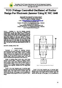
Fig. 1. Equivalent negative capacitance can be seen from end of transmission line.
increased. This increase in the differential pair size, however, also increases its associated parasitic capacitance which may be neglected at lower frequencies, but are significant at millimeter wave frequencies, resulting in diminishing returns. Several methods to try to solve this problem has been proposed including using a sub resonator to partially cancel the effect of the parasitic capacitance [4], and using impedance transformation of an active device [5]. In this paper we introduce a method similar to [5], however, instead of impedance transformation of an active device (differential pair), we show that impedance transformation is also possible with passive devices, in this case the varactor’s capacitance and parasitic capacitance of the output buffer. The advantages are obvious, impedance transformation of the active device means that the extra active device adds more noise into the system, and in addition consumes more power. In addition, transformation of the varactor, and output buffer capacitance means that the varactor and output buffer’s capacitance no longer contributes to the increase of tank capacitance, but in addition cancels out part of the tank capacitance coming from the differential pair. II. Impedance Transformation It is generally known that a transmission line can be used to transform an impedance value. In case of a varactor’s capacitance, the transmission line can be used to transform it into a variable negative capacitance as shown in Fig. 1 The equivalent input capacitance of a capacitor loaded transmission line (Fig. 1) can be approximated from the well known telegrapher’s equation. Zin = Z0
Zl + jZ0 tan βl . Z0 + jZl tan βl
(1)
where Zin , Zl , Z0 , and β are the impedance seen at the input of the transmission line, the load at the end of the transmission line, the characteristic impedance of the transmission line, and
capacitance (fF)
Impedance vs length of Tline
VDD
CL=20f CL=25f
200
T1
VDD
100
T1 X
X' T2
T2
0
VDD
T3
T3
-100 -200 0
Fig. 2.
tail resonator
100 200 300 400 500 length (µm) Fig. 3.
Equivalent capacitance seen from end of transmission line.
the propagation constant respectively. Which can be solved to find the equivalent input capacitance as ( ) Z0 ωCL + tan βl Ceq = Im (2) . ωZ0 (1 − Z0 ωCL tan βl) where the function Im(x) means the imaginary part of x, and variables Ceq and CL , are the equivalent input capacitance seen at the end of the transmission line and the capacitance load at the end of the transmission line respectively. Note that (1) and (2) are the lossless version of the impedance approximation. To find the lossy transmission line version, appropriate changes to be made to (1) and (2) and replace β with γ, the complex propagation constant which includes loss. The equivalent input capacitance is shown in Fig. 2 for values of load capacitances 20fF and 25fF at 80GHz. In general, either one of the following conditions must be satisfied for the capacitance to be seen as negative. Z0 ωCL tan βl > 1
∩
(3)
tan βl < −1 Z0 ωCL
tan βl > −1 Z0 ωCL
Z0 ωCL tan βl < 1.
(4)
∩
where the symbol ∩ means set intersection. As shown in Fig. 2 the impedance transform not only transform the loaded capacitance to a negative value it also amplifies the size of the negative capacitance depending on the length of the transmission line. In general the length of the transmission line should be chosen to give enough negative capacitance but not too much that it is in the highly sensitive zone, in Fig. 2 about 350µm to 450µm is a good area to aim for. Note that this general impedance transformation technique can possibly be used to cancel parasitic capacitance in other places in the circuit without consuming extra power. Other uses can be for example, canceling out the negative MIM
VCO with negative varactor.
capacitors can also be utilized instead of varactors if higher quality factor is needed. III. VCO Architecture The architecture which can utilize the capacitance impedance transformation is shown in Fig. 3. The resonator is a shorted coplanar waveguide with strip ground shield occupied by the bottom metal layer and top layer thick aluminium metal layer utilized for the coplanar signal and ground. The varactor capacitance in parallel with the output buffer’s gate capacitance is placed at the end of the transmission line (coplanar wave guide same as the resonator) as shown. Due to the impedance transformation, the capacitances from the varactor and the output buffer will partially cancel the differential pair’s capacitance allowing the size of the differential pair transistor to be relatively large enabling a reliable start up across process variation. The larger crossed couple pair also allows a larger bias current resulting in a larger output swing and lower phase noise. The single ended equivalent circuit of Fig. 3 is shown in Fig. 4. As shown, the equivalent capacitance consisting of the varactor capacitance and the buffer capacitance is scaled and becomes negative as a result of the impedance transformation resulting from transmission line T2. The transmission line interconnect between the differential pair and point X also results in the slight scaling of capacitor Cdiffpair , the parasitic capacitance of the differential pair. To save area, it is also possible to reduce the length of T2 which results in a larger scaling of capacitor Ceq . If this scaling is too large, the length of transmission line T3 can be increased, to increase the effective size of the differential pair capacitor seen at X. Weather this saves area, or not, however, will depend on the particular layout shape. Note that in scaling the length of T3 the effective negative transconductance will also be larger. A DC blocking capacitor is also used for two purposes.
VDD T1 T3 Ceq=Cbuff+Cvar
T2
X
Cdiffpair
1/-gm
VDD T1 -K1Ceq
Fig. 4.
K 2Cdiffpair
1/-gm’
Output Buffer
Output Buffer
Equivalent circuit of the designed VCO.
First, it allows biasing of the output buffer, second it reduces the change in capacitance seen with the input voltage at high frequencies. At high frequencies of the output buffer’s parasitic gate source capacitance’s change with voltage level becomes significant essentially giving it a varactor like characteristic. Any amplitude modulated (AM) noise then will be converted to (phase modulated) noise through AM-PM conversion just as a varactor. All DC cut capacitors utilize metal-insulator-metal (MIM) capacitors with short finger length to ensure high self resonant frequencies. The capacitors are kept small as parasitic bottom plate capacitance is very significant in adding loss to the system at high frequencies. Lastly, a noise filtering capacitor is inserted to filter up the current source’s noise, and a transmission line is inserted between the current source and the common node of the differential pair resonate with the parasitic capacitance at that node and produce a high impedance at twice the oscillation frequency [6]. The design parameters of the voltage controlled oscillator is summarized in Table I. The minimum characterized varactor size was large, so the AC coupling capacitor served to both enable a different bias current and also decrease the effective value of the varactor so that the varactor’s value is not too large. The chip photo of the fabricated chip is shown in Fig. 5. IV. Measurement The measurement setup of the phase noise is shown in Fig. 6. W-band on wafer probes were used to probe the die directly, while DC probes provides the bias. The output signal is amplified by a W-band amplifier and the power is split into differential signal with a wave guide power divider. The
Fig. 5.
Chip photo.
TABLE I Design Parameters.
Transmission line
Resonator T1 Tail Resonator Cap Resonator T2 Diff. Pair T3 Diff. Pair Current Source Current Mirror Buffer Varactor
width 10µm Spacing 13µm impedance 55Ω length 100µm length 100µm length 300µm length 70µm 1µm/0.1µm x12 10µm/0.5µm x 80 10µm/0.5µm x 20 2µm/0.1µm x 2 12v15fF
signal is then mixed with 2 harmonic mixes to a low IF by a local oscillator provided by the VCO analyzer. The two down converted signals are then input into the VCO Analyzer and the phase noise measured. Figure 7 shows the measured phase noise of the VCO. The VCO achieves better than −110dBc/Hz at 82.5GHz while dissipating 13mW from a 1.2V power supply excluding the buffer’s power. The tuning range varies between approximately 300MHz and 680MHz depending on bias current. The tuning range was smaller than expected due to two facts. First this was the first prototype circuit and accurate models at high frequencies were not available at high frequencies. Second it is speculated that the small capacitors MIM capacitor models,
VCO Analyzer
DC Supply
Power divider
Chip
negative capacitance impedance transformation also allows a larger differential pair to be used to enable a reliable start-up A 82GHz voltage controlled oscillator was fabricated and in 90nm CMOS with this negative varactor property, achieving a phase noise of −110dBc/Hz at 10-MHz offset with 13mW of power consumption. Acknowledgment
Amp
Fig. 6.
Phase noise measurement setup.
Phase noise plot
20 Phase noise [dBc/Hz]
Harmonic mixer
40 60 80 100 120 140 10k 100k 1M 10M Frequency offset oscillation frequency (Hz) Fig. 7.
Measured phase noise. TABLE II
Performance Summary.
Process Oscillation freq. Tuning range Power supply Bias current Power Phase noise Area inc. pads
90nm CMOS 82.8-83.56GHz (680MHz) 300MHz-680MHz 1.2V 10.8mA 13mW −83.2@1 MHz, −109.9@10 MHz 970µm×800µm
used for the DC cut of the varactors, were not accurate at these frequencies. The performance summary is shown in Table II. V. Conclusion In this paper, we propose a millimeter-wave VCO using a passive impedance transformation technique. The impedance transformation technique achieves a negative capacitance without adding noise as does the conventional active impedance transformation technique. The proposed passive impedance transformation allows an oscillator to oscillate at higher frequencies without the added power consumption and noise. The
This work was partially supported by MIC, STARC, and VLSI Design and Education Center (VDEC), the University of Tokyo in collaboration with Cadence Design Systems, Inc and Agilent Technologies Japan, Ltd. References [1] T. Mitomo, R. Fujimoto, N. Ono, R. Tachibana, H. Hoshino, Y. Yoshihara, Y. Tsutsumi, and I. Seto, “A 60-GHz CMOS Receiver Front-End With Frequency Synthesizer,” in IEEE Journal of Solid-State circuits, vol. 43, no. 4, pp. 1030–1037, Apr. 2008. [2] C. H. Doan, S. Emami, D. A. Sobel, A. M. Niknejad, and R. W. Brodersen, “Design Considerations for 60 GHz CMOS Radios,” in IEEE Communications Magazine, Dec. 2004, pp. 132–140. [3] E. Laskin, M. Khanpour, R. Aroca, K. W. Tang, P. Garcia, and S. P. Voinigescu, “A 95GHz Receiver with Fundamental-Frequency VCO and Static Frequency Divider in 65nm Digital CMOS,” in IEEE SolidState Circuit Conference, Feb. 2008, pp. 180–181. [4] J. Chien and L. Lu, “A 40-GHz Wide-Tuning-Range VCO in 0.18-um CMOS,” in IEEE Symposium on VLSI Circuits, Jun. 2006, pp. 178–179. [5] H.-H. Hsieh and L.-H. Lu, “A 63-GHz Voltage-Controlled Oscillator,” in IEEE Symposium on VLSI Circuits, Jun. 2007, pp. 178–179. [6] E. Hegaziand, H. Sjoland, and A. A. Abidi, “A Filtering Technique to Lower LC Oscillator Phase Noise,” in IEEE Journal of Solid-State Circuits, vol. 36, no. 12, pp. 1921–1230, Dec. 2001.