Jul 13, 2009 - ber of output phases, more inverter stages are needed at the cost of reducing the maximum attainable operating frequen- cy. Although a VCO ...
A Quadrature Output Voltage Controlled Ring Oscillator Based on Three-Stage Sub-feedback Loops Lizhong Sun, Tad Kwasniewski and Kris Iniewski" Department of Electronics, Carleton University, Ottawa, ON, Canada *PMC-Sierra, Inc., Burnaby, BC, Canada
ABSTRACT This paper presents a general ring oscillator circuit topology for high speed operation, multiphase output and wide range tuning. The topology use sub-feedback inverters to construct fast loop for long chain ring oscillator to achieve high speed. The operating frequency of the ring oscillator is directly proportional to the transconductance (G,) of subfeedback inverters which can be controlled with an external voltage. Both single-ended and differential controlled voltage and inverter stages can be used. A quadrature output ring oscillator based on three-stage sub-feedback loops is designed and fabricated in a 0.5pm CMOS process for a 1.25GHz clock recovery application. The circuit operates from 400MHz up to 2GHz, and consumes 3mW at 1.25GHz with 3.3V power supply. 1. INTRODUCTION The voltage/current controlled oscillator (VCO/ICO) is considered a critical building block in phase-locked loops, clock recovery circuits and frequency synthesizers. High-frequency and RF VCO can be implemented monolithically as LC oscillators and ring oscillators. Although ring oscillators have poor phase noise characteristics compared to high Q LC oscillators, they have the advantage of a wider range of oscillation and a small die size area. Ring oscillators are particularly attractive for multiphase and quadrature clock signal generation required for many clock recovery circuits and high-speed sampling systems [ 1][2]. The oscillation frequency of conventional ring oscillator is determined by the gate delay of the inverting stages and the number of gates in the oscillator. In order to increase speed, conventional method is to utilize unavoidable parasitic capacitors as reactive elements and minimize all parasitic by using the delay cell circuits with minimum complexity. Some techniques have been developed to circumvent this limitation. One approach utilizes a four stage ring oscillator where the outputs of the circuit are mixed with each other, and twice the output frequency results [3]. Another approach increases the speed by sensing and combining the transition
in a ring oscillator to achieve a period equal to two ECL gate delays [4]. However in both circuits, the number of the multiphase high-speed outputs is limited. To increase the number of output phases, more inverter stages are needed at the cost of reducing the maximum attainable operating frequency. Although a VCO based on two taps delay interpolation was proposed to speed up the circuit [5], the phase relationship between inverter stages is not fixed under control voltage change. In the next section of this paper, a general ring oscillator circuit topology capable of achieving high speed operation and multiphase output is presented. Oscillation frequency formula is developed based on a linearized model. In Section 3 a detailed implementation of the topology is described. A quadrature output ring oscillator based on three-stage subfeedback loops is designed and analyzed. Measurement results are presented and discussed in Section 4.
2. GENERAL TOPOLOGY AND ANALYSIS For a feedback loop with N (odd number) inverter stages cascaded, the oscillation period of the ring is 2 N z d , where zd is the delay of each stage. The minimum delay of each stage depends on the manufacturing process and the size of transistors. The size of transistors affect the delay through its effect on driving strength, self-loading and its effect on loading to the previous stage. The improvement in speed can be obtained by trying different device sizes in a circuit simulator like HSPICE. However the achievable improvement in speed is limited, especially for long chain of ring oscillators. To solve the conflict between speed and multiphase output, we can split the single feedback loop into N interconnected sub-feedback loops. Each sub-feedback loop contains minimum number of inverters that guaranteeing the circuit reliably oscillation (e.g. three stage inverters). The overall oscillation frequency is within the range of frequency for a stand-alone three stage ring oscillator and a N stage ring oscillator depending the control voltage. Thus, large tuning range and high speed operation can be achieved. The phase relationship between any inverter stage keep unchanged due to the symmetrical structure for each switching nodes.
0-7803-5471-0/99/$10.0001999IEEE
11-176
Authorized licensed use limited to: Carleton University. Downloaded on July 13, 2009 at 14:31 from IEEE Xplore. Restrictions apply.
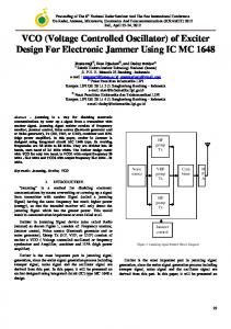
Fig. 1 shows the general topology of ring oscillator with sub-feedback loops. The nodes and their connections have been correspondingly labeled. i is an integer ( 1 2 i < N ) representing the number of inverter delays from where the feedback signal is derived, e.g. when i = 2 we have three inverters in the sub-feedback loops.
from (nt.2)th output node which has a phase delay of 90 degree. Each sub-feedback loop contains three inverters and is established as a fast loop. The phase relationship between each node is also shown in Fig. 3.
D
I 1
I 1
I
I 1 B B
Xi L - - - - - A
Figure 1. General topology of ring oscillator with subfeedback loops Fig. 2 shows the block diagram of a five stage ring oscillator with five voltage controlled sub-feedback loops as example of the topology. Each sub-feedback loop contains three inverters and is established as a fast loop. The main feedback loop (five stages) is the slow loop. The oscillation period can bie understood as the weighted sum of delays through fast loop and slow loop. By controlling the delay of added inverter cell in fast loops, the frequency of oscillation can be tuned in a range of about 5:3 where we define the range of oscillation as f f mrn .
Figure 3. Block diagram of four stage quadrature output differential ring oscillator
To explain the principle behind the improved operating frequency in detail, we model the signal path in the VCO with a linearized circuit, assuming its oscillation amplitude remains small and the waveform is sinusoidal. For a ring oscillator in the steady state oscillation, there is fixed phase relation between stages. The transfer function H ( j w ) of a single stage can be found as
H(jo) =
Figure 2. Bllock diagram of a five stage ring oscillator with sub-feedback loops The topology in Fig. 1 can be extended to a differential structure. Fully differential inverters are used to reduce the sensitivity to power supply fluctuation and substrate noise, which are two of major sources of jitter in high frequency oscillators. Differential architecture also produces 50% duty cycle waveform which is required in many applications. Since each differential delay stage has two outputs, the total number of output is doubled compared to singled-end circuits. Fig. 3 shows the block diagram of the four stage ring oscillator. The inputs of the feedback circuits are derived
vn -
Vn-l
-g,R ( 1 +G,Rcos@)+ j(oRC-G,Rsin@)
(1)
where R and C represent the equivalent output resistance and the parasitic loading capacitance of each stage, respectively. g, and G, represent the transconductance for inverter in main loop and sub-feedback loop, respectively. @ is the phase difference between node (n) and node (n+i). According to Barkhausen criterion of oscillation, the ring oscillator would oscillate if, at wo,the loop has unity voltage gain and phase shift of 2n or multiple 2 n . Thus we have approximate oscillation frequency, oo = [GmRsin@+ tan8( 1 + G,Rcos@)]/RC = tanWRC + koG,/C
and minimum required DC gain
11- 177
Authorized licensed use limited to: Carleton University. Downloaded on July 13, 2009 at 14:31 from IEEE Xplore. Restrictions apply.
g,R
= (/, 1 + G,Rcos@)
2
+ (o,RC- G,Rsin$)2
(3)
T
In (2) k , = sin(i0) + t g 0 . cos(i0). 0 is the phase difference between adjacent nodes (e.g. 0 = 4x13 , for N = 3 and 0 = 6n/5 ,for N = 5 )and we have 9 = iO . From (2), we know that oscillation frequency can be tuned by varying anyone of three parameters: loading capacitance (C), loading resistance (R) and transconductance (Gm). Capacitive tuning has drawback of slowing down the maximum speed of operation. Although resistive tuning based on transistor in triode region can provide a large frequency variation, it causes voltage swing and voltage gain variation. If polysilicon resistors are used as loading to improve linearity, the time constant at the drain of driving transistor does not directly depend on the tail current, thus the tuning range is very small. The sub-feedback loop topology provides an alternative method of frequency tuning. When G, is controlled by an external voltage, the oscillation frequency is directly proportional to G, with a linear slope, which can be understood as changing the effective number of delay stage within the range of three and N ( 3 < N e f f < N ). To achieve the increased oscillation frequency, k , in (2) should be positive. Since 0 is fixed for a given stage number ring oscillator, whether the oscillation frequency is increased or decreased depends on the parameter i which is the number of delay stages from where the feedback signal is derived. Taking a seven stage ring oscillator as an example ( 0 = 8n/7 ), when sub-feedback loops contain three (i=2) or five (i=4) inverters, frequency is increased ( k , > O ) compared to the conventional one. Three stage sub-feedback loop is preferred due to its larger value of k , compared to that for five stage sub-feedback loop. However, when subfeedback loops contain four (i=3) or six (i=5) inverters, frequency is decreased ( k , e 0 ). This can be easily proved with HSPICE time domain simulation.
3. CIRCUITS AND DESIGNS Fig. 4 shows the proposed single-ended implementation example of the topology. M2 and M3 are the drive transistors for common source gain stages. The PMOS current source MI is used as a shared active load. The gate controlled transistor M4 is connected to the source of M, and used as variable resistor. M3 and M4 together provide a voltagecontrolled transconductance G, to the oscillator. Cascoding current source can be used to provide high impedance to buffers the output from power supply VDD,thereby reducing the noise injection from VDDto the output. The use of a current source in the load also prevents an excessive increase of power consumption when operating frequency increases.
1
0
I
1
I
I
vc
Figure 4. A single-ended implementation example of the topology (N=5) Fig. 5 shows a single stage differential circuit which combines inverters for major and sub-feedback loops in block diagram of Fig. 3. The shared resistive load can be implemented with polysilicon layer to reduce l/f noise in active loading and achieve linear symmetrical function. The gatedrain connected MOSFET can be also used as resistive load to save chip size but at the cost of degraded linearity. Frequency tuning is achieved either with I,, controlled with a single-end signal or both I,,, controlled (push-pull) with a differential signal. r - - - - - - - -
, T
1
Figure 5. A single stage differential circuit for block diagram of Figure 3
4. MEASUREMENT RESULTS Several VCO designs were implemented and fabricated in the HP 0.5pm CMOS technology. It is a triple metal, single poly CMOS process allowing a minimum drawn feature size of 0.6pm. VCOl is a single-ended five-stage ring oscillator with sub-feedback loops as shown in Fig. 4. All five stages use the
same device sizes. Fig. 6 shows the measurement results of control voltage to oscillation frequency transfer characteristics. VCOl can operate from 800 MHz to 1.28 GHz corresponding to a control voltage from 0 to 3.3 V. The tuning range is about 500 MHz, which is 62.5% larger than that for conventional five stage ring oscillations (V,=O). The power consumption is 6mW at 1.28 GHz against 5.5mW at the 800 MHz. The proposed circuit is more power efficient since it has lower speed-power product which is simply the product
11-178
Authorized licensed use limited to: Carleton University. Downloaded on July 13, 2009 at 14:31 from IEEE Xplore. Restrictions apply.
of the oscillation period and total power consumption (4.68pJ against 6.87pJ). The measured phase noise at 1.25GHz is lOOdBc/Hz at lMHz offset frequency.
“r
1
0
05
15
1
2
25
M r dV o l eM
3
35
Figure 6. Measurement result of transfer characteristics of vco 1 VC03 is a quadrature output ring oscillator as shown in Fig. 3 and Fig. 5. Gate-drain connected PMOS are used as resistive load to the differential delay cell. Measurement results of control current to frequency transfer characteristics is shown in Fig. 7. The dash curve represents the measurement results when I b , = 0 (conventional four stage ring). The operating frequency range is from 400MHz to 620MHz. The solid curve corresponds to measurement results with I , , = 100pA and I , , used as controlling current. VC03 can operate from 400 MHz to 2 GHz corresponding to I , , variation from 0 tlo 300pA. The tuning range is over lGHz with good linearity. The measured phase noise at 1.25 GHz is 103dBc/Hz at 5MHz offset frequency. Power consumption is 3mW and 4.7’mW at 1.25 GHz and 2 GHz, respectively.
24r
5. SUMMARY
A general ring oscillator topology capable of achieving high speed operation, multiphase output and wide tuning range has been proposed. The topology use sub-feedback inverters to construct fast loop for long chain ring oscillator to achieve high speed. The frequency of the ring oscillator is directly proportional to the transconductance (G,) of subfeedback inverters which can be controlled with an external voltage. Both single-ended and differential controlled voltage and inverter stages can be used. A quadrature output ring oscillator based on three-stage sub-feedback loops is designed and fabricated. The circuit can operate from 400MHz up to 2GHz with a linear voltage control characteristics. The power consumption is only 3mW with a 3.3V power supply. The proposed circuits is suitable for applications in high speed multiphase sampling, clock generation and recovery systems. ACKNOWLEDGMENT The financial support from Motorola Semiconductor, PMC-Sierra, Inc. and infrastructure support from Telecommunications Research Institute of Ontario (TRIO), Canadian Microelectronics Corporation (CMC) and National Science and Research Council of Canada (NSERC) are gratefully acknowledged.
‘ 1
22
OB
o- - - - * O
5
0
1
W
1
5
n
2 M r n C O n d C u m luAl
3
-m
3
5
0
U
X
REFERENCES
B. Kim, D. Helman, and P. Gray, “A 30-MHz hybrid analog-digital clock recovery circuit in 2um CMOS,” IEEE J. Solid-state Circuits, ~01.25,no.6, pp.13851394, Dec. 1990 S.K. Enam and A. Abidi, “NMOS IC’s for clock and data regeneration in Gigabit per second optical-fiber receivers,” IEEE J. Solid-state Circuits, vo1.27, no. 12, pp.1763-1774, Dec. 1992 A. W. Buchwald and K.W. Martin. “High-speed voltage-controlled oscillator with quadrature outputs,” Electron. Lett., ~01.27,no.4, pp.309-310, Feb. 1991 B. Razavi and J.J. Sung, “A 6 GHz 60mW BiCMOS phase-locked loop,” IEEE J Solid-state Circuits, vo1.29, no.12, pp.1560-1565, Dec. 1994 S.K. Enam and A. Abidi, “A gigahertz voltage controlled ring oscillator,” Electron. Lett., v01.22, pp.677-679, June, 1986
I
Figure 7. Measurement result of transfer characteristics of VC03
11-179
Authorized licensed use limited to: Carleton University. Downloaded on July 13, 2009 at 14:31 from IEEE Xplore. Restrictions apply.