A Binary Coding Approach for Combination Networks and General Erasure Networks Ming Xiao
Muriel M´edard
Tor Aulin
Department of Computer Engineering Chalmers University of Technology Gothenburg, 412 96 Sweden
[email protected]
Lab. for Info. and Decision Systems Massachusetts Institute of Technology Cambridge, MA, 02139 USA
[email protected]
Department of Computer Engineering Chalmers University of Technology Gothenburg, 412 96 Sweden
[email protected]
Abstract— We investigate a deterministic binary coding approach for combination networks. In the literature, network coding schemes with large alphabet sizes achieve the min-cut capacity. Here, we propose an approach using binary (GF(2)) sequences instead of going to a large alphabet size. In the encoding process, only cyclic-shifting and XOR operations are used. The encoding complexity is linear with the length of information bits. The transfer matrix is sparse, and the decoder can perfectly decode source information by a sparsematrix processing approach. Our approach does not use any redundant bits, and achieves the min-cut capacity. Further, the code blocks can be produced in a rateless way. The sink can decode source information from any subset of code blocks, if the number of received distinct blocks is the same as that of the information blocks. Thus, we use the code for general networks with erasure channels. The proposed binary rateless codes have quite small overheads and can work with a small number of blocks. With high probability, the codes behave as maximum distance separable (MDS) codes.
I. I NTRODUCTION {a1 , a2 , b1 , b2 }
[I1 , I2 ]
s [I1 ]
# {b , m1 b 1} 2
' $ t1
[I2 ] {a1 ⊕ b1 , ! m2 a2 ⊕ b2 }
%) t2
&# t3
[I1 + I2 ] {a1 ⊕ b2 , " m a2 } 3
"* t4
[I1 + 2I2 ] {a1 , a2 ⊕ b1 }
(+ t5
m4
&$ t6
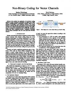
` ´ Fig. 1. A 42 combination network. [·] is the nonbinary solution, I1 and I2 are symbols with the minimum ternary alphabet size. {·} denotes the binary sequence solution. a1 , a2 , b1 and b2 are information bits.
We investigate codes for a special class of networks: combination networks. Though they have a simple structure, This work was supported in part by DAWN: Dynamic Ad Hoc Wireless Networking ARO contract 007625.
the codes capture some essential properties of more general problems. One can always find, for such networks, codes that satisfy the maximum distance separable (MDS) property, namely, the source can be reconstructed from any subset of blocks equal to the number of blocks in the source before coding. Combination networks are akin to the topologies found in storage ! N area " networks (See, for instance, Page 125, [4]). An m combination network [1], [2] is a 3-layer single source multicast network. The first layer is the source node, which has independent messages. The second layer consists of N nodes, where each ! N of" them has one edge connecting to the source. There are m sinks in the third layer. Each sink has m edges connecting to m nodes of the second layer. The combination networks are often used in the literature to show the usefulness of a large alphabet ! size " for codes using a scalar approach, e.g., [3], [5], [6]. A 42 combination network is shown in Fig. 1. Each edge has unit capacity. Here, a unit is in the alphabet size of the network code. The multicasting task requires that both symbols (I1 and I2 ) should be received at six sinks. Clearly, the min-cut between each sink and source is 2. It is shown (e.g., [3], [5], [6]) that the binary coding scheme with the scalar approach cannot achieve the maximal possible flow, which is determined by the min-cut [9], [10]. A minimum ternary alphabet size is used to achieve the min-cut capacity [3], [5]. With an increased N , an even higher alphabet size is used. This is true if codes using the scalar approach are considered. However, if the code with a sequence (vector) approach is used, the situation is different. This is what we shall discuss. If there are only additions (subtractions) in the code, operations in a field of GF(2n ) and n bit sequences (vectors) are the same. They both are n bit-wise operations [12]. A bit-wise operation means an operation only between bits having the same positions in the sequences. However, for multiplication (division), operations on GF(2n ) have much higher complexity than those of n bit-wise sequences. This motivates some earlier work on using a sequence of bits instead of a higher alphabet size. In [5], codes with a binary sequence are used for a special network operating below channel capacity. The codes in [5] use redundancy, which increases with the sequence length. In [11], a random binary code approach is shown to replace a large alphabet size. The approach uses an encoder at the
source, which introduces redundancy. In intermediate nodes, the code performs permute-and-add operations. Though the alphabet size is reduced, a large block length is used to get a low error probability (for error-free channels). The coding scheme proposed in this paper is deterministic, and introduces no redundancy, so that the min-cut capacity can be achieved. The sinks can perfectly recover source information bits for error-free channels. In the presence of erasures, our codes achieve the MDS property. In Section II, we show the coding scheme, and analyze the rank property. In Section III, we propose quasi-systematic codes, and discuss the connection between our codes and array codes. In Section IV, we discuss complexity and block length. In Section V, we investigate a rateless approach for general erasure networks. II. C ODING S CHEME
0 0 M j,i . 0 0 ··· 0 0 0 · · · 0 p×p (2) Each column or row of M j,i has at most one 1, and other elements are zeros. Let mk,t (k, t = 1, · · · , p) be the kth row and tth column element of M j,i , 0 ··· 0 ··· = 0 ··· 0 ···
mk,t !
"
N Without loss of generality, we assume an m combination network as described before. Both N and m are arbitrary positive integers with m ≤ N . Thus, the min-cut between the source and each sink is m. The information bits in the source are put into m sequences. We denote them as I 1 , I 2 , · · · , I m (row vectors). The length of each sequence is p, and p + 1 is a prime. Here we assume that source information bits are long enough to form these sequences. For the jth (j = 1, · · · , N ) output channel, the output bit sequences are encoded by Algorithm 2.1. In this paper, we call a bit sequence output from the source a coded block. For encoding, we only use cyclic-shifting and XOR operations. Both of them have very low complexity and can be easily implemented by a hardware ([12], [15]). We refer to the coding scheme as the binary sequence code.
Algorithm 2.1: (Encoding) 1: Pad-zero: In the end of each I i (i = 1, · · · , m), one zero is appended in sequences. The resulting sequences are Iˆi . 2: Cyclic-shift. For the output to the jth (j = 1, · · · , N ) second layer node, cyclic-shift Iˆi (j − 1)(i − 1) times (bits). The resulting sequence is denoted as e I j,i . 3: Final-bit removal. The final bit of e I j,i is discarded. 4: Binary add (XOR): The output to the jth (j = 1, · · · , N ) second layer node is formed by binary adding all e I j,i (i = 1, · · · , m).
Note that # I j,i has the same length as I i after the final bit is removed. In the encoding process, code blocks are produced in a block-by-block fashion rather than simultaneously. This property will be exploited later for the network with erasure channels. Now, we first analyze some algebraic properties of the code. We denote the coded block (p bits) in the jth second layer as C j . By Algorithm 2.1, Cj = M jI
encoding matrix for the jth second-layer node. M j,i (i = 1, 2, · · · , m) is
(1)
where I = [I 1 , I 2 , · · · , I m ]T is a pm × 1 column vec$tor denoting the source% information bit sequences. M j = M j,1 , M j,2 , · · · , M j,m is a p × pm matrix denoting the
0 ··· 0 ··· ··· 1 0 0 1
0 0 ··· ··· ···
1 0 0 1
··· ···
, 1 t = ((i − 1)(j − 1) + k) mod(p + 1), = 0 otherwise.
(3)
From (3), we can see that the kth row of M j,i is all-zero if ((i − 1)(j − 1) + k) mod(p + 1) = 0. By!the" topology of comN bination networks, a sink z(z = 1, · · · , m ) must connect to m different second-layer nodes z1 , z2 , · · · , zm . The m blocks (sequences) received in the sink z are C z1 , C z2 , · · · , C zm , totaling pm bits. The transfer matrix for the sink z is
Ms,z
M z1 ,1 M z ,1 2 = M zm ,1
M z1 ,2 M z2 ,2 ··· M zm ,2
··· ··· ···
M z1 ,m M z2 ,m . (4) M zm ,m pm×pm
The decoding process is to recover the pm information bits from the received pm code bits, namely,
I T1 C z1 IT Cz −1 2 2 : = Ms,z : C zm I Tm
.
(5)
In the encoding and decoding process, all operations are performed bit-wise. The decoder recovers pm bits from pm received bits. The validity of the code then hinges on the invertibility of Ms,z . To show that Ms,z is invertible, we - with p + 1 rows and p + 1 introduce another matrix M j,i - (m columns. The elements of M j,i # k,t , k, t = 1, 2, · · · , p + 1) are obtained by (3). Since M j,i is a (p + 1) × (p + 1) - has exactly one 1 and matrix, each row or column of M j,i - is a cyclicall other elements are zero by (3). Note that M j,i shifting matrix. A (p + 1) × 1 column vector is cyclic-shifted - . M and M (i − 1)(j − 1) times if multiplied with M j,i j,i j,i have the same elements except in the final row and the final - . column of M j,i Following the notation of [13], [14], we denote σ as the one- = σ (i−1)(j−1)mod(p+1) . time cyclic-shifting matrix. Thus, M j,i - is an identity matrix. If (i − 1)(j − 1)mod(p + 1) = 0, M j,i In the following, we shall omit the mod(p + 1) operation and use (i − 1)(j − 1). Then,
M s,z
!
=
M M ··· M z1 ,1 z1 ,2 z1 ,m M z2 ,1 M ··· M z2 ,2 z2 ,m ··· M M · · · M z ,1 z ,2 zm ,m 0 m (z −1) m σ σ 1 · · · σ (z1 −1)(m−1) σ 0 σ (z2 −1) · · · σ (z2 −1)(m−1) ··· σ 0 σ (zm −1) · · · σ (zm −1)(m−1)
.(6)
- is a (p+1)m×(p+1)m matrix. σ 0 is a (p+1)×(p+1) M s,z identity matrix. Without loss of generality, we assume 1 ≤ z1 < z2 < · · · < zm ≤ N . Lemma 1. The rank of M s,z is pm + 1. Proof: Owing to space limitations, we only give an outline of the proof. The circulant matrix σ k is associated with a polynomial xk , which is over a ring of binary polynomials modulo Rp+1 = xp+1 − 1. M s,z is associated with a Vandermonde polynomial matrix with a nonzero determinant to Rp+1 /(x − 1). We define an auxiliary vector V j = {V j,0 , V j,1 , · · · , V j,m−1 }, j = 0, · · · , m − 2. The subvectors V j,k , (k = 0, · · · , m − 1) are 1 × (p + 1) row vectors. V j,k = {1, 1, · · · , 1} if k = j, or k = j + 1, otherwise V j,k = {0, 0, · · · , 0}. The dimension of span{V j |j = 0, 1, · · · , m−2} - = span{V |j = is m − 1. It can be shown the kernel of M s,z j 0, 1, · · · , m−2}. The proof of this can be found in [13, Lemma 2.2] 1 , [14, Section II], for instance. Thus, the rank of M s,z is pm + 1. Theorem 1. The rank of Ms,z is pm (full-rank). Proof: We add the rows k(p + 1) + n, (n = 1, 2, · · · , p) of M s,z to the rows (k + 1)(p + 1) for each k = 0, 1, · · · , m − 1, i.e., we add all rows (except the final row) of the (p + 1) × m(p + 1) matrix [σ 0 , σ (zk −1) , · · · , σ (zk −1)(m−1) ], (k = 1, · · · , m) to their final rows. The resulting matrix is denoted - . Since there is exactly one 1 in each column of σ j for M 1 any j, there is exactly one 1 in each column of the matrix [σ 0 , σ (zk −1) , · · · , σ (zk −1)(m−1) ]. Then, the (k + 1)(p + 1)th - are all-one for k = 1, · · · , m. M - also has rank rows of M 1 1 - . pm+1 since we only perform row transformations from M s,z Then, we remove these m all-one rows and get a pm×(p+1)m - . The rank of M - is at most one less than that of matrix M 2 2 - is pm. M1 . Since M2 has pm rows, the rank of M 2 - . Now we repeat the above procedure for the columns of M 2 - , there In the columns k(p+1)+n, (n = 1, 2, · · · , p+1) of M 2 is exactly one 1 for each row for each k = 0, 1, · · · , m−1. We add the columns k(p+1)+n, (n = 1, 2, · · · , p) to the columns (k + 1)(p + 1) for k = 0, 1, · · · , m − 1, and obtain a matrix - . The columns (k+1)(p+1), (k = 0, 1, · · · , m−1) of M M 3 3 - has rank pm (the same rank as M - ). are all-one columns. M 3 2 - , Then, we remove these all-one columns and get a matrix M 4 which has the same rank as M3 . The reason is follows: all - are (p + 1) × (p + 1) identity M , (k = 1, · · · , m) of M zk ,1
s,z
1M f s,z is slightly more general than the parity check matrix in [13], but there is no difference with the same proof technique of [13].
matrices. Thus, the submatrices composed of the pk + 1-topk + p rows (k = 0, 1, · · · , m − 1) and of the 1-to-p columns - are also p × p identity matrices. Note that M - is the of M 4 4 matrix Ms,z with k(p+1), (k = 1, · · · , m) rows and columns being removed. Thus, the all-one column can be rebuilt in M 4 by adding the first p − 1 columns to the pth column. M4 has - . One may show that M - = M . the same rank as M 3 4 s,z Hence, Ms,z has rank pm. Q.E.D. III. Q UASI -S YSTEMATIC C ODES AND C ONNECTION WITH A RRAY C ODES
In addition to the coded blocks produced by Algorithm 2.1, our codes can also use uncoded blocks directly. For this, up to m − 1 uncoded blocks can be output without encoding. Other N − m + 1 blocks are formed by Algorithm 2.1. Any m of N blocks can reproduce m information blocks. For convenience, we call the codes using uncoded blocks as quasi-systematic codes. We call the coded blocks from Algorithm 2.1 as nonsystematic blocks, and the codes only using nonsystematic blocks as nonsystematic codes. The transfer matrices for the quasi-systematic codes are 0 ··· U z1 · · · 0 ··· 0 U zk ··· 0 , Ms,s = M z ,1 M z ,2 · · · M zk+1 ,m k+1 k+1 ··· M zm ,1 M zm ,2 ··· M zm ,m (7) where U z1 , · · · , U zk are p×p identity matrices. k is an integer with 0 ≤ k < m. In Ms,s , k upper identity matrices are for uncoded blocks, and m − k bottom rows of submatrices are for nonsystematic blocks. The nonsystematic part of Ms,s requires the first column of submatrices to be identity matrices for full-rank. Then, identity matrices for uncoded blocks cannot appear in the left of Ms,s . Hence, there are at most m−1 uncoded output blocks. Ms,s is alike to the parity matrix of binary MDS array codes, e.g., [14], [15]. We use it as the generator matrix. Thus, our quasi-systematic codes are similar to the dual code of array codes. Array codes are systematic codes. There is no limitation on the number of systematic blocks for array codes (Assume the block length p is large enough). However, the number of parity blocks of array codes (k in Ms,s ) is small. At most eight parity blocks is used in [15]. To produce an arbitrary number of parity blocks for MDS array codes is still an open problem e.g., [14], [15]. Thus, for a given number of systematic blocks, MDS array codes cannot have an arbitrary number of output blocks. For this reason, array codes cannot be used for combination networks, which may have many second-layer nodes (output blocks). Assuming the block length p is large enough, there is no limitation on the number of output blocks of our codes for a given number of information blocks. However, there are limitations on the number of uncoded blocks if we output them directly and keep the MDS property (to be discussed later). Similar to those on parity blocks for array codes, there
are two constraints on uncoded blocks of our codes: First, m (the min-cut and the number of information blocks) might not be arbitrarily large when we use quasi-systematic codes. A large m needs very complex verification on p. For a network with small m (e.g., topologies of some storage devices), there is a significant benefit to use quasi-systematic codes since it can greatly reduce encoding and decoding complexity. Second, there is a constraint in the code length p. For quasi-systematic codes, not all primes (minus one) can be used as code lengths for m > 3. The constraints are similar to those of parity check matrices of array codes in [15] (Table I). Under the constraints, we can show that Ms,s is full-rank using approaches similar to Lemma 1 and Theorem 1. Note that for nonsystematic codes, both constraints do not exist for our codes. IV. C OMPLEXITY AND C ODEWORD L ENGTH D ISCUSSION In Algorithm 2.1, m # I j,i s with the length p bits are added. Thus, p(m − 1) ≈ n (for a large m) XORs are used for each code block, where n = pm is the number of information bits. The encoding complexity is linear with the number of information bits. No matter how large the encoding matrix Ms,z is, there are at most m 1s in each row or each column, and other elements are zeros. Then, Ms,z is a sparse matrix. The decoding process can be finished in O(n2 ) binary operations using the approach in [16]. The complexity is the same as those in [11]. Yet, our codes are deterministic and zero-error (for error-free channels). The analysis is for nonsystematic codes. Quasi-systematic codes have lower complexity. Since σ is a (p + 1) × (p + 1) circulant matrix, σ k+p+1 = k - , σ for any 0 ≤ k ≤ p + 1. For the transfer matrix M s,z (z −1)(k−1) i each submatrix M = σ must be different for zi ,k different zi and any given k ≥ 2. Then, we have p + 1 ≥ N.
(8)
Thus, the block length adds a constraint on the number of distinct blocks. Since N ≥ m, we can get p ≥ m − 1. When using the code with a large alphabet size, a mapping from binary bit groups to code symbols is necessary. We assume that the length of these bit groups is D. The alphabet size is 2D . To study the length of our codes, it is interesting to compare D and p. In [5], √ it is shown that the alphabet size is lower bounded by O( Z), where Z is.the number of sinks. In [7], it is shown that an alphabet size 2Z − 74 is sufficient. Then, !N " D = 0.5 log2 (2Z − 74 ). networks, Z = m . !NFor " combination N m m Thus, D = 0.5 log2 (2 m − 74 ). Since ( N ) ≤ Z ≤ ( e) , m m D ≈ C1 m, where C1 is determined by the ratio of N and m. When m ≈ N/2, D ≈ 0.5N , and p ≈ 2D. The result is for the nonsystematic codes, quasi-systematic codes have m − 1 more blocks. Then, p + m ≥ N . p ≈ D for m ≈ N2 . More generally, if we assume N = C · m, where C is a N positive constant, then D ≈ 2C log2 C for a nontrivial N . p = N − m = N (1 − 1/C) (or p ≈ N for nonsystematic codes). Thus, when C is not very big, p is comparable to D. We use the example in Fig. 1 for illustration. For m = 2, we use a quasi-systematic code. Since N = 4 and N − m =
2, p = 2 is enough to meet the multicast task and achieve min-cut capacity. Thus, we divide the source information bits into 2-bit groups. Since m = 2, we denote them as A = {a1 , a2 } and B = {b1 , b2 }. Then we can denote the source information as I = [A, B]T . First, we send B to the node m1 . Then, we produce nonsystematic blocks for m2 , m3 and m4 with Algorithm 2.1. The encoding matrices between the intermediate nodes m1 , m2 , m3 and m4 are, respectively, / 0 / 0 0 0 1 0 1 0 1 0 T1 = ,T2 = , 0 0 0 1 0 1 0 1 T3 =
/
1 0
0 1
0 0
1 0
0
,T4 =
/
1 0
0 1
0 1
0 0
0
.
(9)
Note that we show the transfer matrices just for the purpose of analysis. In the encoding process, there is no any matrix multiplication. The block sent to the second-layer node mi is C i = T i I. The block has a length of 2 bits. It is easy ! " to verify that any two-matrix combination (in the form TT i , i '= j) j of them has rank 4 (full-rank). Thus, all sinks can recover 4 information bits from two blocks, which are received from two second-layer nodes. The coding scheme achieves the min-cut capacity 2. The output blocks are also shown in Fig. 1. For this example, we can also see p = D when m = 0.5N . V. R ATELESS A PPROACH FOR G ENERAL N ETWORKS WITH E RASURE C HANNELS We have shown that the sink can recovery source information from any of the m distinct received blocks, which is a subset of transmitted blocks. This property actually features a MDS property when the codes are used for block erasure channels. Specifically, the source produces N blocks with m information blocks and send them to a network with erasure channels. Here, the erasure channel means that a transmitted block is either received by the sink without any error or lost totally. The erasure can be caused by, for example, an intermediate node memory overflow or a physical-layer decoding error due to wireless interference or channel noise etc. On receiving any m blocks of them, the sink can successfully decode m information blocks. The MDS property motivates us to use our codes for networks with erasure channels. The network is general and is not limited to combination networks. Operating in a rateless fashion, fountain codes [17], [18] are excellent block erasure-correction codes. They use very little or even no feedback. The benefits of fountain codes over traditional erasure-correction codes (such as Reed-Solomon codes), are low-complexity and flexibility in the rate [18]. By [18], this is mainly because fountain codes are binary, and are based on low-density random matrices. The rate-flexible property is because the fountain codes produce output blocks in a rateless fashion. The encoding process can be stopped whenever a termination condition is satisfied. From Algorithm 2.1, the encoding process of our codes can also be stopped after a coded block is produced. Thus, it can also work in a rateless fashion. Motivated by these facts, we use our codes for networks with erasure channels. The code is rateless, binary
and behaves as MDS codes in a very high probability (to be discussed later). The code is given in Algorithm 5.1. Algorithm 5.1: (The
rateless
binary
sequence
code.)
1: Produce and send out code blocks. Using Algorithm 2.1, the
source continuously produces and sends code blocks. One block is sent out immediate after it is produced. The process stops until the termination condition is satisfied. The blocks are marked as B1 , B2 , · · · , up to BN and saved. 2: The sink receiving m blocks checks if m blocks are distinct. If it is, the sink sends back a termination signal to the source and decodes information bits. 3: The termination condition is satisfied if the source gets termination signals from all sinks or time-out. 4: If the block BN is sent out and the termination condition is still not satisfied, the source transmits the block B1 , B2 , · · · . This process repeats until the termination condition is satisfied or time-out occurs.
Here, we use N = p + 1 (assume nonsystematic codes) to denote the number of possible distinct blocks. The sink can successfully decode the source information by receiving m distinct blocks. Thus, the code is MDS before all N distinct blocks are sent out. The code blocks are produced in a blockby-block fashion. The process can be stopped whenever the termination condition is satisfied. The number of transmitted blocks might be much smaller than N . An unlimited number of blocks can be sent out, though only N of them are distinct. Thus, the code is rateless. In Algorithm 5.1, the source has to retransmit the sent blocks when all distinct blocks are already sent out and the termination condition has not been satisfied yet. This will degrade the system efficiency, and the code will lose the MDS property. Now, we analyze the probability of this event. For convenience, we call it an error, though it is not really a decoding error, and only degrades the system efficiency. Assume that there is one sink. The source has to resend transmitted blocks only if N distinct blocks are transmitted and fewer than m blocks are received by the sink, i.e., more than N − m blocks are lost. The probability of this error is / 0 N 1 N i " (1 − ")N −i (10) PE = i i=N −m+1
where " is the source-to-sink erasure probability. PE decreases with ". For given m, PE also decreases with increasing N . PE is very small for nontrivial N and m. For example, if " = 0.1 and p = 52 (N = 53), and m = 20 (totaling 1040 bits), PE = 1.7 × 10⁻²¹ . If there is more than one sink, e.g., T sinks with the error probability PE1 , PE2 , · · · , PET , PE = max{PE1 , PE2 , · · · , PET }, since sinks receive blocks in a parallel way. Thus, we can ignore the situation when the source has no unsent block. Moreover, from this example, we can see that the number of information blocks can be quite small. This is different from the codes based on sparse random matrices. These codes normally use a large number
of blocks (denoting a large random matrix) to increase the probability of successful decoding. Another benefit of our code is small overhead since it behaves like MDS codes with a high probability. Yet, the code has quadratic decoding complexity. In the above analysis process, we do not assume any limitation on the network model. Thus, it can be used in general networks (including combination networks and unicast networks as special examples). VI. C ONCLUSIONS We propose a binary network coding approach for combination networks. The codes use bit sequences instead of large alphabet-size symbols. They achieve the min-cut capacity. The encoding complexity is linear with the number of information bits, and decoding complexity is quadratical. The code block can be produced in a rateless fashion. The codes have the MDS property with a high probability for erasure channels. These properties motivate us to use codes for general networks with erasure channels. The overhead is quite small and the code can be used for a small number of blocks. Possible directions for future work are a further investigation of using uncoded blocks, and applications for storage area networks [4]. A better decoding approach is another direction for future work. R EFERENCES [1] C. K. Ngai, and R. W. Yeung, “Network Coding Gain of Combination Networks,” In Proc. IEEE Info. Theory Workshop, pp. 283-287, San Antonio, USA, Oct. 2004. [2] Z. Li, B. Li, and L. Lau, “On Achieving Maximum Multicast Throughput in Undirected Networks,” IEEE Trans. on Inform. Theory, vol. 52, pp. 2467-2485, June 2006. [3] R. W. Yeung, S. Y. R. Li, N. Cai, and Z. Zhang, “Network Coding Theory,” Foundation and Trends in Communications and Information Theory, now Publishers, Hanover, MA. USA, 2006. [4] R. Thornburgh, and B. Schoenborn, Storage Area Networks, Prentice Hall, 2001. [5] A. Rasala-Lehman, Network Coding, Ph.D thesis, MIT, Feb. 2005. [6] C. Chekuri, C. Fragouli, and E. Soljanin, “On average throughput and alphabet size in network coding,” IEEE Trans. on Inform. Theory, pp. 2410 - 2424, June 2006. [7] C. Fragouli, and E. Soljanin, “Information Flow Decomposition for Network Coding,” IEEE Trans. on Inform. Theory, Mar. 2006. [8] R. Ahlswede, N. Cai, S.-Y. R. Li and R. W. Yeung, “Network information flow,” IEEE Trans. on Inform. Theory, pp. 2410-2424, June 2006. [9] S. Li, R. W. Yeung and N. Cai, “Linear network coding,” IEEE Trans. on Inform. Theory, vol. 49, pp. 371-381, Feb. 2003. [10] R. Koetter and M. M´edard, “An algebraic approach to network coding,” IEEE/ACM Trans. on Networking, vol. 11, pp. 782-795, Oct. 2003. [11] S. Jaggi, Y. Cassuto, and M. Effros, “Low Complexity Encoding for Network Codes,” In Proc. IEEE Int. Sym. on Info. Theory, July 2006. [12] S. Lin, and D. Costello, Jr. Error Control Coding, Prentice Hall, 2004. [13] H. Fujita, and K. Sakaniwa, “Some Classes of Quasi-Cyclic LDPC Codes: Properties and Efficient Encoding Method,” IEICE Trans. on Fundamentals, vol. E88-A, No. 12, Dec. 2005. [14] W. Tan, and J. Cruz, “Array Codes for Erasure Correction in Magnetic Recording Channels,” IEEE Trans. on Magnetics, vol. 39, Sep. 2003. [15] M. Blaum, J. Bruck, and A. Vardy, “MDS Array Codes with Independent Parity Symbols,” IEEE Trans. on Info. Theory, vol. 42, No. 2, Mar. 1996. [16] D. Wiedemann, “Solving Sparse Linear Equations Over Finite Fields,” IEEE Trans. on Info. Theory, vol. 32, No. 1, Jan. 1986. [17] J. Byers, M. Luby, M. Mitzenmacher, and A. Rege, “A Digital Fountain Approach to Reliable Distribution of Bulk Data,” In Proc. ACM Sigcomm’ 98, pp. 56-67, Vancouver, Canada, Sep. 1998. [18] M. Mitzenmacher, “Digital Fountains: A Survey and Look Forward,” In Proc. IEEE Info. Theory Workshop, San Antonio, USA, Oct. 2004.