control lead to the node voltages given in Table I. They result from the following description of the circuit operation: ⢠During Φ = 0, MP4 will be OFF because its ...
D. Aksin, M.A. Al-‐Shyoukh, F. Maloberti: "A Bootstrapped Switch for Precise Sampling of Inputs with Signal Range Beyond Supply Voltage"; Proc. of the IEEE Custom Integrated Circuits Conference, CICC 2005, San Josè, 21 September 2005, pp. 743-‐746. ©20xx IEEE. Personal use of this material is permitted. However, permission to reprint/republish this material for advertising or promotional purposes or for creating new collective works for resale or redistribution to servers or lists, or to reuse any copyrighted component of this work in other works must be obtained from the IEEE.
IEEE 2005 CUSTOM INTEGRATED CIRCUITS CONFERENCE
A Bootstrapped Switch for Precise Sampling of Inputs with Signal Range beyond Supply Voltage Devrim Aksin∗‡ , Mohammad A. Al-Shyoukh† , and Franco Maloberti§ ∗
Custom Mixed Signal Group, Texas Instruments Inc., Dallas, TX, USA Mixed Signal Automotive Group, Texas Instruments Inc., Dallas, TX, USA ‡ Department of Electrical Engineering, University of Texas at Dallas, Dallas, TX, USA § Department of Electrical Engineering, University of Pavia, Pavia, Italy †
Abstract— Bootstrapped switches are used in a variety of applications including DC-DC converters, pipelined analog-todigital converters and high voltage switches and drivers. Current work on highly integrated power management applications often requires the ability to measure voltage quantities that exceed the supply voltage in magnitude. This is primarily due to a basic need to maximize efficiency by running the power management IC on as low supply voltage as possible, while still maintaining the ability to sample and measure quantities from the surroundings that could well exceed the battery voltage. In this paper a new bootstrapped switch is presented. The switch enables the precise sampling of input signals well greater than the chip supply voltage with no static power consumption, and without activating on-chip parasitic body diodes. The bootstrapped switch, presented here, is designed to sample an input signal with a 0-5.5 V range at a supply voltage of 2.75 V. Measurement data shows functionality for a 0-6 V input signal range with a supply voltage as low as 1.2 V.
I. I NTRODUCTION Bootstrapping circuits are used in power management systems and analog-to-digital converters [1], [2], [3], [4]. In power management systems, DC-DC converters often employ bootstrapping techniques to drive the high-side (HSD) switch [5]: both high-side and low-side devices are often implemented with drain extended or DMOS N-channel transistors. The driving of the HSD switch requires using a voltage higher than the supply thus requiring the bootstrapping of the gate control. In ADCs, high-speed pipelines must sample the input signal within a very short time and must ensure an accurate charging of the sampling capacitor. The function is properly realized with bootstrapped switches that are used instead of complementary transistor switches. The result obtains a faster operation with smaller transistors and better-controlled clockfeedthrough. Bootstrapped switches are highly effective in terms of power consumption and require no static current consumption to function. The power losses are only dynamic losses that occur during switching and are due to two contributions: the shoottrough current that occurs when the logic gates controlling the switch’s gate change their logic state, and the power required to charge and discharge capacitive nodes of the switch. The
0-7803-9023-7/05/$20.00 ©2005 IEEE.
use of an effective switch with a small parasitic capacitance reduces both terms. Recent power management solutions often integrate on the same chip multiple switched-mode regulators, multiple lowdropout regulators, voltage references, low-power low-speed SAR ADCs, digital control cores, and serial interface units. The solutions should be able to share resources (voltage references, current references, etc.) among different sections of the chip thus obtaining optimum power efficiency with low power losses during the sleep mode. Normally the shared resources require being active during the sleep or low power modes. The ADC is one of the shared resources and is typically a very low power component used to supervise and monitor onchip and off-chip voltages. The architecture normally used is a multi-channel SAR ADC. Advanced power management systems require proper operation maintaining all functionality with a wide range of supply battery voltages. Namely, the ADC is required to operate even with very low supply voltages and is also required to precisely measure off-chip voltages that can be significantly higher than the used on-chip supply. The above-described situation is challenging not only for the special techniques required for level-shifting of the high-voltage to be measured but also for the need to ensure that no on-chip parasitic diode is forward biased under any condition. Moreover, in order to have a proper sampling the switches must be turned on independent of the difference (sometimes positive) between input and supply voltage. This paper presents a bootstrapped switch to be used for sampling input signals with a range exceeding the supply voltage [6]. The switch enables a precise input sampling without requiring extra power consumption. The proposed circuit is implemented using a conventional CMOS technology and does not require special technology steps or extra masks. The reliability and the lifetime of the entire circuit are not affected by the high-voltage operation of the proposed circuit. This work is divided into four sections. After this introduction, section II reviews commonly used bootstrap switches and discusses features and limitations when the bootstrap switch is used for voltages surpassing the supply. Section III describes
26-3-1
743
Vdd
MN8
MN9
ĭ
MN10 MN5
N7
MN6
MP1
N3
N8
N5
ĭ
MP2 N4 C1
C2
C3 MN4
N1
MN3
MN2
N6
MN1
N2
ĭ
OUT IN
MN7
(a) ĭ
Vdd
N4
MP2 N+
P+
P+
NWELL P- SUB
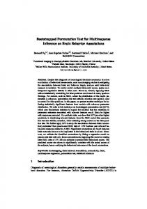
(b) Fig. 1. Conventional Bootstrap Switch (a) Circuit Schematic (b) Cross Section of MP2 showing Parasitic Body Diode
the proposed solution. Section IV is on simulations, circuit implementation and experimental results. Section V is on conclusions and discusses the possible uses of the obtained results. II. C ONVENTIONAL B OOTSTRAP S WITCH The most widely used bootstrapped switch in ADC applications [1], [2], [3] is shown in Fig. 1. The transistor MN1 achieves the switch and the remaining part of the circuit serves to generate a gate voltage that is shifted up by MN2, C3 and MP1 with respect to the input voltage. The output of the boosted switch charges the sampling capacitor in ADCs. The voltage across C3 does not exceed the supply so that the driving voltage of the switch transistor is not larger than the supply. Thus, the stress of the gate oxide is within the limits as required by reliability. The use of the circuit in Fig. 1 with input voltages larger than the supply is not possible. P-channel devices cannot handle a voltage higher than its well bias. If the source (or drain) - well diode is forward biased a large current flows and possibly permanently damages the circuit. The P-channel device of Fig. 1 which will end up with an improperly biased well is MP2. When Φ is high MN4 goes ON and applies the input voltage to the drain of MP2. For an input voltage higher than the well voltage, it would be necessary to automatically switch the well bias to the higher voltage with a complication of the circuit and problems due to the bias switching transient [7].
744
III. P ROPOSED B OOTSTRAP S WITCH Fig. 2 shows the proposed bootstrap switch. The circuit requires only one clock cycle to reach the steady-state operation as it is for the bootstrap switch mentioned above. In the steadystate C1, C2, and C3 are charged at Vdd . These capacitors are used to boost the transistors MN5, MN6 and the switch. The phase Φ controls the operation of the circuit. Namely, when Φ is high the switch is on; when Φ is low the switch is off. The steady-state voltages of the used capacitors and the phase control lead to the node voltages given in Table I. They result from the following description of the circuit operation: • During Φ = 0, MP4 will be OFF because its Vgs = VN 2 − VN 3 = 0, while its drain is at VN 1 = 0 • During Φ = 0, MP3 will be ON because its source is at VN 5 = 2Vdd while its gate is at Vdd which will charge N4 to 2Vdd from the charge stored on C1. • During Φ = 1, MN2 starts charging N1 until N1 reaches Vdd −Vtn , where Vtn is the threshold voltage of an NMOS device. After that MN2 turns OFF because N1 goes to a value above Vdd and because there is no longer enough gate overdrive. After that point the circuit works such that the path through MP4 takes over and drives N1 to Vdd + Vin . • During Φ = 1 and for Vin < Vtp , where Vtp is the threshold voltage of a PMOS device, MP4 starts by being OFF because its Vgs = Vin < Vtp (VN 3 = Vdd + Vin while N2 stays at Vdd because of C4). MN13 will be turned ON pulling N2 to Vin which will turn ON MP4 because Vgs of MP4 becomes equal to Vdd now. As MP4 turns ON the positive feedback loop provided by MN14 and N1 will further connect N2 to Vin through MN14. • During Φ = 1 and for Vin > Vdd − Vtn , MN13 will always be OFF because its Vgs < Vtn (its gate is at Vdd , its source is at Vin > Vdd − Vtn , while its drain is at Vdd or Vin ). As N3 gets pushed to Vdd + Vin , the voltage on N2 (initially a floating node charged to Vdd ) will be determined by the capacitive division between C4 and the gate-source parasitic capacitance associated with MP4. By increasing the size of C4, we guarantee that there is enough gate overdrive for MP4 after the capacitive division. This will guarantee that MP4 will turn ON and start charging N1, and the positive feedback through MN14 will further guarantee that N2 is charged to Vin • During Φ = 1 and for Vtp < Vin < Vdd − Vtn , the switch operates according to a mix of the two cases described above. The above description and the voltages given in Table I show that in any step of operation and under any condition all the parasitic diodes are reversely biases. Thus the circuit enables switching even if the input voltage is larger than the used supply. IV. I MPLEMENTATION AND R ESULTS The proposed bootstrapped switch was integrated in a 0.35 µm twin-well technology. The transistors MN10 and
26-3-2
MN1
IN MP1
MP2
MN7
MN8 N7
N8
Vdd
MN5
OUT
N1
MN6 MN12
N5
MN2
N6 MP3
C1
C2
N4
C3
MN13
N3
MN11
MN14
N1
N2
C4 MN9
ĭ
MN10
ĭ MN3
MN4
Fig. 2.
Node
Φ=0
Φ=1
Φ N1 N2 N3 N4 N5 N6 N7 N8
0 0 Vdd Vdd 2Vdd 2Vdd Vdd Vin 0
Vdd Vdd + Vin Vin Vdd + Vin 0 Vdd 2Vdd 0 Vin
Proposed Bootstrapped Switch
TABLE I S TATE OF THE N ODES AT Φ = 0, AND Φ = 1
MN4, which undergo the greatest oxide stressing, were implemented as thick oxide devices, made available by the used technology. However, the thick oxide option is not a limit to the general use of the proposed circuit. With digital CMOS technologies that do not have thick oxide devices MN10 and MN4 can each be replaced by a series pair of normal transistors and obtain good reliability [1]. The bootstrapped switch is part of the input stage of an ADC with input range exceeding the supply voltage. A standalone version is also incorporated in the chip for characterization purposes. Fig. 3 shows the simulated gate driving voltage as a function of the input voltage. Vdd is equal to 2.75 V and the input range is from 0 to 5.5 V (2Vdd ). Observe that the driving voltage is slightly less than Vdd for low input signals and drops by just about 200 mV when the input is almost twice the supply voltage. The result makes the switch suitable for high-frequency sampling: the high-driving voltage and its limited drop will determine a small harmonic distortion. The maximum drainto-channel voltage allowed by the process reliability limits the maximum input voltage. With technologies with drainextended devices the design of the switch can be tailored for very high input range operation. Fig. 4 shows the simulated waveforms for an input sine wave with a swing of 0-5.5 V. The
supply voltage is 2.75 V. The gate voltage during the on phase tracks the input signal and is shifted up by approximately 2.75 V. Fig. 5 shows the corresponding measured sampled signal. As expected even if the input goes up to twice the supply voltage the obtained output signal tracks the input signal very well. The nominal supply voltage is 2.75 V. However the circuit can operate with a lower supply voltage. By inspection of the circuit it can be found that the minimum allowed supply is 2Vtn . Measurement results show that the circuit operates properly for a supply voltage as low as 1.2 V. With this supply voltage the switch can work with input signals up to 6 V. Therefore, the obtained maximum ratio of Vin /Vdd is 5. The current through the input generator is less than 1 µA. Therefore, the load to the input is negligible and, obviously, there are no diodes that are forward biased. Fig. 6 shows the microphotograph of the test chip. The active area required for the implementation of the switch was less than 0.008 mm2 . V. C ONCLUSION A new bootstrapped switch capable of operating with an input voltage much higher than the supply voltage has been presented. The operation is obtained thanks to a circuit solution that avoids forward biasing in the diffusion-well junctions. The switch is suitable for many applications, including various data-converter architectures (SAR-ADC, pipeline, etc.) The switch is able to control the output transistor with a Vgs that is almost constant over a wide range of switched voltage. This ensures a low harmonic distortion. Finally, the voltage stress on the transistor gates is well controlled leading to no degradation of the circuit reliability. ACKNOWLEDGMENT The Authors would like to thank Marcus Martins, Ross Teggatz, and John Erdeljac of Texas Instruments for their
26-3-3
745
Gate Drive Voltage vs. Input Voltage
2.7
Gate Drive Voltage Vgs (V)
2.65
2.6
2.55
2.5
2.45 0
1
Fig. 3.
2
3 4 Input Voltage Vin (V)
5
6
Gate Drive Voltage Vgs vs. Input Voltage Vin Fig. 5. Measured Switch Behavior with a dynamically Changing Input Signal
Φ (V)
3 2 1
g
V (V)
0 0 8 6 4 2 0 0
0.1
0.2
0.3
0.4
0.5
0.6
0.7
0.8
0.9
1 −5
x 10
0.1
0.2
0.3
0.4
0.5
0.6
0.7
0.8
0.9
1
V
out
(V)
−5
x 10
5
0 0
0.1
0.2
0.3
0.4
0.5
0.6
0.7
0.8
0.9
1
Vin (V)
−5
x 10
5
Fig. 6. 0 0
Fig. 4. Signal
0.1
0.2
0.3
0.4
0.5
time (s)
0.6
0.7
0.8
0.9
1 −5
x 10
Simulated Switch Behavior with a Dynamically Changing Input
[6] D. Y. Aksin and M. A. Al-Shyoukh, “A bootstrapped switch for sampling inputs with a dynamic range greater than supply voltage,” U.S. Patent Application 60/659,705, Mar. 9, 2005. [7] U. Gatti, V. Liberali, F. Maloberti, and P. O’Leary, “Automatic switching of substrate bias or well bias in CMOS-ICs,” Electronic Letters, vol. 26, no. 17, pp. 1381–1382, Aug. 1990.
useful suggestions, and their support in bringing about a speedy implementation of this work on silicon. R EFERENCES [1] A. M. Abo, “Design for reliability of low-voltage, switched-capacitor circuits,” Ph.D. dissertation, California Institute of Technology, Pasadena, CA, USA, 1999. [2] A. M. Abo and P. R. Gray, “A 1.5-V, 10-bit, 14.3-MS/s CMOS pipeline analog-to-digital converter,” IEEE J. Solid-State Circuits, vol. 34, no. 5, pp. 599–606, May 1999. [3] T. Cho and P. R. Gray, “A 10 b, 20 Msample/s, 35 mW pipeline A/D converter,” IEEE J. Solid-State Circuits, vol. 30, no. 3, pp. 166–172, Mar. 1995. [4] J. Steensgaard, “Bootstrapped low-voltage analog switches,” in Proc. IEEE International Symposium on Circuits and Systems ISCAS, vol. 2, 30 May-2 Jun. 1999, pp. 29–32. [5] S. Finco, P. Tavares, A. C. F. D. Mattos, and M. I. C. Simas, “Power integrated circuit drives based on HV NMOS,” in Proc. IEEE 33rd Annual Power Electronics Specialists Conference, vol. 4, 23-27 Jun. 2002, pp. 1737–1740.
746
Die Photo of Test Chip Containing Proposed Bootstrapped Switch
26-3-4