ELECTRONICS AND ELECTRICAL ENGINEERING ISSN 1392 – 1215 ELEKTRONIKA IR ELEKTROTECHNIKA
2008. No. 1(81)
AUTOMATION, ROBOTICS
T125 AUTOMATIZAVIMAS, ROBOTECHNIKA
A Classification of Flash Evoked Potentials based on Artificial Neural Network V. Raudonis, G. Narvydas, R. Simutis Department of Process Control, Kaunas University of Technology, Lithuania Studentų str. 50, Kaunas, phone: 300296, e-mail:
[email protected]
binary control. When the SSVEP is rising above the upper threshold for the required duration it results in a one control action and when the SSVEP is falling below the lower threshold, a different control action results. If the classifier of a BCI is based-on SSVEP then some aspects must be considered: a useful range for BCI is from 5 to 40 Hz, the blinking frequencies of the stimulator must be such that the visual response must be not in the alpha range activity and the components and the harmonics of the visual response must not overlap. The mentioned conditions reduce the number of the useful frequencies for the commands. We are proposing idea, that the certain sequences of the light impulses (or narrows squares) can be used to increase the number of commands, i.e., the certain light code can be used. Some features can be detected in the brainwave of the visual stimulated person which depends on the used light code. The observation of the certain components in the power spectrum of the measured EEG will not give needed results, because the blink of the stimulators is not periodic. Therefore the flash visual evoked potentials (FVEP) of visual cortex which is induced by OFF-to-ON flash of light source must be analyzed and different methods must be used to recognize the user commands [7]. We are proposing to use the artificial neural network for mentioned task. The paper is divided into three chapters. The first chapter describes electrical activity in the human brain and differences between SSVEP and FVEP. Experiments are presented in the second chapter and the conclusions are presented in the third chapter.
Introduction Visual evoked potentials are significant voltage fluctuations resulting from visually evoked neural activity. Neurons in the visual cortex response to the flickering stimuli at the frequency of the flickering light. There are two types of visual evoked potentials, i.e., transient visual evoked potentials (T-VEP) and steady state visual evoked potentials (SSVEP). The former appears after visual stimulation that stimulates the visual cortex of brain with frequency below 1 Hz and the later appears when the stimulation frequency is above 3.5 Hz. The SSVEP is characterized as an increase in EEG activity at the stimulus frequency [1], [2]. During the ten last years there has been a growing interest in the development of Brain Computer Interfaces. A BCI is a communication system that recognizes human commands from brainwaves only and reacts to them. Several BCI’s based on EEG measurements are presented below. Whereas a BCI is communication system, the information transfer rate is often used for the rating of such systems which describes the transfer of digital information between two reference points [3]. The information transfer rate shows the number of recognized user commands per certain time in this instance. The BBCI (Berlin Brain Computer Interface) was presented by the research team from Fraunhofer FIRST institute at the CeBIT 2006 exhibition in Hanover. With this BCI a disabled person can write words and control the mouse pointer by means of his brain waves [4] [5]. The BBCI detects motor-related EEG changes and uses this information to decide between two alternatives: preparation to move the left hand leads to the first alternative, whereas the intention to move the right hand leads to the second alternative. Grant McMillan et al. presented in year 2000 a BCI that translates steady – state visual evoked potentials (SSVEP) for operating a psychical device [6]. Following researchers engineered a BCI, which transforms the noisy SSVEP into smooth and stable control via thresholds and duration requirements. Two thresholds are used to achieve
Background Brain waves are traditionally classified in different frequency bands in the range from 0.5 Hz to 40 Hz. The emittance of a certain frequency group of brain waves depends on the state of the brain. When the brain is aroused and actively engaged in mental activities, it generates beta waves. These beta waves are of relatively low amplitude, and are the fastest of the four different
31
brainwaves. Beta waves are characteristic of a strongly engaged mind. A person, who is in active conversation or making a speech etc., is in beta frequency range. Alpha represents non-arousal. Alpha brainwaves are slower and have higher amplitude compared with beta brainwaves. A person, who has his eyes closed or meditates, is usually in an alpha state. Opening the eyes then usually causes a blocking of the alpha band and the beta frequencies then become more dominant. The theta brainwaves have greater amplitude and slower frequency than alpha and beta brainwaves. A person, who is daydreaming, is often in a theta brainwave state. It is a state where tasks become so automatic that the human can mentally disengage from them. The process of forming and relating ideas that can take place during the theta state is often free flow and occurs without censorship or guilt. Another brainwave state is delta. It is a state where the brainwaves are of the greatest amplitude and slowest frequency. When a human is in deep dreamless sleep, he is in the slowest frequency range (0.5 – 3 Hz). In summary, there are four brainwave states ranging from the high amplitude, low frequency delta to the low amplitude, high frequency beta. These brainwaves are emitted during deep dreamless sleep to high arousal. The same four brainwave states are common to the human species. Men, women and children of all ages experience the same characteristic brainwaves. Human brain activity generates voltage potential changes. Measuring these potentials can be done in two ways. It can be done non-invasively, e.g., with an electroencephalogram (EEG) or a magneto encephalogram (MEG) or invasively, with an electrocorticogram (ECoG) or by using special implanted electrodes. Non-invasively measurement methods are preferred, because there are no health risks. MEG equipment costs more than the EEG equipment and therefore the latter method is commonly used. EEG measures the electrical potential by using a several electrodes placed at predefined places on the scalp with one additional electrode used as reference or ground. The signal between two measured points is amplified about 104 times (from micro volts V to volts V). The greatest advantage of EEG is the temporal resolution and easy acquisition. Complex patterns of neural activity occurring within fractions of a second after a stimulus has been presented can be recorded. Several types of brainwaves can be used for computer or robot control. These brainwaves can be generated by using external stimuli or by executing certain cognitive or by executing certain cognitive or behavioural tasks. The so-called -rhythm, slow cortical potentials and visual evoked potentials are commonly used for control purposes. The oscillations of potentials that are generated by the external stimulus are divided in the three types, i.e., stochastic, evoked and induced [8]. Stochastic oscillations do not depend on the stimulus (so called background activity) while the evoked oscillations appears after stimulation and they are phase locked to the stimulus. Evoked oscillations are called evoked potentials (EP). Induced oscillations also appear after stimulation, but they are not phase locked to the stimulus.
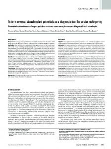
Steady state visual evoked potentials (SSVEP) are a continuous response of the brain to a repetitive stimulation with a certain frequency. Measured from the scalp, SSEP’s have the form of sinusoidal signal which fluctuate with frequency of stimulation [9]. Steady state evoked potentials are divided in three main groups according to the type of stimulation: visual, audio and through skin receptors. The former type of evoked potentials is used from the control purposes in this work, and is therefore presented n more detail below. As it was mentioned the visual evoked potentials are significant voltage fluctuations resulting from visually evoked neural activity. Neurons in the visual cortex response to the flickering stimuli at the frequency of the flickering light. SSVEP is characterized as am in crease in EEG activity at the stimulus frequency [10], [11]. The SSVEP transformed from time domain to the frequency domain by using Fourier method, shows that without fundamental component at stimulus frequency also harmonics are found (see Fig. 1).
Fig. 1. Measured EEG signal (left) and the EEG frequency spectrum (right). When the person is looking at the light source which is blinking with 7 Hz then the power of the fundamental component and first harmonic of this signal will be bigger than others components
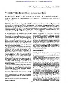
Fig. 2. The measured EEG signal (left) and the power spectrum of EEG signal (right)
The frequency spectrum in Fig. 1, obtained via a Fourier method of the measured signal, shows peaks at the frequencies corresponding to the stimulation frequency and harmonic frequencies. The different frequency spectrum is computed from the FVEP signal. The Fig. 2 shows the FVEP spectrum, which was induced in the visual cortex by OFF-to-On flash of light source. As can be seen from the Fig. 2, the power spectrum of FVEP has low power and there is no component which is clearly higher than other. Therefore, the classification of certain command can not be done by observation of certain component in the power spectrum. The different methods must be used for that purposes. We are proposing artificial neural network, which can be train to classify different FVEP induced by different light codes. In the next chapter, 32
we are presenting the experiments and the results of classification of two types of FVEP which were induced by two different flashing light sources.
scheme of the experiment is shown in the Fig. 6. The trigger signal which describes when the flash starts and ends was recorded with an EEG signal to the computer. In order to know the behaviour of the visual cortex at time of light impulse and after light impulse, the recorded EEG was divided in two sections, i.e., first sections holds EEG values that were recorded at time of flash and second section holds the EEG values which were recorded 500 ms after flash. The mean values of each section were estimated. The results are shown in the figure 3. Three curves represent three channels O1, Oz and O2. The results shows that mean values of each segment of each person are different. The different which is between channels O1, Oz and O2 appeared, because of several reasons, i.e., the impedances between reference electrode and electrodes above visual cortex are not equal, the phases of measured signals are different etc.
Experiments and data The employment of the artificial neural network can be one possibility for classification of user commands. The recognition off the user command can be restricted with the output of neural network. The scheme of the proposed method is shown in the Fig. 4. The experiment was performed in order to get needed data for the artificial neural network training. The screen (monitor) of the computer was used to build two types of stimulators, i.e., the blink of screen and the shifts of chessboard on the screen. The 60 ms flash or shift of screen which appears each second (periodic) or randomly ware used in the experiment. The EEG was measured from electrode positions O1, O2 and Oz according to the international 10-20 system by the use of gold electrode. A reference electrode was mounted on the forehead. Data were amplified with a bipolar EEG-amplifier and recorded with computer. The band-pass 0.5 – 100 Hz filter was used. All measurements were performed with a sampling rate of Fs = 1000 Hz. Two persons (each male from 23 to 30 years old) were recruited for experiments. The persons were asked to look at the screen which was blinking by periodic sequence about the 1 minute. After recording the EEG the person was asked again to look at screen which was blinking by randomly appearing flash about 3 minutes. The same task was repeated with a chess-board visual stimulator. The
Fig. 3. The impulse response of visual cortex of person “A”. Three channels O1, Oz and O2
Fig. 4. The classification with neural network scheme. There are used two types light codes, i.e., one is periodic and other is aperiodic (randomly appearing blink). The artificial neural network should classify two different classes from measured EEG
Fig. 5. The scheme of the experiment. The two types of stimulator were used and two sequences of blinks or shifts
33
commonly used tool for checking randomness of the data set. This randomness is ascertained by computing autocorrelations for data values at varying time lags. If the data set is random, such autocorrelations should be near zero for any and all time lag. The autocorrelation plot of the person “A” starts with autocorrelation 0.44 at lag 1 that gradually decreases to the zero at lag 12. The plot show that is very small associative ability to infer from a current value Yi as to what the next value Yi+1 will be. The autocorrelation plots of the person “B” start at very small autocorrelation 0.037 and gradually decrease to the zero at lag 35. The plots shows that are tiny associative ability to infer from a current value Yi as to what the next value Yi+1 will be. Such small associative is the essence of very big randomness in the given data. Therefore, the input vector for ANN must be chosen (formatted) from such features which describes leastwise some of the visual cortex reaction to OFF-to-On flash.
Fig. 6. The scheme of preparation of input vector for artificial neural network. The EEG signals are transferred from time domain to the frequency domain using Fourier method
It is interesting to know about randomness of an available data set. The autocorrelation plots are a Table 1. Results of classification. The classification was performed to EEG signals, which were evoked during blinks of the monitor screen
Neur. 5
Person “A” Neur. 10
Neur. 15
Neur. 5
Person “B” Neur. 10 Neur. 15
25
Ml= 14,95 % Dl=0,26 Mt= 14,95 % Dt=0,25
Ml= 13,28 % Dl=1,95 Mt=13,26 % Dt=1,88
Ml= 14,14 % Dl=1,47 Mt=14,19 % Dt=1,30
Ml= 20,95 % Dl=3,32 Mt=21,13 % Dt=2,94
Ml= 19,84 % Dl=1,33 Mt=19,91 % Dt=1,14
Ml= 19,28 % Dl=2,73 Mt=19,26 % Dt=2,63
50
Ml= 7,67 % Dl=1,16 Mt=7,76 % Dt=1,61
Ml= 4,05 % Dl=7,07 Mt=4,12 % Dt=7,47
Ml= 5,14 % Dl=10,81 Mt=5,25 % Dt=11,07
Ml= 4,38 % Dl=0,27 Mt=4,40 % Dt=0,25
Ml= 4,11 % Dl=0,25 Mt=4,14 % Dt=0,28
Ml= 2,74 % Dl=0,43 Mt=2,81 % Dt=0,56
75
Ml= 2,85 % Dl=3,44 Mt=2,92 % Dt=3,54
Ml= 0,64 % Dl=1,58 Mt=0,66 % Dt=1,54
Ml= 0,04 % Dl=0,00 Mt=0,04 % Dt=0,00
Ml= 2,84 % Dl=0,62 Mt=2,93 % Dt=0,57
Ml= 1,08 % Dl=0,85 Mt=1,12 % Dt=0,74
Ml= 0,26 % Dl=0,15 Mt=0,29 % Dt=0,16
100
Ml= 2,39 % Dl=7,00 Mt=2,44 % Dt=7,09
Ml= 0,27 % Dl=0,37 Mt=0,30 % Dt=0,39
Ml= 0,00 % Dl=0,00 Mt=0,01 % Dt=0,00
Ml= 0,45 % Dl=0,17 Mt=0,50 % Dt=0,16
Ml= 0,01 % Dl=0,00 Mt=0,04 % Dt=0,00
Ml= 0,02 % Dl=0,00 Mt=0,03 % Dt=0,00
Table 2. Results of classification. The classification was performed to EEG signals, which were evoked during chess board shifts on the monitor screen
Neur. 5
Person “A” Neur. 10 Neur. 15
Neur. 5
Person “B” Neur. 10 Neur. 15
25
Ml= 24,71 % Dl=5,26 Mt=24,76 % Dt=5,29
Ml= 22,83 % Dl=0,58 Mt=22,94 % Dt=0,86
Ml= 22,66 % Dl=6,27 Mt=22,70 % Dt=5,62
Ml= 18,43 % Dl=2,98 Mt=18,59 % Dt=2,77
Ml= 16,67 % Dl=0,31 Mt=16,71 % Dt=0,34
Ml= 16,85 % Dl=1,31 Mt=17,02 % Dt=1,16
50
Ml= 16,22 % Dl=2,39 Mt=16,47 % Dt=2,13
Ml= 12,29 % Dl=2,66 Mt=12,38 % Dt=3,19
Ml= 10,38 % Dl=7,22 Mt=10,49 % Dt=7,66
Ml= 0,62 % Dl=0,06 Mt=0,66 % Dt=0,05
Ml= 0,22 % Dl=0,03 Mt=0,24 % Dt=0,03
Ml= 0,09 % Dl=0,04 Mt=0,12 % Dt=0,06
75
Ml= 13,16 % Dl=30,59 Mt=13,39 % Dt=33,56
Ml= 7,35 % Dl=10,79 Mt=7,40 % Dt=11,16
Ml= 4,23 % Dl=6,96 Mt=4,29 % Dt=7,03
Ml= 0,05 % Dl=0,00 Mt=0,07 % Dt=0,00
Ml= 0,02 % Dl=0,00 Mt=0,03 % Dt=0,00
Ml= 0,03 % Dl=0,00 Mt=0,03 % Dt=0,00
100
Ml= 11,91 % Dl=29,94 Mt=12,06 % Dt=29,96
Ml= 4,61 % Dl=10,55 Mt=4,67 % Dt=10,48
Ml= 6,69 % Dl=12,19 Mt=6,80 % Dt=12,04
Ml= 0,30 % Dl=0,00 Mt=0,02 % Dt=0,00
Ml= 0,00 % Dl=0,00 Mt=0,00 % Dt=0,00
Ml= 0,00 % Dl=0,00 Mt=0,00 % Dt=0,00
34
We propose an idea to use components of the power spectrum as features of the measured signal in this work. Since, brain-computer interface should work in the real time all measured EEG signals were divided segments of the 1 second length, i.e., the classifier must recognize the user command every second. The power spectrum is computed from these segments of every channel (O1, Oz and O2) using Fourier method in the next step and the mean power spectrum from all three spectrums is estimated. The preparation of data is shown in the Fig. 7. In this work three artificial neural networks were used, i.e., with 5, 10 and 15 in the input layer. The neural network was trained to classify signals according the input vector of the features which length was: [P1 P2 … PN]T, where N = [25, 50, 75 and 100]. The components of power spectrum for the input vector were chosen from 1 to N. The neural network must classify the measured signals from these input vectors when person was looking to periodic or randomly blinking stimuli. All data set was divided in to three parts, i.e., 60% training data, 20% validation data and the last 20% is used as test data. The testing, validation and training data were formatted in the random sequence. The cross validation was used for the stopping the artificial neural network training. The classification results are presented in the next chapter.
Conclusions 1. The results shows, that the classification of EEG signals, which are recorded when person was stimulated with two different stimuli, can be performed by using the artificial neural networks. This conclusion confirms an assumption, that the certain light code can be used for the brain-computer interface. The person’s reacts differently to the two types of stimuli, i.e., light flash or the shifts of chess board. According the results person “A” is more sensitive for the stimulation with light flash, but person “B” is more sensitive to chess board shifts. Therefore, the type of stimuli should depend on the user. 2. The optimal number of features and the amount of neurons in the input layer depends on the user, i.e., on the sensitivity to the certain stimuli. The artificial neural network must be designed individually for every user. Future works will involve the investigation how the different time of day impacts the classification results. References 1. Thomas C. Ferree, Phan L. Luu, Gerald S. Russell, Don M. Tucker. Scalp electrode impedance, infection risk and EEG data quality. – 2001. – P. 536–544. 2. Kennedy P. R., Bakay R. A. E., Moore M. M., Adams K., Goldwaithe J. Direct Control of a Computer from the Human Central Nervous System // IEEE Transactions on rehabilitation engineering. – June 2000. –Vol. 8, No. 2. – P. 198–202. 3. Saastamoinen A., Pietilä T., Värri A., Lehtokangas M., and Saarinen J. Waveform detection with RBF network application to automated EEG analysis // Neurocomputing. – 1998. – No. 20. – P. 1–13. 4. Birbaumer N., Ghanayim N., Hinterberger T., Iversen I., Kotchoubey B., K¨ubler A., Perelmouter J., Taub E., and Flor H. A spelling device for the paralysed // Nature. – 1999. – No. 398. – P. 297–298. 5. Hinterberger T., Kaiser J., Kbler A., Neumann N., and Birbaumer N. The Thought Translation Device and its Applications to the Completely Paralyzed // In Diebner, Druckrey, and Weibel, editors, Sciences of the Interfaces. Genista-Verlag, T¨ubingen. – 2001. – P. 232–240. 6. McFarland D. J., Sarnacki W. A., Schalk G., and Wolpaw J. R. EEG-based brain-computer interface: Real-time adaptation of feature weights // Soc. for Neurosci., submitted for publication. – 1991. – Vol. 78. – P. 252–259. 7. Lee P.-L., Wu C.-H., Hsieh J.-C., Wu Y.-T. Visual evoked potential actuated brain computer interface: a brain-actuated cursor system // Electronics letters. – 2005. – Vol. 41, No. 15. – P. 832–834. 8. Bas¸ar-Eroglu C., Strüber D., Schürmann M., Stadler M., Gamma-band responses in the brain: a short review of psychophysiological correlates and functional significance // Int. J. Psychophysiol. – No. 24. – P. 101–112. 9. Regan D. Human brain electrophysiology: Evoked potentials and evoked magnetic fields in science and medicine. – New York: Elsevier Pubs, 1989. – P. 1–50. 10. Regan D. Human Brain Electrophysiology. – New York: Elsevier, 1989. – P. 100–110. 11. Bodis-Woliner I., Ghilardi M. F., and Mylin L. H. The importance of stimulus selection in VEP practice: the clinical relevance of visual physiology. – R. Q. Cracco and I. BodisWoliner (Eds.), Evoked Potentials. – Alan R. Liss, New York, 1986. – P. 15–27. Submitted for publication 2007 11 05
Results The classification results of EEG signals, which were recorded when persons were looking at the flashing screen is presented in the Table 1. The results are sorted by a number of the features and by the number of used neuron in the input layer. The features are in the first left column and the amount of neurons is shown in the first line in the table. The shortenings are used in the Tables 1 and 2: Ml – the mean value of faulty classified training data [%], and Dl is dispersion of faulty classified training data. Mt – the mean value of faulty classified testing data [%], and Dt is dispersion of faulty classified testing data. According Table 1 the neural network classifies the EEG signals without error when the number of used features is N = 100 and the number of neurons in the input layer is equal to 15. The highest number of faulty classified data, as was expected, is received when the classification was performed with 5 neuron network and N = 25 features. The classification results of EEG signals, which were recorded when persons were looking at the shifting chess board on the screen is presented in the Table 2. The results are sorted by a number of the features and by the number of used neuron in the input layer. The features are in the first left column and the amount of neurons is shown in the first line in the table. According Table 2 the neural network classifies the EEG signals only of person “B” without error when the number of used features is N = 100 and the number of neurons in the input layer is equal to 15. Meanwhile, the classification of person “A” EEG signals can be performed with errors about 6%. The highest number of faulty classified data, as was expected, is received when the classification was performed with 5 neuron network and N = 25 features.
35
V. Raudonis, G. Narvydas, R. Simutis. A Classification of Flash Evoked Potentials based on Artificial Neural Network // Electronics and Electrical Engineering. – Kaunas: Technologija, 2008. – No. 1(81). – P. 31–36. This paper presents how the certain sequences of the light impulses (or narrows squares) can be used to increase the number of commands for a brain-computer interface which is based on visually evoked potentials. The observation of the certain components in the power spectrum of the measured EEG will not give needed results, because the blink of the stimulators is not periodic. Therefore, different methods must be used to recognize a user commands. In this paper, a classification of flash visual evoked potentials (FVEP) of visual cortex which is induced by OFF-to-ON flash of light source based on artificial neural network is presented. The presented below results shows that is possible two classify EEG signals, which were recorded when person was visually stimulated with two type’s stimuli. Ill. 6, bibl. 11 (in Lithuanian; summaries in English, Russian, Lithuanian). В. Раудонис, Г. Нарвидас, Р. Симутис. Классификация возбужденных бликом света электрических потенциaлов искусственной нейронной сетью // Электроника и электротехника. – Каунас: Технология, 2008. – № 1(81). – C. 31–36. Увеличение числа команд для системы человеческий мозг – компьютер ограничивает гармоники в EEG сигнале, которые появляются, когда визуально стимулируется человек с помощью периодично мигающего света. Для увеличения числа команд мы предлагаем использовать импульсы света, появляющиеся в определённом порядке. Импульсы света возбуждаются в области мозга, которая отвечает за обработку изобразительной информации колебаний электрических потенциалов. В спектре такого EEG сигнала нет ярко выраженных компонентов. Мы предлагаем искусственную нейронную сеть для классификации EEG сигналов возбуждённых различными „световыми кодами“. Результаты показали, что классификатор удачно классифицирует сигналы и „световые коды“ и может использоваться для систем человеческий мозг – компьютер. Ил. 6, библ. 11 (на литовском языке; рефераты на английском, русском и литовском яз.).
V. Raudonis, G. Narvydas, R. Simutis. Blyksnio sužadintų potencialų klasifikavimas naudojant dirbtinį neuronų tinklą // Elektronika ir elektrotechnika. – Kaunas: Technologija, 2008. – Nr. 1(81). – P. 31–36. Didinti sąsajos žmogaus smegenys – kompiuteris komandų skaičių kliudo EEG signalo harmonikos, kurios atsiranda stimuliuojant sistemos vartotoją pastoviu dažniu mirksinčia šviesa. Šiame darbe vartotojo komandoms generuoti siūloma naudoti skirtingas šviesos impulsų sekas (šviesos kodus), kurios sužadina taip vadinamus vizualiai sužadintus potencialų skirtumus (FVEP) smegenų srityje, atsakingoje už vaizdo apdorojimą. Šviesos impulsų sužadintame EEG signalo dažnių spektre nėra aiškių vyraujančių dažninių komponenčių ir harmonikų. Todėl šiame darbe neuroninis klasifikatorius yra sukurtas taip, kad klasifikuotų pagal tam tikrą dažninių komponenčių aibę. Tyrimai parodė, kad, naudojant dirbtinį neuroninį tinklą, galima sėkmingai klasifikuoti vartotojo komandas, kurios buvo sugeneruotos naudojant skirtingus „šviesos kodus“. Il. 6, bibl. 11 (lietuvių kalba; santraukos anglų, rusų ir lietuvių k.).
36