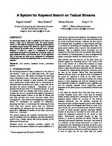
Node 3 enables one of the two FIRs by either asserting or de-asserting vr1325, depending the value of flag (vr78). Node 10 is activated by the done signal from.
16th International Conference on Field Programmable Logic and Applications (FPL 2006), Madrid, Spain.
A COMPILER INTERMEDIATE REPRESENTATION FOR RECONFIGURABLE FABRICS Zhi Guo
Walid Najjar
Department of Electrical Engineering Department of Computer Science & Engineering University of California, Riverside {zguo, najjar}@cs.ucr.edu
ABSTRACT An intermediate representation (IR) is a central structure around which tools such as compilers and synthesis tools are built. In this paper we propose such an IR specifically designed for reconfigurable fabrics: CIRRF (Compiler Intermediate Representation for Reconfigurable Fabrics). We describe an initial implementation of CIRRF as part of the ROCCC compiler for translating C code to VHDL. A case study shows that our IR set is a solid foundation to generate high-performance hardware. 1. INTRODUCTION Several projects have looked at the translation of traditional programming languages, such as C/C++ or Java, to HDLs for mapping onto FPGAs or other similar fabrics. This is a challenging task. The FPGA is an amorphous mass of logic onto which the compiler must create a data-path and schedule the computation. Such a task requires the harnessing of technologies developed for parallelizing compilers as well as those developed for high-level synthesis. At the heart of each compiler or synthesis tool is an intermediate representation (IR) around which the tool is built. In this paper we propose CIRRF (Compiler Intermediate Representation for Reconfigurable Fabrics), an IR designed for the compilation of traditional imperative, high-level languages, targeting reconfigurable devices. CIRRF is intended to be an open standard halfway-point representation between a high-level language and a specific reconfigurable platform. A front tool would translate C/C++, FORTRAN, or Java to CIRRF. Back tools would map CIRRF to a specific target. Loop and array transformations are dealt with in the front tools; target-specific optimizations are implemented in the back tools. CIRRF is designed to be both language and target independent. It differs from traditional compiler IRs in that it supports concurrency, both explicitly and implicitly, as well as the instantiation of and accesses to on-chip storage structures. It records information about loop types, memory interfacing, instruction predication and pipelining. Special instructions for efficient data-path generation are introduced. In this paper we describe an initial implementation of CIRRF as part of the ROCCC compiler for translating C to VHDL. The rest of this paper is organized as follows: Section two reviews related work; Section three presents
CIRRF’s architecture; Section four discusses a case; and section five concludes the paper. 2. RELATED WORK The Streams-C [1] has three distinguished objects processes, streams and signals - in the user-input abstraction. Abstract Syntax Tree (AST) is used to partition a process into the data-path, encompassing basic blocks and pipeline blocks, and control flow. A state machine is generated for the control flow in the AST. User-defined input or output streams form the interfaces with memories. Trident [2] uses LLVM (Low Level Virtual Machine [3]) as a C/C++ front-end to produce low-level object code. The low-level object code is transformed into a predicated IR. SA-C [4]’s input is a single-assignment high-level synthesizable language. The SA-C compiler translates loops into a data-dependence and control-flow (DDCF) graph. A DDCF graph is flattened into a token-driven dataflow graph. The DFG is eventually translated into an abstract hardware architecture graph, which includes timing information. Pegasus [5] is the IR of the CASH compiler. Pegasus decomposes a Control Flow Graph (CFG) into hyperblocks, and hyperblocks are connected by merge and other specialized nodes. 3. CIRRF ARCHITECTURE CIRRF is the IR set of our high-level synthesis compiler, the ROCCC (Riverside Optimizing Compiler for Configurable Computing) compiler. ROCCC is built using SUIF2 [7] and Machine-SUIF [8]. CIRRF consists of two distinct but equivalent representations [Figure 1]. The HiCIRRF format is essentially C code augmented with macros while the Lo-CIRRF format is semantically similar to assembly code. The advantage of this approach, which is commonly used in various compiler IRs, is that it allows the user to have multiple levels of entry into the IR.
Hi-CIRRF
Lo-CIRRF
= C + macros
low level statements user directives
Figure 1 – CIRRF overview
16th International Conference on Field Programmable Logic and Applications (FPL 2006), Madrid, Spain.
Debugging, for example, would a lot easier at the HiCIRRF level. A functional-cycle-accurate simulation of the generated code would be feasible at the Lo-CIRRF level. The macros in Hi-CIRRF are used to: • Instantiate and access buffers. • Indicate pipelining and clock-cycle level hardware timing constrains. For example: imply back-end to instantiate registers to eliminate recurrence; enforce a pipeline delay for IP wrapper generation. • Invoke hardware bitwise and arithmetic operations, such as bit-insert, bit-extract, and minimum of two values. • Invoke hardware look-up tables and IP cores. In Lo-CIRRF the code is similar to assembly code. It consists of a data and control flow graph with the following characteristics: • Virtual statically single assigned registers. • Register name indicates type (signed, unsigned) and bit size. • Predicators of predication-guarded instructions and pipelining information of controller-controlled instructions. 3.1. Hi-CIRRF The ROCCC system performs conventional loop transformations. It also carries out the following hardwarespecific analysis and transformations. Scalar replacement. The front-end decouples a do-all loop’s array accesses from computation. Figure 2 (a) shows the original C code of a gray scale transformation example. After undergoing scalar replacement, the computation is isolated from memory accesses [Figure 2 (b)] by a smart buffer. The smart buffer will be synthesized on configurable fabrics as the interface with memory. One important characteristic of smart buffers is that they reuse input data between iterations and push one iteration’s input data initiatively to the data-path, rather than being accessed by the data-path [9]. For a 3x3 window sliding over a twodimensional array, without the smart buffer, each pixel needs to be read nine times from memory, while a smart buffer reduces the memory access to three times. A smart buffer of an unrolled loop can save more memory access. The syntax of a two-dimensional smart buffer macro is: smartbuffer2(input_array_name,address_index_1, address_index_2, scalar_1, offset_1_1, offset_1_2, scalar_2, offset_2_1, offset_2_2, ……); For example, in the smart buffer macro in Figure 2 (b), the last three parameters (x4, 1, 1) stands for: x4 = a[i+1][j+1]; The syntax of FIFO buffers is similar. Currently we have the following constraints on buffer macros. An array can only appear in at most one buffer macro. The address indexes of buffers are also the loop counters. The operator between an address index variable and the offset can only be either addition of subtraction.
Figure 2 – A gray scale transformation example in C Feedback variable detection. The compiler detects scalar recurrence between adjacent iterations. For example, for a loop having a statement “sum = sum + a[i]”, to eliminate the loop-carried dependency, the compiler replaces the sum on the left and the sum on the right with store2next() macro and load_previous() macro, respectively. These macros guide the back-end to instantiate a feedback register to store the current sum for the next iteration, and consequently transform the loop to a do-all-loop. The output from the front-end is in the forms of both an IR file and an intermediate C with macros. Users could do further optimizations and add pragmas onto the intermediate C. 3.2. Lo-CIRRF Starting from a conventional CFG, the compiler finds loops and loop-depth. Loop types are recorded in the IR by recovering them from user-added pragmas: Currently, these include one-dimensional do-all loop, two-dimensional perfect nested do-all loop, and non-do-all loop. The preprocess phase of the back-end converts macros in HiCIRRF into corresponding instructions. Particularly, buffer macros are converted into buffer instructions and put into separated nodes. We categorize basic nodes into two types: do-all nodes and non-do-all nodes. Lo-CIRRF records different dataflow and scheduling information accordingly. 3.2.1. Building Lo-CIRRF for do-all nodes For a do-all loop, Lo-CIRRF provides field to exploit both instruction-level and loop-level parallelisms. The compiler performs if-converse in a way that any node has at most two predecessors. In order to allow the data-path to execute multiple loops simultaneously, the IR has a “execution level” field for each instruction inside a do-all node so that each level is an instantiation of one iteration. Statically single assigned
16th International Conference on Field Programmable Logic and Applications (FPL 2006), Madrid, Spain.
flag = 1; for (m = 0; m < 10; m = m + 1) { if(flag == 1) { for(i = 1; i < 251; i = i + 1) b[i]=(3*a[i-1]+5*a[i])+(7*a[i+1]+9*a[i+2])+11*a[i+3]; } else { for(j = 1; j < 251; j = j + 1) d[j]=(3*c[j-1]+5*c[j])+(7*c[j+1]+9*c[j+2])+11*c[j+3]; } flag = flag ^ 1; } return; } The first highlighted segment is a 5-tap FIR reading array a and writing array b, while the second highlighted segment is a 5-tap FIR reading array c and writing array d. flag switches the execution of these two segments alternatively. The two inner loops are do-all loops, while the outer loop (the one with loop counter m) is not.
Figure 3 – An alternative FIR example in C variables are added by the compiler to duplicate a variable if that variable’s definition reaches more than one level of execution lower. Thereby, any variable’s definition is always one execution level higher. Multiplexers are added, and speculators are duplicated and propagated along with execution levels. Notice that each execution level represents a single iteration at a given execution phase. Lo-CIRRF provides another field, “pipeline stage” to record pipelining information. The instructions belonging to the same execution level are either all latched or all nonlatched. Multiple consecutive execution levels may be assigned into the same pipeline stage. Having both execution level and pipeline stage separates data-flow building and pipelining, and provides compiler designers the opportunity to implement different pipelining strategies. The compiler generates the smart buffers and output FIFOs in VHDL at compile time [9], as well as the datapaths [6].
PFW $vr2.u1, $vr1.u1 vr1 and vr2 are two predicators. The instructions guarded by vr2 are one pipeline stage later than the ones guarded by vr1. Their types are u1, which stands for unsigned one-bit. The branch instructions of basic nodes are replaced by Boolean instructions, whose destination operands are evaluated by this basic node’s successor nodes. Essentially, Lo-CIRRF describes a DFG, in which doall loop nodes are connected together by non-do-all nodes. Then the compiler’s VHDL generator emits VHDL code for the entire DFG, including buffers, at compile time. 4. CASE STUDY In this case study, besides reporting the synthesis results of the gray scale transformation example discussed in previous sections, we examine CIRRF on another application, an alternative finite impulse response filter
3.2.2. Building Lo-CIRRF for non-do-all nodes A non-do-all basic node either belongs to a non-do-all loop or does not belong to any loop at all. Multiple instructions might belong to the same execution level and can be executed simultaneously to exploit instruction level parallelism. Notice that for a non-do-all basic node, at most one iteration is executed at a time. Lo-CIRRF has a predication field for each instruction to schedule the execution of non-do-all nodes. Each pipeline stage is guarded by a predicator. The format is: ADD $vr4, $vr3, $vr2, $vr1 vr4 is the destination operand and vr3 and vr2 are the source operands. vr1 is the predicator, which is also a source operand. Predicators are passed inside basic nodes for scheduling purpose. A special instruction, PFW (predicator forward), is used to pass a predicator from the current stage to the next stage, which may be or may not be in the same node:
Figure 4 – The DFG and IR of alternative FIR
16th International Conference on Field Programmable Logic and Applications (FPL 2006), Madrid, Spain.
Table 1 - Synthesis results of case study examples DP-size mem bus # of clock iter. per (bit) bit-size slices (MHz) cycle gray scale tran. 16 16 318 59.7 0.5 altern. FIR 8 8 531 100 1 (FIR). Figure 3 shows the original C code. The two do-all inner loops (the two highlighted regions) are executed alternately. Each of these two inner loops is a 5-tap FIR. Each FIR’s loop body is aggressively pipelined, and the resulting data-path has a throughput of one iteration per clock cycle [Figure 4 (a)]. All the non-do-all nodes are predicated. We list the instructions of these nodes in Figure 4 (b). Node 2 and node 10 are the head and tail nodes of the outer loop, respectively. The first instruction of node 2, the ior instructions, produces the predicator (vr1321) for the two instructions below it (pfw and sle) by examining a valid output predicator from either node 1 (not shown), the first active node; or node 11, the loop tail. Figure 4 (c) depicts node 2’s circuit in detail. Guarded by vr1321, the sle instruction asserts its destination operand when the outer loop is done, or de-asserts its destination operand when needing to execute a new outer loop iteration. Node 2’s pfw instruction forwards a valid vr1321 to the two successor nodes, node 3 and node 11, for their predicator evaluation. Node 3 enables one of the two FIRs by either asserting or de-asserting vr1325, depending the value of flag (vr78). Node 10 is activated by the done signal from one of the FIRs’ loop controller and updates the value of flag (vr230) and the loop counter m (vr233). Node 11 indicates the completion of the whole procedure. Table 1 shows the synthesis results of the gray scale transformation example discussed in previous sections and the alternative FIR. The targeting FPGA is Xilinx xc2v8000-5 with 46592 slices in total. The generated VHDL are synthesized and placed-and-routed using Xilinx ISE 6.2.03i. The second and the third columns are the datapath’s bit-size and BRAM bus’s bit-size. # of slices and clock rate are collected from place-and-route reports. The last column is the number of do-all loop iterations executed per clock cycle. For gray scale transformation, the resulting data flow is capable of executing one iteration every clock cycle. Notice we configure the BlockRAM’s data bus (the third column) to have the same bit-size as that of the data elements (pixels), and every iteration needs four (2x2) pixels. Though the smart buffer reuses one column of the pixels loaded in the previous iteration, it still needs two cycles to load the remaining two new pixels. This explains the reason that for the gray scale transformation example, the number of iterations per cycle is 0.5. For the alternative FIR, when either one of the two do-all loops is active, the corresponding smart buffer exports one window of data (five elements) to the data-path every clock cycle, and therefore the circuit executes one iteration per cycle. #
of slices consists of the hardware of two do-all loops (including the data-path and controller for each FIR) and the hardware of the non-do-all nodes, as shown in Figure 4 (a). 5. CONCLUSION We have presented CIRRF, an intermediate representation for compiling high-level languages to reconfigurable fabrics. CIRRF has two parts, Hi-CIRRF and Lo-CIRRF. Hi-CIRRF is essentially C with macros. The macros are used to record information associated with buffers, pipelining, look-up tables, special operations etc. LoCIRRF decomposes conventional CFGs into do-all loop nodes and non-do-all nodes. The loop body instructions of a do-all loop are placed into execution levels. Each execution level is an instantiation of one iteration at different execution phases. Lo-CIRRF provides a platform for the compiler to aggressively pipeline do-all loops. Nondo-all nodes are predicated in Lo-CIRRF and predicators are passed within and between nodes. We have shown, through case studies, how CIRRF models the application examples and provides a solid foundation for the compiler to generate efficient hardware. 6. REFERENCES [1]
M. B. Gokhale, J. M. Stone, J. Arnold, and M. Lalinowski. Stream-oriented FPGA computing in the Streams-C high level language. In IEEE Symp. on FPGAs for Custom Computing Machines (FCCM), 2000.
[2]
J. Tripp, K. Peterson, C. Ahrens, J. Poznanovic, M. Gokhale. Trident: An FPGA Compiler Framework for Floating-Point Algorithms, int. Conference on Field Programmable Logic and Applications (FPL 2005). Finland, 2005
[3]
The LLVM Compiler Infrastructure. http://llvm.org/ 2006
[4]
W. Najjar, W. Böhm, B. Draper, J. Hammes, R. Rinker, R. Beveridge, M. Chawathe and C. Ross. From Algorithms to Hardware - A High-Level Language Abstraction for Reconfigurable Computing. IEEE Computer, August 2003.
[5]
M. Budiu and S. C. Goldstein. Pegasus: An efficient intermediate representation. Technical Report CMU-CS-02107, CMU, May 2002.
[6]
Z. Guo, B. Buyukkurt, W. Najjar and K. Vissers. Optimized Generation of Data-path from C Codes for FPGAs, Int. ACM/IEEE Design, Automation and Test in Europe Conference (DATE 2005). Munich, Germany, March, 2005.
[7]
SUIF Compiler System. http://suif.stanford.edu, 2006
[8]
Machine-SUIF. 2006 http://www.eecs.harvard.edu/hube/research/machsuif.html
[9]
Z. Guo, B. Buyukkurt, W. Najjar. Input Data Reuse In Compiling Window Operations Onto Reconfigurable Hardware, Proc. ACM Symp. On Languages, Compilers and Tools for Embedded Systems (LCTES), Washington, DC, June 2004.