www.ccsenet.org/nct
Network and Communication Technologies
Vol. 1, No. 1; June 2012
A Complete Interoperable eHealth System Based on ZigBee Pro Standard Iker Caballero1, Javier Vicente1, Begoña García1 & Amaia Méndez1 1
DeustoTech-Life Unit, Deusto, Institute of Technology, University of Deusto, Bilbao, Spain
Correspondence: Amaia Méndez, DeustoTech-Life Unit, Deusto, Institute of Technology, University of Deusto, Avda. de las Universidades, Bilbao, Spain. Tel: 34-944-139-000. E-mail:
[email protected] Received: November 14, 2011 Accepted: November 30, 2011 Online Published: June 1, 2012 doi:10.5539/nct.v1n1p79
URL: http://dx.doi.org/10.5539/nct.v1n1p79
This work was partially supported by the Basque Country Department of Education, Universities and Research Abstract The eLife research group at University of Deusto is trying to socialize new technologies through projects focused on health. Telemedicine and eHealth systems are being used widely to improve health services or to develop value added ones. The main aim of this project is to design an eHealth system that increases life quality. It is focused on people who need daily support because of age, disability or disease. A wireless sensor network has been developed and it is integrated in a Set-Top-Box that allows controlling the network from TV. Besides, some devices have been designed so the article describes them as well as the software development. Keywords: ZigBee Pro, eHealth, electronic design, wireless sensor network 1. Introduction Biomedical Engineering and Information and Communication Technologies are growing together at high speed. The European Commission has been promoting them for two decades through its Framework Programmes (FP), which are focused on multiple topics. One of most important areas where both participate is telemedicine, better known nowadays as telehealth. In the FP6 (2002-2006) health research projects were priorities in many cases (Iakovidis, Le Dour, & Karp, 2007). More specifically, personal eHealth systems and rehabilitation technologies can be found among the Information Society Technologies priorities, neurosciences and medical imaging in Life Sciences, Genomics, and Biotechnology for Health Programme, and biosensors as part of the Nanotechnologies Programme. The FP7 is organized into five different blocks encompassing both collaborative and individual group research (in the latter case, without need for internationalization). It also supports researcher mobility and career development. The Collaboration block, comprising two thirds of the total budget, is also divided into different topics. One of them is called Health and there are also topics related to nanotechnologies and ICTs, as in FP6. Telemedicine (Krol, 1997) defined as the use of computer and communication technologies to provide healthcare services between distant locations, started by the sharing of information between medical centers. The first applications were focused on audio and video links between these locations in order to resolve problems all together if necessary, to establish remote consultations and to access common databases. Nowadays, with the rapid growth of technologies, a wide range of health services have been developed with the support of sizeable research programs. Common applications are based on image and signal processing, specialized medical systems or telecommunication standards, among others. There is also great support for wearable systems (Lymberis & Dittmar, 2007; Chiu, 2006) and applications in order to complement eHealth and monitoring systems (McAdams, 2011). Nevertheless, these eHealth advances have not been introduced into the market nor adopted by it. There are a lot of technological, legal or financial barriers (Paul, Pearlson, & McDaniel, 2009; Gibbons, 2008) involved in this process, sometimes too difficult to resolve. In technological terms, we can encounter problems not only in the user needs (if technology can solve the particular problem) but also in the user capabilities (if end-user can manage new technologies and applications). It is important because the users’ capabilities vary, and rural people are, on average, the least technologically proficient but the neediest of such services (Sudhahar, y otros, 2010). Technological barriers are cited as a significant cause of the low utilization rates of eHealth services, but a
Published by Canadian Center of Science and Education
79
www.ccsenet.org/nct
Network and Communication Technologies
Vol. 1, No. 1; June 2012
reduction of these barriers does not guarantee wider utilization since other barriers are as important as the technological ones. There is also a disagrement over costs (Wells, 2002; Poon & Zhang, 2008): whether eHealth systems cause a cost reduction or not (Nitzkin, 1996), and who such reduction would be for. We should realize that the population is aging (Mauksch, 1987), thus increasing the utilization rates of health services (Moullec & Ray, 2009). The elderly is a collective that generates higher costs than the rest of the population. This idea, together with the ever increasing population, shows that health care costs are also increasing. The development of new prevention-oriented services can be translated into medium to long term investments (Iluyemi & Briggs, 2009; Hui, Yanting, & Xue, 2010). However, the inclusion of technology in the health sector implies a need for training (for both specialists and patients) due to possible deficiencies in technological knowledge. This failing results in the development of adaptive user interfaces (Vasilyeva, Pechenizkiy, & Puuronen, 2005). Health services have to ensure not only accurate and up-to-date, but also easy to understand, information. These interfaces should take into account both content and navigation adaption. The contents should be adapted to the patients’ situation, illness and treatment. Users could choose how to see the content, but it is the system that offers possibilities based on the specific patient. Another important feature of eHealth services is the information shared through electronic medical records (Detmer, Bloomrosen, Raymond, & Tang, 2008; De, 2005). As you can see, many factors contribute to the economic effects of eHealth systems, and thousands of hours could be spent discussing them. All these changes should be well organized with the aim of avoiding waste and inefficiency, so a better management must be achieved (Sheng, Hu, Wei, & Ma, 1999). A well organized service reduces the number of treatment days (Akematsu & Tsuji, 2009). If there are affordable systems for patients, the diagnostics and some tests could be performed at a patient’s home without the need for new appointments using telematic services. Apart from multimedia (Cabral & Kim, 1996) and telematic services, wireless sensor networks (Yan, Huo, Xu, & Gidlund, 2010) have a place in the end users’ home. These networks provide the link between the user and the service itself. If mass adoption of eHealth systems is desired, not only is user adaption to the application needed, but also the standardization of systems with the aim of different services and devices operating together, in other words, promoting interoperability. Bear in mind that often standardization, and therefore interoperability, is contrary to the interests of manufacturers, but it encourages competitiveness. And this competitiveness means that prices fall. Also important is the collaboration of government agencies such as the European Telecommunications Standards Institute (ETSI) (Hine, Petersen, Pluke, & Sund, 2008), as well as partnerships and alliances between companies (Piniewski, Muskens, Estevez, Carroll, & Cnossen, 2010). On one hand, the ETSI proposes the standardization of both application framework and architecture. On the other hand, Continua Alliance has designed some guidelines for the standardization of health devices. There are also social features which are truly important, such as security. Health information is very sensitive and technology should be capable of maintaining its privacy. So, both technical and social factors must be analyzed for a strong standardization (Chadwick, 2007). Although there are a lot of factors involved in the development of telehealth services, the main aim of this project is to try to promote standard-based systems in order to achieve interoperable applications for eHealth. This aim could increase the number of interoperable devices and thus competitiveness. Therefore, the prices of end users’ systems will be reduced. In accordance with this aim, several specific goals can be highlighted:
Design of a standard-based system to permit interoperability between devices and to reduce the final costs. Use of a single technology for healthcare devices and home automation.
Design a gateway device in order to control the system from a PC user application.
2. Methods
It is not new that each wireless and wired technology has its own advantages and disadvantages. However, mobility is one of most important features in eHealth systems or other kinds of patient monitoring systems and it can only be provided by wireless technologies. Therefore, wireless technologies have gained much ground in the eHealth market. Another important feature is low power consumption, so the technology selected should be wireless and with reduced power consumption (Chien, Xu, & Molloy, 2010). Bluetooth (in its low-energy version), ZigBee and ANT are technologies with these features. Each one has its advantages and disadvantages, in terms of number of nodes, topologies supported, etc. But it is difficult to point out one of them as the best or the favorite. There are a lot of reviews comparing them (Gomez & Paradells, 2010), but it is quite clear that each one has its own market.
80
ISSN 1927-064X
E-ISSN 1927-0658
www.ccsenet.org/nct
Network and Communication Technologies
Vol. 1, No. 1; June 2012
Continua Alliance, mentioned above, has selected Bluetooth-LE and ZigBee for its second version of guidelines (Piniewski, Muskens, Estevez, Carroll, & Cnossen, 2010). Bluetooth stands as the technology for mobile devices (e.g., a watch with an ECG monitor connected to the mobile phone), while ZigBee focuses toward low-power sensors (bed pressure sensors, fall detectors, etc). The problem facing this choice is the need for platforms that support different technologies, thus adding complexity to the system. It is not a complexity in development, but for interoperability. It is difficult to achieve interoperability using a single technology, so adding different technologies makes it more difficult. In addition, it involves the development of gateways (Hwang, In, Park, & Eom, 2003; Song, Zhou, Zhang, & Song, 2008). These gateways are common elements used to interconnect different systems or technologies in order to provide a more complete service. Thus, indoor sensor networks can be connected to telematic systems to send or record information (Farshchi, Pesterev, Nuyujukian, Mody, Judy, & Bi-Fi, 2007), and also to control or manage the network from remote sites. However, the inclusion of different technologies in the indoor system involves the development of gateways within the sensor network itself. For this reason, the project develops a platform based on a single technology. The technology selected for this project was ZigBee, which provides the best performance for a single technology based system and it is based on IEEE802.15.4 standard (Bandyopadhyay, 2010). ZigBee adds network and routing services to IEEE802.15.4. ZigBee was created by the ZigBee Alliance, a non-profit association whose main aim is to develop standards suiting the real evolving needs of manufacturers and developers. The Alliance designed some application profiles with industrial experts to meet the market needs. Specifically, the Home Automation Profile offers a global standard for smart homes, enabling the control of lights, environment or security among others. There is also a Health Care Profile, which enables reliable monitoring of non-critical healthcare services, targeted as independent life, health or wellness. Nowadays the focus is the end user, that is the customer, and they are demanding standard systems that can operate together, in order not to fill the house with numerous independent systems. 2.1 ZigBee Basics and Wireless Devices ZigBee is a new technology that provides networking features over IEEE802.15.4 wireless standard. IEEE805.15.4 is a standard defined by the IEEE for low-rate wireless PANs. It defines the link and physical layer (low-power spread spectrum at 2.4GHz with a basic rate of 250kbps) The ZigBee Alliance developed the rest of the layers with the collaboration of companies working in electronics. The Alliance has developed several releases of the protocol. The latest one is ZigBee 2007, more commonly known as ZigBee Pro.
Figure 1. ZigBee stack As it can be seen in Figure 1, there are some layers defined by the Alliance to support all features needed in a WPAN. The last change was the inclusion of a new part in the Application Framework (AF) layer: the application objects and the ZigBee Cluster Library. The AF layer provides some features for specific applications and devices, thus it can achieve interoperability and ubiquity of devices from multiple manufacturers, so that devices with same functionalities should behave similarly. Although this is a huge step into standardization and interoperability, the addition of this new feature brings about greater complexity in application development. Good-quality research work has been done into this, because it is a really arduous task to understand how the
Published by Canadian Center of Science and Education
81
www.ccsenet.oorg/nct
Netwo ork and Commuunication Technoologies
Vol. 1, No. N 1; June 20122
stack is impleemented. Eachh ZigBee devicce should havee several funcctionalities and d the same devvice could be a light switch and a a TV voluume control. For F this reasonn, application objects have been b developeed. Each devicce could have upp to 240 appliication objectss, usually calleed endpoints. So, we can haave an only device d with tw wo endpoints: onee of them for T TV volumen co ontrol, and thee other one to switch s the livin ng-room lightss on and off, foor example. Thee previously mentioned ZCL Z has beenn developed with the purrpose of provviding specifiic functionalitiess for each devvice, so that a light-switch behave similarlly regardless of o the manufaccturer that havve design it. Duee to the multipple application ns that can be developed in this t type of neetworks, the ZigBee Z Alliancce has defined soome profiles inn order to sort the clusters (seen as the specific functionss that a device could perform m) according to subject s and appplication, such h as: Home A Automation, Heealthcare, Smaart Energy, Tellecom Servicess, etc. c be definned as client (o output) or servver (input) cluusters. Followin ng the previouus example, thhe The clusters could light switch behaves b like a client that wan nts to change the light valuee. This light iss the server, where w the actioon will be perforrmed. The lighht-switch is going to have a client cluster (an ( output cluster) to perforrm the action oof switching on//off a light. Thhe light is goiing to have a server clusterr (an input clu uster) in orderr to receive thhe request from the t switch. Eacch endpoint is associated to a unique profile, but not the only one that could have thaat associated proofile (a device could have many endpoints associated to the same proffile, with differrent or even thhe same clusters)). Another basicc concept that hhas to be undeerstood is the aattributes of eaach cluster. Th he light devicee, which has thhe input cluster, must have an attribute that shows s the currrent value of the t light. In thiis case, it is a Boolean valuee, butes, some off them are maandatory and others o are optional. Only thhe on or off. Eacch cluster has its own attrib server side has to keep the aattributes. c Th here are manyy concepts andd, As can be seen from abovve, the ZigBeee Pro Stack haas gained in complexity. s is quite clear, is difficult to manage it. Profiles, clusterss and attributees can easily bbe although the specification confused. Eveen so, the ZCL L is a big step to owards interopperability.
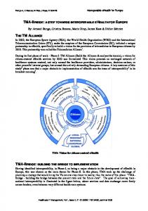
Figu ure 2. A compllete eHealth syystem 3. System Dessign The system thhat has been deesigned in this project is simiilar to that preesented in Figu ure 2. A complete system witth wireless sensoors or devices attached to a Set-Top-Box, directly connected to professionals or pattients’ families. To achieve the proposed gooals, two main n parts have deeveloped: the the t ZigBee deevices, and thee design of new w
82
ISS SN 1927-064X
E-ISSN 1927-06558
www.cccsenet.org/nct
Network and C Communication Technologies
V 1, No. 1; Junne 2012 Vol.
devicess that are not available on the market, oor devices thatt are not adap pted to ZigBeee. The Set-Topp-Box is developped with an A ARM processorr running on ann embedded Linux L distributiion. It is designned to be connnected to a televvision set and manage the sensor s networkk from it, witthout needing to install or have h more sysstems or devicess around the hoouse. All thee devices have been developeed with the JN N5148 module from Jennic (n now acquired by b NXP). It iss a 32-bit RISC microcontrolle m er with low power consumpttion. It has a loot of peripheraals, such as UA ARTs, ADC aand DAC converrters, DIO pinss, etc. Jennic has h also desiggned a ZigBeee Protocol Stacck certified byy the ZigBee A Alliance. Jennic provides a com mplete softwarre solution for developing ZiigBee compliaant applicationss. 3.1 Sofftware Developpment Home Automation is the main prrofile used in this project. The T developed d clusters are included in thhe Home mation specificaation of the ZigBee Alliancee. They are divvided into two sections: the general g commaands and Autom the com mmands of sppecific clusterrs. The basic functions havve been desig gned to discovver, read or w write the attributtes of any clusster. However, the clusters haave their speciffic commands. The clusters used u in this prroject are as folloows:
G Groups cluster, to discover, ad dd or remove a device from a group.
O On/Off cluster, with its comm mands to switchh on, switch offf or toggle thee light.
Level Control ccluster, to movee up or down tthe level of a light, either con ntinuously or in i steps.
A Analog Input clluster, with no specific comm mands.
Along with these cluusters, the deveelopment carrieed out includess the next deviices: Off Light Swiitch: Typical siimple switches to change thhe current statee of a light (sw witch on, switcch off or 1) On/O toggle)). 2) On/O Off Light: A siimple light, co ontrolled by a llight switch. 3) Dim mmer Switch: A dimmer whicch can change the level of a dimmable d ligh ht. 4) Dim mmable Light: A dimmable light controlled by a dimmer switch. s 5) Analog sensor: Anny sensor that gives g an analog value. In thiss project, a gallvanic skin ressponse meter. mmarize and coombine the co oncepts of ZigB Bee and the deeveloped appliication devicess, a table per ddevice is To sum presentted in Figure 3 showing the information i onn them.
Figure 3. Ziggbee informatiion of devices Anotheer feature devveloped is the binding proceess between devices. d A bind is a direct link l between an input cluster from an appliication object to t an output clluster of anothher application n object, for exxample, a link between the outtput on/off cluuster of a switcch and the inpput on/off clusster of a light device. This link is made thhrough a bindingg process. Thee devices ask for fo a binding annd the parent device d (a routeer or a coordinator) analyzes whether
Publishhed by Canadiann Center of Scien nce and Educatiion
83
www.ccsenet.oorg/nct
Netwo ork and Commuunication Technoologies
Vol. 1, No. N 1; June 20122
the clusters off both devices are compatiblle. If they are compatible, thhe parent respo onds with the address a and thhe endpoint of thhe bound devvice (the otherr device, withh a compatiblee cluster). Thiis informationn is kept in thhe binding table of the devicee. When some data should bbe transmittedd to the bindin ng devices, thee source devicce sends a framee per entry in tthe binding taable. If a switcch has three ligght entries in its binding tabble, it is able tto control three lights l independdently if they are in the sam me or different devices (only one ZigBee radio). This linnk is called one-tto-many bindiing (Figure 4a)). It is also poossible for onee light to be co ontrolled by seeveral switchess, commonly callled many-to-oone binding (Figure 4b). In thhis case, each switch adds th he same table entry. e
Fiigure 4. (a) On ne-to-many binnding; (b) Manny-to-one bind ding p is a pooint-to-point biinding; in otheer words, you have h to make a binding per pair of devices. This binding process If a switch haas to control thhree lights, th he binding process has to bee carried out three t times wiith the differennt lights and the same switch. H However, there is another way to address the t binding pro ocess. a devices relaated to lightinng have the Groups G cluster. This has beeen As can be seeen in the prevvious tables, all developed witth the intentionn of creating groups g of lightts, that is, a room could havee numerous ligghts. By addinng these indepenndent lights to a group, we could c light theem up all togetther without having h to switcch on the lightts one by one. The Groups cluuster allows adding an endpooint to a group in order to recceive all data addressed a to thhe ows removing aall groups or one o specific grroup from the groups g table, oor group in the sppecific endpoiint. It also allo asking for the groups an enddpoint belongs to.
Figure 5. G Group binding In the present case, each devvice performs a different acttion when it receives a messaage to add to a group. On onne ommand is sennt to a group, it hand, the lighht devices add the group to its groups table; so, when a switch-on co reaches all thee devices incluuded in that gro oup lighting thhem up. On thee other hand, when w an add-ggroup commannd is sent to a sw witch, it does not add the grroup ID to thee group table but to the bin nding one. Theereby, when thhe switch sends the t switch-on or switch-off command to tthe binding deevices, it sendss it to every group g and everry device stored in the binding table. This waay of binding iis called groupp binding, and is shown in Fiigure 5. When a or each device in the group. device is bounnd to a group, tthere is a singlle entry in the table; there is not an entry fo
84
ISS SN 1927-064X
E-ISSN 1927-06558
www.ccsenet.org/nct
Network and Communication Technologies
Vol. 1, No. 1; June 2012
3.2 Gateway Development Although the network can operate completely independently, the need to control it through an embedded system or a personal computer arises. Thereby, user applications based on any platform could be designed to manage the network. The proposed design is a gateway controller between the network coordinator and the computer. The communication channel is through a UART port of the microcontroller. The computer, meanwhile, establishes a virtual serial port, established through a USB port. The protocol has been designed with AT-like commands. There are commands from general to the most basic kind. There are some commands used to discover information on the devices: how many endpoints they have their input and output clusters, etc. There are also specific commands according to the clusters developed. There are specific commands to add a device to a group, to send on/off commands to the lights, to read a specific attribute of a device, etc. Table 1. Get simple descriptor command Command
GSDS
Parameters
NWKADDR, EP ID
Format
GSDS=XXXX.XX
Example
GSDS=6DB4.01
Table 2. On/Off unicast command Command
OOUC
Parameters
NWKADDR, SRC EP, DST EP, ON/OFF CLUSTER COMMAND
Format
OOUC=XXXX.XX.XX.XX
Example
OOUC=6147.02.01.02
The command shown in Table 1 is used to obtain information on a device. The command requests the simple descriptor of a specific endpoint of the device. The descriptor contains plenty of information, such as clusters (both input and output), the profile associated to the endpoint, the device indetifier, and so on. It is a general command, not specific of a profile. The command shown in Table 2, however, is a specific cluster command. It corresponds to the On/Off cluster. The command is used to send a unicast frame to switch on, switch off or toggle a light of a device. During the progress of this project, several devices have been designed in a parallel way. One example of them is the dimmable light device. This device is included in the Home Automation profile (according to ZigBee device profiles). The dimmable light device permits the user to modify the level of brightness in an incandescent light bulb. There are many ways of controlling this level, but we have chosen a digital control circuit. The level of brightness is controlled by four general purpose output pins of the ZigBee module. The circuit also has a 555 timer and a 4-bit counter. The 555 timer works as the counter clock. The output pins of the microcontroller control the initial value of the counter. Thus, when a zero crossing of the AC signal is detected, it resets the counter. The counter starts from the initial value (provided by the microcontroller pins) to zero, allowing the current to pass through the bulb. Once the counter has reached zero, the borrow signal of the counter stops the current flow into the bulb. The process, allowing the power signal to pass through the bulb at a time interval during the half-cycle, controls the level of brightness. This current flow is controlled by an optotriac. As the bulb has to be powered by the AC signal, this signal is also used for the rest of the circuit. We need to convert this AC signal into a DC signal, and lower its voltage. Therefore, in the complete schematic shown in Figure 6, a supply signal adaptation stage appears. This consists of a 9 V transformer and a rectifier bridge. The transistors in the center of the figure are used for the zero crossing detector system. The top of the image is another adaptation stage. We need to reduce the voltage from 9 V to the 3.3 V needed by the microcontroller.
Published by Canadian Center of Science and Education
85
www.ccsenet.oorg/nct
Netwo ork and Commuunication Technoologies
Vol. 1, No. N 1; June 20122
Figure 6. Dimmable light device scchematic
Figure 7.. Dimmable ligght device PCB B and case
86
ISS SN 1927-064X
E-ISSN 1927-06558
www.cccsenet.org/nct
Network and C Communication Technologies
V 1, No. 1; Junne 2012 Vol.
Apart from f the schem matic, the circu uit has been roouted into a PC CB. The PCB can c be shown in i Figure 7. It iis a PCB routed in two layers with most of its i componentts in surface mount m technolo ogy (SMD). Thhe device is coompleted by encapsulating thee PCB into a plug p case. Thiss case can be perfectly p plugg ged into any home h plug. The case is 15x5x33.5 cm (heighht, width, deptth). It is not ttoo high and future designs will be reduuced to make it more comforrtable. Anotheer device desiggned is a senso or that measurees galvanic skiin conductancee (also called galvanic g skin rresponse - GSR)). The GSR coonsists of appllying a direct current constaant voltage pro obe signal to the t skin. In m measuring skin coonductance, onne can disting guish two diffe ferent principlees: phasic and d tonic. A toniic value standds for an activityy that shows a certain degreee of continuitty over a time. The tonic co omponent of skkin conductance is the skin coonductance levvel (SCL). SCL L is obtained bby measuring the t total amoun nt of skin condductance and iis related to a person's overall arousal. In con ntrast to tonic values, a phassic value stands for the changge in skin condductance ulus elicits an orienting o respoonse, the within a short time period as a reacction towards a discrete stimuulus. If a stimu skin coonductance risses for a certaiin time periodd and then retuurns to normaal. This is calleed a skin condductance response (SCR).
Figuure 8. GSR prototype
Figure 99. GSR device schematic Publishhed by Canadiann Center of Scien nce and Educatiion
87
www.ccsenet.oorg/nct
Netwo ork and Commuunication Technoologies
Vol. 1, No. N 1; June 20122
The GSR prottotype can be sseen in Figure 8 and the devvice schematic is presented in n Figure 9. It has h two distincct parts: on one hand, h the adapptation stage fo or the signal innjected into thee body. You caannot inject a lot l of current iin order to avoidd electrocutingg the patient. On the other hand, there is the filtering stage. The siggnal we need iis within a smalll range of freqquencies. Moree specifically, the signal is below b 10Hz. Therefore, T the second stage iis the filter. Thiss filter is of Buutterworth typee and fourth orrder. It has beenn designed witth Sallen-Key topology.
Fig gure 10. Therm mometer schem matic d is a therrmometer, a geeneral and masssively used deevice to check k body temperaature. There arre And the last device several types of o body thermoometers: a) Mercuryy thermometer:: it is a non-d digital thermom meter that usess the expansio on of mercury contained in a glass tube. It is i very cheap bbut the mercury y is really harm mful if the therrmometer breaaks. b) Digital thhermometer: iit uses a therm mistor to checkk the temperatuure. It is a varriable resistancce that changees with temperatture. It is easyy to read the temperature t with an analog--to-digital conv verter and shoow it in a LCD D panel. mometer: it usees infrared technology, meassuring the enerrgy emitted by the tympanic membrane. c) Ear therm The type seleccted for the prroject is the digital one, usinng a thermistoor to measure the temperatuure. It is easy tto design and wee can take advaantage of the analog-to-digit a tal converter inncluded in the JN5148 microocontroller. Thhe thermistor hass been configuured in a bridgee as shown in tthe schematic of o Figure 10. The T thermomeeter has a buttoon, attached to a DIO pin of thhe microcontro oller. When it is pressed, thhe microcontro oller wakes upp and waits tw wo mperature. Afteer those minuttes, the converrter samples th he value and sends s it througgh minutes to staabilize the tem the network. 4. Results 4.1 Autonomoous Devices The followingg scenarios shoow the results concerning thhe autonomy of the devices and a their appliication in a reaal scenario. Alsoo presented aree some capturees from a sniffeer which has been a great hellp during deveelopment.
Scenarioo 1: Switch andd light binding
In this first sceenario, a simple switch and a simple light are presented. Both devices implement thee On/Off clusteer. The switch im mplements it ass an output clu uster and the liight as an inpuut cluster. In order o to bind thhem, the switcch and the light have h to send a bind request to o their parent ((in this case, thhe coordinatorr) with the infoormation on thiis cluster, and thhey receive a bbind response from f the coorddinator. This reequest is sent by b pushing onne button on thhe 88
ISS SN 1927-064X
E-ISSN 1927-06558
www.cccsenet.org/nct
Network and C Communication Technologies
V 1, No. 1; Junne 2012 Vol.
device.. When the biinding has beeen carried outt, if the same button is presssed on the sw witch device, tthe light device toggles one off its leds. In th his case, it togggles because thhe switch is co onfigured to seend a toggle coommand. a be configuured with two buttons, one too switch on annd the other to switch off the light. It can also
Figure F 11. Swiitch and Light binding captu ure b processs between thee devices Figure 11 shows a caapture from thee Wireshark snniffer. Here caan be seen the binding 89 and the coordinator (0x00000). The toggle commandds can be seeen in the with adddresses 0xd1189 and 0xe88 frames, checking they are ZigBee HA H compliant..
Figure 122. Report attribbute frame a also some reports of attrributes, becausse the light is configured to report changees in its attribuute. This There are attributte is the valuee of the light, and a in this casse, as the switcch device buttton has been pressed p twice tthere are two repports: one to nnotify that the light l has been switched on annd the other no otifying that itt has been swittched off. Figure 12 correspondds to the first report, when tthe light was switched s on, so o the report atttribute (Booleean type) was sett to true.
Sccenario 2: Dim mmer and dimm mable light binnding
This seecond scenariio is similar to t previous onne. The coorddinator has to o bind the dim mmer switch w with the dimmaable light. Thee clusters impllemented by tthem are the On/Off O clusterr and the Levvel Control cluuster. As above, the switch has them as outp put clusters annd the light as input clusters. They are bothh necessary: thhe on/off o switch on orr switch off thee light. The lev vel control onee, instead, provvides the cluster provides the ffunctionality to o the binding process p twice, one per functioonality to channge the light’s level of brighhtness. It is neecessary to do cluster because the cooordinator onlly makes one bbind per clusterr.
Figure 13. Dimmer aand Dimmablee Light binding g capture mplemented by pressing the same button on o the device. First, you preess for a This biinding processs has been im bindingg, and when it has been carriied out, you prress for the seccond one (see capture c in Figuure 13).
Publishhed by Canadiann Center of Scien nce and Educatiion
89
www.ccsenet.oorg/nct
Netwo ork and Commuunication Technoologies
Vol. 1, No. N 1; June 20122
Figuree 14. Level conntrol move com mmand The followingg frames show w the sending of o move comm mands (0x01) to t increase the light brightneess and the stoop command (0xx03), to halt thee increases. Th here is only onne report becauuse it is config gured to notify a change wheen it reaches a sttable value; inn this case, wh hen the light reeceives the stoop command. Figure 14 corrresponds to thhe first commandd frame. It is a move commaand, so a modee (increase or decrease) d and a step must be indicated (botth bytes of data 0x00 and 0x00a, respectivelly). This step is the increasee or decrease per second -inncrease, in thiis b It iis stopped with h the stop comm mand (0x03). case- in light brightness.
Scenarioo 3: Analog sennsors
Fiigure 15. Analoog sensor captture In this scenariio there is no bbinding. The device d has beeen developed too obtain samples of an analoog sensor everry five seconds. It I samples andd converts the value v to digitaal and then sennds it to the coo ordinator in a report r frame, aas is shown in Fiigure 15. 4.2 Gateway: Controlling thhe Network from a PC w several funcctions that can be conductedd from the serial port of a PC C. The capturees The gateway scenarios show from the seriaal port are also presented.
Scenarioo 1: Collecting information of devices
This scenario shows the iniitial need to deevelop user appplications: to discover whicch devices are in the networrk his need, theree are several commands c thaat can be sent to discover thhe and their infoormation. In orrder to meet th endpoints, thee clusters or thee attributes of a device. The value of an atttribute can be also a requestedd from a devicee. The notificatioon of a new ddevice reaches the serial portt. The endpoinnts it has are asked a for, and the response iis one endpoint with w ID=0x01. Then the sim mple descriptorr of that endpooint is requesteed, which incluudes the profille associated to the t endpoint, tthe device id an nd the input annd output clustters. The respo onse is that thee endpoint 0x001 of the device with address 00xdc45 has associated the H Home Automattion Profile (0x x0104). It is an a On/Off Lighht 0 and hhas two input clusters and ttwo output cluusters: the On//Off cluster (0x0006) and thhe (DeviceID = 0x0100) Groups clusteer (0x0004). A After this, the device d is askedd for the attribbutes of the clluster 0x0006,, and it has onne attribute with ID=0x0000 annd it is of Boolean type. Tabble 3 presents the t commands exchanged thrrough the seriaal port terminal while w Figure 116 shows data sent by radio. way commandds in Scenario 1 Table 3. Gatew DIR IN OUT IN OUT IN OUT IN
90
PR ROTOCOL COMMAND ND DEV=DC45.000158D00000F2 2588.8E GE EPS=dc45 SE EPS=DC45.01.01 GS SDS=dc45.01 SSDS=DC45.01..0104.0100.00 0.02.0006.00044.02.0006.00044 AT TDC=dc45.01.01.0006.0000.02 AT TDR=DC45.011.0006.01.0000 0.10
EX XPLANATION N New Device Get Endpoints off 0xdc45 Get EPs Responsse Get Simple Descriptor Get Simple Desc Response Atttributes Discovvery Attt Discovery Reesponse
ISS SN 1927-064X
E-ISSN 1927-06558
www.cccsenet.org/nct
Network and C Communication Technologies
V 1, No. 1; Junne 2012 Vol.
Figure 16. Coollecting inform mation capturee
Sccenario 2: Uniicast transmisssion
The seecond scenarioo includes seveeral commandss that can be sent s to each device d as a uniicast transmisssion. For examplle, we can swiitch on a light or increase thee value of a diimmable light,, or even ask for f the present value of an anallog sensor suchh as a galvanicc skin responsee sensor. As inn the previous scenario, and in i Figure 17 shhows the whole process p from tthe serial port terminal t and radio, respectivvely. 4 Gateway com mmands in Scenario 2 Table 4. DIR
PROTOC COL COMMA AND
E EXPLANATIO ON
IN
NDEV=1F F7A.00158D00 0001108DF.8C C
N device New
IN
NDEV=FF F12.00158D00 0000F2588.8E E
N device New
IN
NDEV=9F F7F.00158D00 0000F2475.8E E
N device New
OUT
OOUC=fff12.01.01.02
O Off Toggle command to 0xff12 On 0
IN
ATRP=FF F12.01.0006.00 000.10.01
A Attribute Reporrt
OUT
DMSU=9ff7f.01.01.00.0a.0000
D Dimmer Move (UP) Step (0xx0A) to 0x9f7ff
IN
ATRP=9F F7F.01.0008.00 000.20.0A
A Attribute Reporrt
OUT
ATRD=1ff7a.02.01.000cc.0055
Read Attribute 0x0055 of clusster 0x000c, off device R 0 0x1f7a
IN
ATRR=1F F7A.01.000C.0 0055.39.0000007C9
A Attribute Read Response
Figure 17. U Unicast transm mission capture
Sccenario 3: Grooups
Anotheer important feeature is the po ossibility of addding devices to groups. It is i possible to send s a multicaast frame so that all devices in that group willl receive it. Beforehand, thee devices should be added too a group. The protocol me commandss for adding, removing r or ddiscovering thee groups of a device. This scenario s combbines the has som actionss of the gatewaay and the actio on of the switcch over a groupp bound to it. As prevviously mentiooned, the first step required iis to add the devices d to a gro oup. In this casse, there are tw wo lights and a switch, s and theey all are added to the groupp ABCD. The lights l include the t groups in their t groups taables and the swiitch in its bindding table. Thee OOGR comm mand sends a switch s on com mmand to the grroup. The lighhts added to that group changee their light to on and then ssend a report with w the Booleean attribute too true (0x01). The last two repports are causeed by the switcch. When the sswitch is presseed, it sends a toggle commannd to its boundd devices. In this case, the bouund device is a group, and bboth light devices switch offf the light andd send the connsequent report. Table 5 and Figure 18, oncee again, presennt all the processs.
Publishhed by Canadiann Center of Scien nce and Educatiion
91
www.ccsenet.oorg/nct
Netwo ork and Commuunication Technoologies
Vol. 1, No. N 1; June 20122
Table 5. Gatew way commandds in Scenario 3 DIR
PR ROTOCOL C COMMAND
EXPL LANATION
IN
ND DEV=A6C4.000158D000011 108DF.8C
New device
IN
ND DEV=A8FC.000158D00000F F2475.8E
New device
IN
ND DEV=8E10.000158D00000F2588.8E
New device
OUT
GR RAD=a6c4.011.01.abcd
G Requestt Add Group
IN
GR RAR=A6C4.A ABCD.00
Add Group G Respon nse (Success=00x00)
OUT
GR RAD=a8fc.01.01.abcd
Add Group G Requestt
IN
GR RAR=A8FC.A ABCD.00
Add Group G Respon nse (Success=00x00)
OUT
GR RAD=8e10.011.01.abcd
Add Group G Requestt
IN
GR RAR=8E10.A ABCD.00
Add Group G Respon nse (Success=00x00)
OUT
OO OGR=abcd.011.01
Switcch ON to group p ABCD
IN
AT TRP=D300.011.0006.0000.10 0.01
Attribbute Report
IN
AT TRP=8E10.011.0006.0000.10 0.01
Attribbute Report
Figure 18. G Groups capture
Figure 19.. SetTop Box aand some wirelless devices 4.3 System Inttegration All these deviices have beenn integrated intto the SetTop Box mentioneed above. The complete systtem is shown iin Figure 19, inccluding the dessigned devices as well as othher devices by different manu ufacturers. We have tested thhe end devices with w our coorddinator and oth hers to verify that they are interoperable. In addition, network traffiic captures havee sniffed to veerify that they y meet the staandard and to dismiss a lott of modules that have beeen acquired and are not ZCL ccompatible. Moreover, M the S SetTop Box inccludes an appllication softwaare that enablees w is watching TV. the user to maanage the wirelless network while
92
ISS SN 1927-064X
E-ISSN 1927-06558
www.ccsenet.org/nct
Network and Communication Technologies
Vol. 1, No. 1; June 2012
4.4 Satisfaction Test We have also carried out several questionnaires with different people in terms of age and technological knowledge in order to analyze whether we are working in the right way. Although the questionnaire was simple, it was sufficient to test the system. The responses of the questionnaire had to be between the values of 1 and 5 (1 for “disagree”, 5 for “strongly agree”). Among all the questions asked, the three most important are highlighted below. The users were asked if: The software application was easy to use. • Creating the WSN was simple. • The system is useful. • We interviewed some 25 people and the results are presented in Table 6. Table 6. Test results Questions
Mean value
Simplicity of User Application
3.8
Simplicity of creating the WSN
3.6
Utility and Usability
4.35
Complete System Mean value
3.92
We have come to the conclusion that people with higher technological knowledge are more critical than others with less expertise. Nevertheless, people believe that the project is extremely useful. According to the general mean value, the system is being developed in the right way but a great effort should be made to make it easier to use. 5. Discussion
As shown throughout the article, there is a growing need for health services. Life expectancy is increasing as well as the number of illnesses, which is why telehealth systems are highly demanded by users, professionals and governments. Our goal as developers is to design systems that help people without involving major changes in their lifestyle or without a long training being needed to use it. To avoid these two aspects, adaptive systems are needed. This means having systems that are self-configuring in order to require as little user intervention as possible, thus enhancing its ease of use, one of the goals of this project. Apart from this feature, another important goal was to develop a system based on a standard, thereby promoting interoperability between devices by different manufacturers. Firstly, a preliminary state-of-the-art analysis of wireless technologies was carried out until ZigBee was selected. ZigBee is a technology that is taking off slowly, step by step. Its entry into the market is hard because it is open standard. There are other protocols that are owned by manufacturers of consumer electronics causing their prompt take-off in the market. Even so, ZigBee has the skills and features necessary for a wide deployment of sensors in a network regardless of the application type (home automation, security, healthcare, safety…). As presented in the results section, specific and general application features have been developed. These features are: binding, in order to decentralize network management and allow independent operation of devices, and the ability to create groups of devices to manage them as a group rather than individually. Despite enabling independent operation, the system can be controlled by a user application. The idea is to have an intuitive and easy-to-use application that manages the network. For this reason, a gateway has been also developed allowing information exchange between the network coordinator and any embedded device. A user interface can be designed to run on any platform or operative system and be able to connect with the network through a serial communication port. This provides many possibilities as the user application can use different technologies. In this case, the embedded device could act as a bridge between the sensor network based on ZigBee and the other networks. The gateway developed is oriented to the described scenarios but can easily be expanded or customized to fit in any design. There are similar types of systems on the market like the one presented in this article. One example is the AlertMe system, which is a complete product for home automation and control. It has sensors that detect if a window or a door has been opened, devices to turn on electric appliances, motion sensors, and so on. It is a scalable system throughout its range of products, but it offers no interoperability with other devices. It is a closed Published by Canadian Center of Science and Education
93
www.ccsenet.org/nct
Network and Communication Technologies
Vol. 1, No. 1; June 2012
product, based on the first ZigBee release. So if you need a particular device and it is not developed by the manufacturer, you cannot integrate a device from another manufacturer in the AlertMe system. Another company with similar ZigBee compliant products is Simplehomenet, a company experienced in different technologies such as X10, Insteon or ZigBee. It markets gateways of these technologies, but they have some products that still have not been adapted to ZigBee. However, products that are already adapted meet the latest ZigBee release. There are not a great number of products on the market. There are no complete or customized systems that can interoperate with other devices, or systems that anyone can install at home regardless of their technological knowledge. New technologies are increasingly appearing, not only more, but better ones. This prevents the development of systems with previous technologies and they become unfinished and unsupported systems. We suggest that more technologies are not needed and we have to exploit existing ones. In addition, this fast leaping from one technology to another does not provide sufficient time for companies to recover their investment, causing a lack of interoperable systems that requires more effort. And after all, this is what is needed to create value-added services. The expansion of profiles used in the devices is proposed as a future line of work. Other future work could be the design of new devices oriented to healthcare, or the adaptation of designed ones to the ZigBee Pro standard. And finally, as regards software development, we propose the design of an intuitive and easy-to-use user application. The application could be adaptable, depending on the collective to which it is oriented. 6. Conclusions
As a final reflection, below is a review of the aims proposed at the beginning of this article that have been fulfilled. As regards the implementation of ZigBee in application devices, several scenarios have been presented as a result of the developments carried out. These scenarios present, in a clear and simple way, everything developed in the devices to attain their use in real environments. These developments are the base or the mainstay for future development of specific applications. It is the beginning of a long road towards a complete system that provides value-added services based on a unique technology. Likewise, the development of a gateway making it possible to connect the system to different systems has been successfully implemented. The gateway can be extended depending on the level of specificity needed, thus enabling easier use in more specific future applications. The scenarios presented above are based on some tests performed with several devices of both home automation and health profiles. Since it is a work in progress, we have started studying ZigBee standard by developing general devices (such as switches and dimmers). It is a simple but effective way of studying the standard in order to establish knowledge. Health sensors and devices are being designed in a parallel way to be integrated in the system as soon as possible. So, the work presented is the basis of the complete system and the progress of a long future work including integration of new health devices as well as an user application to control the whole network. The main aim is to produce a complete system for future deployment in patients’ homes. References
Akematsu, Y., & Tsuji, M. (2009). Economic effect of eHealth: Focusing on the reduction of days spent for treatment. 11th International Conference on e-Health Networking, Applications and Services. pp. 14-20. Cabral, J. J., & Kim, Y. (1996). Multimedia systems for telemedicine and their communications requirements. IEEE Communications Magazine , 34, pp. 20-27. http://dx.doi.org/10.1109/35.526884 Chadwick, P. (2007). Regulations and Standards for Wireless applications in eHealth. 29th Annual International Conference of the IEEE Engineering in Medicine and Biology Society. pp. 6170-6173. Chien, C., Xu, Z., & Molloy, S. (2010). Topics in integrated circuits for communications. IEEE Communications Magazine , 48, 74. http://dx.doi.org/10.1109/MCOM.2010.5439079 Chuang-Chien Chiu, T.-W. S.-C.-C.-Y. (2006). A Wearable e-Health System with Multi-functional Physiological Measurement. World Congress on Medical Physics and Biomedical Engineering, 14, 429-432. De, M. G. (2005). Trends in Health Telematics: Electronic Health Records in an Intelligent and Communicating Environment. Universal Access in Health Telematics. Lecture Notes in Computer Science , 3041, pp. 1393-1397. Detmer, D., Bloomrosen, M., Raymond, B., & Tang, P. (2008). Integrated Personal Health Records: 94
ISSN 1927-064X
E-ISSN 1927-0658
www.ccsenet.org/nct
Network and Communication Technologies
Vol. 1, No. 1; June 2012
Transformative Tools for Consumer-Centric Care. BMC Medical Informatics and Decision Making, 8, 1-14. http://dx.doi.org/10.1186/1472-6947-8-45 Farshchi, S., Pesterev, A., Nuyujukian, P., Mody, I., Judy, J., & Bi,F. (2007). An Embedded Sensor/System Architecture for Remote Biological Monitoring. IEEE Transactions on Information Technology in Biomedicine , 11, 611-618. http://dx.doi.org/10.1109/TITB.2007.897600 Gibbons, M. (2008). Disparities and eHealth: Achieving the promise and the potential. In Gibbons, & M. Christopher, eHealth Solutions for Healthcare Disparities. New York: Springer. pp. 154-164. Gomez, C., & Paradells, J. (2010). Wireless home automation networks: A survey of architectures and technologies. IEEE Communications Magazine, 48, 92-101. http://dx.doi.org/10.1109/MCOM.2010.5473869 Hine, N., Petersen, F., Pluke, M., & Sund, T. (2008). Standardization work on personalized eHealth systems. 30th Annual International Conference of the IEEE Engineering in Medicine and Biology Society. pp. 1518-1520. Hui, Z., Yanting, G., & Xue, W. (2010). Theoretical and Empirical Study on the Relationship between Household Health Investment and Government's Public Health Investment. International Conference on Management and Service Science. pp. 1-4. Hwang, K., In, J., Park, N., & Eom, D. (2003). A design and implementation of wireless sensor gateway for efficient querying and managing through World Wide Web. IEEE Transactions on Consumer Electronics , 49, 1090-1097. http://dx.doi.org/10.1109/TCE.2003.1261201 Iakovidis, I., Le, D. O., & Karp, P. (2007). Biomedical Engineering and eHealth min Europe - Outcomes and Challenges of Past and Current EU Research Programs. IEEE Engineering in Medicine and Biology Magazine , 26, 26-28. http://dx.doi.org/10.1109/MEMB.2007.364925 Iluyemi, A., & Briggs, J. (2009). eHealth and Global Health: Investments Opportunities and Challenges for Industry in Developing Countries. Electronic Healthcare. Lecture Notes of the Institute for Computer Sciences, Social Informatics and Telecommunications Engineering , 1, 182-185. Krol, M. (1997). Telemedicine. IEEE Potentials, 16, 29-31. http://dx.doi.org/10.1109/45.624339 Bandyopadhyay, L. K., S. C. (2010). ZigBee Technology: A Unique Wireless Sensor Networking Solution. Wireless Communication in Underground mines, 153-174. Le, M. B., & Ray, P. (2009). Issues en E-Health Cost Impact Assessment. World Congress on Medical Physics and Biomedical Engineering, 25/12, 223-226. IFMBE Proceedings. Lymberis, A., & Dittmar, A. (2007). Advanced Wearable Health Systems and Applications - Research and Development Efforts in the European Union. IEEE Engineering in Medicine and Biology Magazine , 26, 29-33. http://dx.doi.org/10.1109/MEMB.2007.364926 Mauksch, M. W. (1987.). The Aging Population: The New Growth Market. Ageing International, 14(2), 23-24. http://dx.doi.org/10.1007/BF02999842 McAdams, E., Krupaviciute, A., Gehin, C., Dittmar, A., Delhomme, G., Rubel, P., … McLaughlin, J. (2011). Applications to Medical Diagnostics/Monitoring. In Bonfiglio, A., & Rossi, D. d. Wearable Monitoring Systems. Springer. Nitzkin, J. (1996). Technology and health care-driving costs up, not down. IEEE Technology and Society Magazine, 15, 40-45. http://dx.doi.org/10.1109/44.536300 Paul, D., Pearlson, K., & McDaniel, R. J. (2009). Assessing technological barriers to telemedicine: technology-management implications. IEEE Transactions on Engineering Management , 46, 279-288. http://dx.doi.org/10.1109/17.775280 Piniewski, B., Muskens, J., Estevez, L., Carroll, R., & Cnossen, R. (2010). Empowering Healthcare Patients with Smart Technology. IEEE Computer Magazine , 27-34. Poon, C., & Zhang, Y. T. (2008). Perspectives on High Technologies for Low-Cost Healthcare. IEEE Engineering in Medicine and Biology Magazine , 27, 42-47. http://dx.doi.org/10.1109/MEMB.2008.923955 Sheng, O., Hu, P. H., Wei, C. P., & Ma, P. C. (1999). Organizational management of telemedicine technology: conquering time and space boundaries in health care services. IEEE Transactions on Engineering Management , 46, 265-278. http://dx.doi.org/10.1109/17.775279
Published by Canadian Center of Science and Education
95
www.ccsenet.org/nct
Network and Communication Technologies
Vol. 1, No. 1; June 2012
Song, G., Zhou, Y., Zhang, W., & Song, A. (2008). A multi-interface gateway architecture for home automation networks. IEEE Transactions on Consumer Electronics, 54, 1110-1113. http://dx.doi.org/10.1109/TCE.2008.4637595 Sudhahar, S., Vatsalan, D., Wijethilake, D., Wickramasinghe, Y., Arunathilake, S., Chapman, K., et al. (2010). Enhancing Rural Healthcare in Emerging Countries through an eHealth Solution. ETELEMED '10. Second International Conference on eHealth, Telemedicine, and Social Medicine. pp. 23-29. Vasilyeva, E., Pechenizkiy, M., & Puuronen, S. (2005). Towards the framework of adaptive user interfaces for eHealth. 18th IEEE Symposium on Computer-Based Medical Systems. pp. 139-144. http://dx.doi.org/10.1109/CBMS.2005.101 Wells, P. (2002). Can technology reduce health care costs? Engineering Management Journal, 12, 194-200. http://dx.doi.org/10.1049/em:20020410 Yan, H., Huo, H., Xu, Y., & Gidlund, M. (2010). Wireless sensor network based E-health system: implementation and experimental results. IEEE Transactions on Consumer Electronics, 56, 2288-2295. http://dx.doi.org/10.1109/TCE.2010.5681102
96
ISSN 1927-064X
E-ISSN 1927-0658