Techniques to compress FPGA bit-streams have been widely studied. The method in ... configuration data in order to reduce the storage requirements and perform de- ... facility whereby several registers in a column could be written with the same ... data that resides in a register is called a frame, which is the smallest unit of.
A Configuration System Architecture Supporting Bit-stream Compression for FPGAs Marco Della Torre† , Usama Malik†‡ and Oliver Diessel†‡ †
School of Computer Science and Engineering University of New South Wales Sydney, Australia ‡ Embedded, Real-time, and Operating Systems (ERTOS) Program, National ICT Australia {marcodt, umalik, odiessel}@cse.unsw.edu.au Abstract. This paper presents an investigation and design of an enhanced on-chip configuration memory system that can reduce the time to (re)configure an FPGA. The proposed system accepts configuration data in a compressed form and performs decompression internally. The resulting FPGA can be (re)configured in time proportional to the size of the compressed bit-stream. The compression technique exploits the redundancy present in typical configuration data. An analysis of configurations corresponding to a set of benchmark circuits reveals that data that controls the same types of configurable elements have a common byte that occurs at a significantly higher frequency. This common byte is simply broadcast to all instances of that element. This step is followed by byte updates if required. The new configuration system has modest hardware requirements and was observed to reduce reconfiguration time for the benchmark set by two-thirds on average.
1
Introduction
The high latency of configuration places a significant limitation on the applicability and overall performance of Field Programmable Gate Arrays (FPGAs). This limit is most evident when reconfiguration is performed as part of the overall processing mechanism, such as in dynamically reconfigurable systems. In this paper the background, investigation and design of an enhanced configuration system to reduce this limitation is presented. Our results demonstrate significant performance improvements over currently available devices. The new configuration system reduces the time required to configure an FPGA for typical circuits, requires little additional hardware to that available in current models, and therefore increases the possible applications of FPGAs, while enhancing the performance of systems in which they are already employed. The technique presented in this paper reduces the (re)configuration time of an FPGA circuit by reducing the amount of configuration data that needs to be loaded onto the device via its configuration port. Data compression is achieved by exploiting the regularities present within typical configurations. An analysis of a set of benchmark circuits from the DSP domain reveals that fragments of
configuration data controlling the same type of FPGA resources tend to be similar with at least one byte occurring with a high frequency. This characteristic of typical configurations suggests the following compression technique: partition the configuration data into sets that control the same type of resources in the device; broadcast the most frequent byte in each set on all instances of that resource; then selectively load any bytes that differ from the byte previously broadcast. Using this technique, we observed a two-third reduction in reconfiguration time for the benchmark set. Techniques to compress FPGA bit-streams have been widely studied. The method in this paper differs mainly in two respects: it shows that a broadcastbased compression technique can be applied on the configurations of a high density FPGA and, in contrast to the previously published methods, it requires significantly less hardware resources to decompress and distribute the data in the configuration memory. These issues are discussed in Section 2. We follow that with an analysis of the configuration data corresponding to typical DSP circuits, which motivates the broadcast-based configuration system presented in Section 4. The proposed model is analysed in Section 5, followed by conclusions and a reference to future work.
2
Related Work & Background
The main focus of this research is on techniques that reduce the reconfiguration time of an FPGA by reducing the amount of configuration data that must be transfered to the memory. This differs from those techniques which compress configuration data in order to reduce the storage requirements and perform decompression before data is loaded into the memory array (e.g. [3]). Apart from compression, architectural techniques such as multi-context FPGAs have also been proposed as a solution to high reconfiguration latency (e.g. [9, 18]). These methods, however, demand significant memory resources. Other proposals, such as pipelined [17] and wormhole [15] reconfiguration are only applicable to specialised FPGA models. Within the work on compression we identify two categories: the methods in the first category propose special memories that directly accept compressed data. The XC6200 was an earlier FPGA of this type and offered a wildcard facility whereby several registers in a column could be written with the same data at once [20]. Luk et al. showed that wildcarding can provide near constanttime reconfiguration for highly regular circuits but can be inefficient for irregular cases [10]. Hauck et al. presented an algorithm that uses wildcard effectively and reduced reconfiguration time for a set of benchmark circuits to almost a quarter [2]. As FPGAs grew in density, the RAM-style configuration memory had to be compromised since it requires significant hardware resources. The configuration memory in Virtex is implemented as a large number of shift registers that can be individually addressed [19]. Several researchers have investigated compression techniques for this model and achieved 20-85% reduction in bit-stream size
for various benchmarks. Dandalis et al. studied a dictionary-based compression technique and found that it demands significant on-chip memory to store the dictionaries [1]. The method presented by Li et al. is LZ-based, which has modest on-chip memory requirements but requires a large number of parallel wires across the device [8]. Both of these methods are therefore viewed as impractical for large devices. Recently, Ju et al. have described algorithms that exploit both inter- and intra- configuration regularities [14]. However, the required hardware decompressor is not detailed. Our previous research efforts focused on reducing the amount of configuration data that must be loaded for a circuit by making use of configuration fragments that are already present on-chip [11]. An analysis of a set of benchmark circuits showed that significant configuration re-use is possible if the memory allows byte-level access to its registers. However, for a large device, the RAM style, fined-grained access to configuration memory presents with significant address data. Moreover, a RAM style implementation is costly in terms of the wires that are needed to transfer data directly to byte-sized registers. The above issues were discussed in [12] and a new configuration architecture was presented that allowed byte-level access to configuration memory at a significantly lower cost in terms of the address and wiring overheads. The proposed system implemented a strategy where on-chip data was read into an internal buffer, was modified and finally written back to its destination. The method presented in this paper is an attempt to overcome the increased power consumption incurred due to excessive data movement in the read-modify-write strategy. Moreover, the current memory does not require the user to know the previous configuration state of the FPGA. This architecture is partly inspired by the XC6200’s wildcarding mechanism. The main contribution of the present work is that it shows the benefits of such a model, even for high density FPGAs, at negligible additional hardware cost.
3
Empirical Analysis
Compression techniques depend upon the regularities that exist within input data. This section provides an empirical analysis of the frequency distribution of the data within a typical configuration. We first present our assumed device model, a Virtex FPGA [19]. This device was chosen because it is widely used in academia and industry alike. Moreover, Virtex provides a low-level interface to its configuration data, which aids analysis [5]. A Virtex device consists of c columns and r rows of logic and routing resources segmented into so-called configurable logic blocks (CLBs). There are 48 configuration shift-registers per column which span the entire height of the device. Each register configures a portion of a column of the FPGA resources. The data that resides in a register is called a frame, which is the smallest unit of configuration. The number of bytes in a frame, f , depends on the number of rows in the device (e.g. for an XCV100, c = 30, r = 20 and f = 56).
The user supplies the configuration data through an 8-bit wide input port at a configuration clock frequency of at most 66MHz. If the overhead data required due to pipelining of the configuration process is neglected, the time needed to (re)configure the device is directly proportional to the amount of data that is to be transferred to its configuration memory. For an XCV100, a complete configuration consists of 97,652 bytes, which can be loaded in 1.5ms. The configuration delay for the largest member of the family is at least 11.6ms. When an FPGA is reconfigured to implement the various phases of a high-performance, iterative algorithm, e.g. real-time image processing, the size of these overheads can render dynamic reconfiguration infeasible. Low latency reconfiguration techniques are therefore essential to make use of this method. The process to load configuration data onto a Virtex device uses a DMA approach and works as follows. Load the address of the first frame and the number of consecutive frames that are to be updated. Next, load the required frames onto the device byte by byte. Finally, supply a pad frame in order to flush the internal pipeline. This process needs to be repeated for each block of contiguous frames. The limitations of this addressing model for fine-grained access to the configuration memory were discussed in [12]. Several researchers have considered the problem of re-ordering Virtex frames so as to exploit the similarity between successive frames [8, 14]. We ran several experiments in which various frame orderings were considered. For each ordering, we determined the number and frequency of the unique bytes in the successive frames as this impacts upon any compression technique. Not surprisingly, maximum redundancy in data was observed when the ordering was such that frames at the same offsets within logic columns, which configure the same resources, were considered together. We describe this experiment in detail. 3.1
Experiment 1
Ten common circuits from the DSP domain were considered (Table 1). Table 2 also provides some parameters of the technology-mapped netlists of these circuits indicating their resource requirements. These high-level parameters were used because the CAD tool does not completely report on the low-level utilisation of the device (e.g the number of programmable interconnect points used). These circuits were mapped onto an XCV100 using ISE5.2 ([4]). This device was chosen because it was the smallest Virtex that could fit all circuits. The total number of 4-input look-up-tables (LUTs) in an XCV100 is 2,400 and the number of bonded IO blocks is 180. Thus, most of the circuits used the available resources sparsely. The circuits were synthesised for minimum area, and the configuration files corresponding to these circuits were generated. These bit files were converted into ASCII for further processing using JBits [5]. In this analysis only 1440 (48×30) frames corresponding to the CLB and switch configurations were considered. The remaining 170 frames in the device correspond to the RAM and IO blocks and are not organised into bundles of 48. In order to simplify our analysis, these were initially ignored.
In the next step, each configuration was partitioned into 48 sets. The ith , 1 ≤ i ≤ 48, set consisted of frames that are located in the ith position within each column. We refer to these frames as having the same column offset. Each set, containing 30 frames, was further partitioned into 56 subsets such that the jth subset contained the jth byte from each frame. The size of each of these subsets was thus 30 bytes. The individual bytes occurring in each subset were examined and their frequency within the subset recorded. From this, the average number of unique bytes and their average frequency distribution was determined. The results are shown in the second column of Table 1. The second column lists the average number of unique bytes at a particular byte position within all frames at the same offset within the CLB columns. The next two columns list the highest and second highest frequencies recorded for individual bytes in these sets. The results show that a single byte value has a frequency of more than 20 on average. In other words, across all frames with the same column offset, at the same byte offset within the frame, just a few bytes values occur on average, and just one of these dominates each set. It was also found that these common bytes differ from row to row. It should be noted that DCT and IIR, the two largest circuits, had much less regularity in their configuration data. A high level of regularity was observed in the above experiment because frames at the same column offsets configure the same types of resources. By performing similar experiments as above, it was found that frames at different column offsets did not exhibit high degrees of similarity. As a consequence, the architecture outlined in the next section considers frames at the same column offsets as a unit. As for the non-CLB frames, it was found that consecutive frames contain the greatest similarity.
Circuit
Experiment 1 Experiment 2 #Unique Highest 2nd Highest #Unique Highest 2nd Highest bytes Freq. Freq. bytes Freq. Freq. ammod [4] 3 27 1 7 16 5 bfproc [13] 3 26 1 7 16 5 ccmul [13] 3 27 1 7 16 5 cic3r32 [13] 3 27 1 7 16 5 cosine LUT [4] 4 26 1 7 15 5 dct [4] 6 20 3 11 13 4 ddsynthesiser [13] 2 28 1 6 16 5 dfir [4] 2 28 1 6 16 5 fir srg [13] 2 28 1 7 16 5 iir [13] 5 22 3 9 15 4 Table 1. Results for Experiments 1 & 2.
3.2
Experiment 2
The previous experiment attempted to understand byte distributions across the device. This experiment attempts to find regularities vertically within the frames. The objective of this experiment was to determine the average number and distribution of the unique bytes within the frames as it is this similarity that has previously been exploited in [8]. The ten configurations were considered again. Each frame in each configuration was considered. The number of unique bytes in each frame was considered and the frequency table corresponding to each frame was determined. The results are shown in the second column of Table 1, which shows that while regularities exist within the frames, they are not as pronounced as across the frames. This result is also expected as a frame contributes 18 bits, as opposed to some multiple of 8 bits, to each row of resources [19]. 3.3
Summary
The results of the above experiments can now be summarised: for typical Virtex configurations, CLB frames at the same column offsets are likely to contain the same data at a particular byte offset with a single common byte occurring with a high frequency within the frames; consecutive non-CLB frames have greatest similarity; and, for the same configurations, intra-frame regularity is significantly less than inter-frame regularity.
4
A New Configuration System Architecture
The proposed scheme is divided into two stages. The first stage configures the non-CLB frames (IOB, BlockRam Interconnect and Centre frames). The second stage configures the CLB frames. During the CLB stage, configuration data is transferred as a block to sets of frames with the same offset within the CLB columns, whereas in the non-CLB stage, the data is transferred as a block to adjacent frames. In the CLB stage, the most common byte is broadcast to every frame in the current set, followed by byte updates to those locations that differ from the broadcast data. The approach followed differs from the current Virtex configuration method, in which adjacent frames are loaded one after another. The system proposed here allows commonality in the blocks of data being sent to frames to be eliminated. This section presents the new configuration system architecture with an XCV100 device in mind. The next section includes a discussion of the scaling of this model to larger devices. Data is buffered from the byte-wide input port and then transferred to the configuration memory in 30-byte packets. We use the term byte set to describe these packets, which are a basic unit of configuration in the proposed design. Although the design described in this section caters for 32 bytes in a packet, our template device only requires the use of 30 at a time. A byte set is prepared by first supplying the most commonly occurring beneficiary byte, which is broadcast to all 30 locations in the byte set. After this, the
user specifies a 4-byte modification vector, in which each bit indicates whether a byte in the byte set is to be modified or not. If any bytes are to be modified, the user inputs these in sequence to complete loading the byte set. In XCV100, a byte set can thus be prepared in as few as 5 cycles (1 for the beneficiary byte and 4 for the modification vector) and as many as 34 cycles (29 additional cycles for the non-beneficiary bytes). Once a byte set is prepared it is distributed throughout the device where the configuration data is shifted into the appropriate frames in parallel. In order to completely configure the selected frames, 56 byte sets, corresponding to the number of bytes within a frame, must be prepared and shifted to the frame registers. These 56 byte sets are subsequently referred to as a frame set . For all Virtex family members, 48 frame sets are needed to completely configure the CLB columns and 6 frame sets are needed to configure the non-CLB frames. Partial configuration is a method for reconfiguring portions of an FPGA instead of the complete device. In Virtex devices, users typically reconfigure one or more vertical bands of the device in order to swap one core and its interconnect for another. The Virtex family supports partial configuration by allowing contiguous frames within a range of frame addresses to be loaded. In this proposal, the user is required to load those frame sets that “touch” the configuration registers spanned by the core that is to be loaded. Usually this will mean all 48 frame sets must be loaded. To support partial configuration, a couple of mechanisms provide finer control over which parts of the configuration memory are updated and thus over how much data must be loaded. First, the range of frame set addresses that is to be loaded is specified by giving an initial frame set address (F SAi ) and a final frame set address (F SAF ). Second, prior to loading each frame set, a 4-byte F SAwe vector, which enables writing to the individual frames within the set, must be loaded. For example, if some incoming core requires that the configuration memory of frames 0–15 and 32–47 in column 12 and frames 12–23 and 36–39 of column 13 be updated, we would load two frame set ranges, the first spanning frame sets 0–23, and the second frame sets 32–47. For frame sets 0–11, all bits of the F SAwe vector would be cleared except for the 12th, and for frames sets 12–15 the 13th bit would be asserted as well, then the 12th bit would be cleared for frame sets 16–23, and so on. 4.1
Main Controller
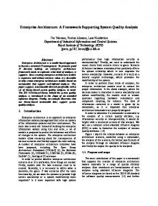
The configuration system we propose consists of two components: a Main Controller and an Addressing and Data Routing Unit (ADRU) (Figure 1). These components are used to organise and distribute the configuration data. The main controller is the interface between the configuration data input port and the ADRU. The configuration port is assumed to be one byte wide like all Virtex devices. The main controller is responsible for the assembly (decompression) of byte sets prior to their distribution to the configuration memory. The main controller also stores configuration parameters and status information. Configuration parameters include F SAi , F SAF and the F SAwe vector, as well
Byte Set Buffer : 30B
Addressing and Data Routing Unit
FSAi /FSAcurrent :1B
Main Controller
FSAF : 1B FSAW E : 4B
Modification Vector : 4B Beneficiary Byte: 1B
0 8
Data Byte
Byte Set : 30B
1
2
3
FSA current
Data Byte
FSAwe [0]
29
C0 0
1
FSA current
Data Byte
FSA we[1]
C29
C1 47
0
1
FSA current
FSA we[29]
47
0
1
47
Configuration Port
Fig. 1. Configuration memory system overview.
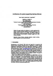
as the modification vector. Status information includes the current frame set address F SAcurrent (the incremented F SAi ), the number of byte sets within the frame set remaining to be prepared (between 0 and 56) and the configuration stage (non-CLB or CLB). The main controller consists of three main sub-components: the status controller, a 30-byte byte set register, and a byte set buffer of equal size. These maintain the status information, the byte set being assembled, and a copy of the previously assembled byte set while it is being broadcast to the configuration memory via the ADRU. In order to assemble a byte set, the beneficiary byte is broadcast to a constant number (8) of byte set registers per cycle while the 4 byte modification vector is being loaded. The controller then loads and routes to the corresponding byte set register entry an additional byte of configuration data for each bit that is set in the modification vector. The overall operation of the main controller is illustrated in the state diagram of Figure 2. The status controller performs the functions described within the unshaded region of the diagram and the byte set register implements the functions within the smaller shaded area. The control and operation of the byte set buffer, not shown in the state diagram, occurs in parallel with the status controller. While the status controller decrements the number of bytes left in the frame set and checks whether it is equal to zero, the previously prepared byte set is transferred from the byte set register to the byte set buffer. While the operation of the main controller continues to prepare the next byte set the byte set buffer is free to transfer the previous byte set to the configuration memory of the device using the ADRU. 4.2
Addressing and Data Routing Unit
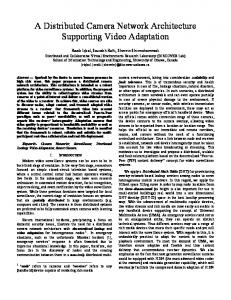
The ADRU is responsible for transferring configuration data from the byte set buffer to the configuration memory elements on the device (Figure 3). Since a byte set can be prepared in as few as 5 cycles, the ADRU must transfer 30 bytes to the configuration memory within this period. In order to minimise the bus
Fig. 2. Main controller state diagram.
width of the ADRU, the proposal envisages transferring 6 bytes per cycle. A 3-bit column group select signal indicates which 6-byte fragment is currently being transferred. When the byte set register unit is accepting the beneficiary byte of the next byte set, the ADRU copies the first 6-byte section of the byte set buffer to the device. The ADRU uses the configuration stage, F SAcurrent and column group select signals to determine how the data is routed to the device. The F SAwe vector selects which bytes are actually written to the device, thus disabling any frame registers not being configured.
5
Analysis of the System
Hardware requirements The hardware requirements of the proposed configuration system are modest and comparable with those currently present in the Virtex family. The main change is to have a somewhat wider data distribution network in the ADRU — up to
6
6
Write Enable (from FSA data) we
FSA current
8
Configuration Data
3
FSA current
Column Group Select 48
Cross device transfer
1 48
ADRU
Byte Set Buffer
Configuration Data
Frame Routing Network Column Data
0
1
2
47
Fig. 3. Address and data routing unit arrangement. Note: just one column is depicted in this diagram.
8 bytes of data in parallel (when fully expanded, as outlined below), compared with 4 bytes — and the ability to shift data into 8 frame registers in parallel (when expanded — for XCV100, 6 frames are targeted). Initial modelling of the area and power needs of our design using Design Compiler from Synopsis suggest power consumption will increase by a factor of about 1.5 over the current Virtex system during configuration, but will be compensated for by having the configuration period reduced by a factor of 2 to 3. This estimate is based on estimates carried out on the system described in [12], which proposes two buses rather than one, and accessed each configuration register twice per cycle in order to be able to modify the configuration currently on chip. The timing of the modification vector update unit was considered to be the critical element within the controller design. This unit employs successive bitclearing logic to route non-beneficiary bytes to the byte set register and to test for the need to load further byte set data. This logic is described by the left pair of states in the shaded region of the state diagram depicted in Figure 2. Our implementation of the successive bit-clearing logic uses a chain of two-input XOR gates, 2 per modification vector bit, and thus has a a delay proportional to the size of the modification vector. With current 90nm process technology, the delay for a 32-bit vector was found to be 1.6ns and is thus insignificant. To gauge the delay of the ADRU we assumed the propagation of data across the device could be supported at the 66MHz configuration clock speed currently used by Virtex. Should this not be possible, the data transfer could easily be pipelined. Benchmark performance In order to evaluate the performance of our proposed configuration system we compared the amount of data currently needed to configure the circuits described
in Section 3 on a Virtex XCV100 with the amount of data needed using our scheme. This data corresponds directly to the number of configuration clock cycles needed to load the configuration bit-stream and to configure the device. Refer to Table 2. The third and fourth column from the right in this table list the total number of bytes, including overheads, that are needed with our proposal and the percentage reduction in bit-stream size. On average, just over 32,000 bytes are needed to configure each circuit while 97,652 bytes are needed using the current XCV100 configuration interface. This is largely due to the way the circuits were mapped, since each required a complete configuration of the device. Primarily this was due to nets crossing the entire device. It would perhaps be more fair to compare the methods when the circuits are compacted into as few columns as possible. Nevertheless, the results are encouraging for most circuits, with an average reduction in configuration bit-stream size and latency of 67.2%. We are concerned that the results for the DCT and IIR circuits indicate less regular, larger circuits will cause significant loss of benefit from compression, particularly as the device utilisation approaches 100%. We are currently investigating this effect with high-stress circuits. Circuit
ammod [4] bfproc [13] ccmul [13] cic3r32 [13] cosine LUT [4] dct [4] ddsynthesiser [13] dfir [4] fir srg [13] iir [13] Average
#LUTs #IOBs #Nets
271 418 262 152 547 1,064 70 179 216 894
45 90 58 42 45 78 44 43 16 62
990 1,347 905 736 2,574 5,327 759 782 726 2,907
Modification Vector Bit-stream Size % Red 28,412 70.9 30,229 69.0 27,179 72.2 26,667 72.7 31,710 67.5 54,315 44.4 25,704 73.7 26,262 73.1 26,143 73.2 42,011 57.0 32,079 67.2
Random Access Bit-stream Size % Red 30,960 68.3 34,140 65.0 28,490 70.8 27,450 71.9 37,580 61.5 71,394 26.9 25,214 74.2 26,668 72.7 26,480 72.9 57,108 41.5 36,548 62.6
Table 2. Bit-stream sizes in bytes (including overheads) and percentage reduction in bit-stream size for benchmark circuits using the proposed scheme (Modification Vector) and an alternative (Random Access).
Random access byte set modification The proposed configuration system has a relatively high fixed overhead of 12,316 bytes for a complete configuration. This overhead, comprising byte set modifi-
cation vectors, frame write masks and frame set ranges, may be too high for partial reconfiguration. To partially configure a single column of the device in which all 48 frames are touched results in 48 frame sets having to be written with an overhead of 10,754 bytes. We therefore examined the performance of an alternative scheme in which non-beneficiary bytes are addressed using a 1-byte address for each byte to be modified in the byte set. This approach should benefit byte sets in which the number of bytes that differ from the broadcast byte is less than four. For the complete configurations under test, we found that this typically led to a net increase in bit-stream size. See the right pair of columns in Table 2. It is expected that this method will have a benefit when the number of non-beneficiary bytes is less than 4 on average. This is more likely for updates covering a small number of columns but will be less likely as the utilisation or the functional density of the frames covered increases. Another factor to be considered with this alternative is that a byte set could be ready for distribution every 2 cycles: just 1 beneficiary byte and 1 end of byte set marker may suffice to specify a complete byte set of 30 bytes. With the XCV100 device, up to 15 frames would therefore need to be configured per cycle in order to maintain the configuration bandwidth at the input port. Scalability The proposed configuration method could be adapted for use in larger devices by repeating and/or expanding the design. The number of frames in each column is fixed for all Virtex series devices, and so need not be considered. Similarly, the number of non-CLB columns in Virtex series devices is fixed. However, there are 96 columns of CLBs in the largest (XCV1000) device, and each frame contains 156 bytes. This represents a significant increase over the XCV100 device in the amount of data to be transferred. The increase in the number of bytes per frame only affects the size of the counter controlling the current byte position, increasing it from 6 bits (56 bytes per frame) to 8 bits (156 bytes per frame). However, the large increase in the number of CLB columns needs further consideration. Repetition refers to adding one CLB configuration stage for each additional set of 32 CLB columns. This strategy necessitates that the controller keep track of the current CLB configuration stage. For example, in the XCV1000 there would be 1 non-CLB stage and 3 CLB stages. The CLB configuration stage is broadcast along with the configuration data in order to configure the correct subset of columns. If necessary, the data bus would be pipelined to cope with delays in broadcasting the configuration and control data across the chip. Expansion refers to the enlargement of existing structures to avoid the use of multiple CLB configuration stages and the need to transfer additional configuration stage data. The Virtex XCV1000 could be implemented using a byte set size of 96. The modification vector system would then have a latency of approximately 96 gate delays. In 90nm process technology this critical path length allows a configuration clock frequency of approximately 200MHz, which at more than twice the speed of current Virtex devices, is adequate.
The broadcast of the beneficiary byte does not pose a problem in an expanded system since at most just 8 bytes must be written to per cycle. The number of bytes needing to be transferred from the byte set buffer to the device would be adapted to 8 bytes/cycle for large devices and therefore does not add prohibitively to the hardware requirements. Accordingly, the number of F SAwe bits needing to be broadcast increases from 6 to 8. Since each of these 8 bytes could be written to any of 12 sets of contiguous columns, the size of the column select group increases to 4 bits. The 200% increase from the XCV100 to the XCV1000 in the number of configuration columns thus necessitates an expansion of the data bus width from 57 to 76 bits. Indeed, if the configuration data is ignored, the overhead in addressing data increases from 9 to just 12 bits. Details on the configuration architecture employed in the latest Virtex-4 series of FPGAs offered by Xilinx are vague. We understand these devices may be thought of as a small, vertically aligned stack of enlarged Virtex-1 devices. The configuration memory is thus partitioned into a small number of wide horizontal bands or pages corresponding to the smaller units comprising the stack, and Virtex-4 frames are partitioned into a small number of sub-units that are individually addressable. We see our approach as being applied at this sub-unit level, with a shared or separate controller for each page of sub-frames.
6
Conclusions and Future Work
This paper has presented an analysis of configurations corresponding to common DSP circuits on a Virtex FPGA. It was found that frames at the same column offsets are likely to contain the same data with one byte occurring with a high frequency at the same byte offset within the frames. A new configuration system was developed to exploit this phenomenon. The architecture simply broadcasts the most frequent byte on selected frames followed by updates to individual bytes where needed. The new design reduced the (re)configuration time for the benchmark set by two-thirds with modest hardware additions. In the future, we would like to extend our method to include configuration caching (studied by many researchers e.g. [7, 16, 6]). We are currently investigating the possibility of caching the update bytes in our method. This is likely to further reduce the (re)configuration time especially for dense circuits. Acknowledgements: National ICT Australia is funded through the Australian Government’s Backing Australia’s Ability initiative, in part through the Australian Research Council.
References 1. A. Dandalis and V. Prasanna. Configuration compression for FPGA-based embedded systems. ACM International Symposium on Field-Programmable Gate Arrays, pages 187–195, 2001.
2. S. Hauck, Z. Li, and E. Schwabe. Configuration compression for the Xilinx XC6200 FPGA. IEEE Transactions on Computer Aided Design on Integrated, Circuits and Systems, Volume 18 Number 8, pages 1237–1248, 1999. 3. M. Huebner, M. Ullmann, F. Weissel, and J. Becker. Real-time configuration code decompression for dynamic FPGA self-reconfiguration. Reconfigurable Architectures Workshop, 2004. 4. ISE Version 5.2. Xilinx Inc., 2002. 5. JBits SDK. Xilinx Inc., 2000. 6. I. Kennedy. Exploiting redundancy to speedup reconfiguration of an FPGA. Field Programmable Logic, pages 262–271, 2003. 7. Z. Li, K. Compton, and S. Hauck. Configuration cache management techniques for FPGAs. IEEE Symposium on Field-Programmable Custom Computing Machines, pages 22–36, 2000. 8. Z. Li and S. Hauck. Configuration compression for Virtex FPGAs. IEEE Symposium on Field-Programmable Custom Computing Machines, pages 2–36, 2001. 9. X. Ling and H. Amano. WASMII: A data driven computer on a virtual hardware. IEEE Symposium on Field-Programmable Custom Computing Machines, pages 33– 42, 1993. 10. W. Luk, N. Shirazi, and P. Cheung. Compilation tools for run-time reconfigurable designs. IEEE Symposium on Field-Programmable Custom Computing Machines, pages 56–65, 1997. 11. U. Malik and O. Diessel. On the placement and granularity of FPGA configurations. International Conference on Field-Programmable Technology, pages 161– 168, 2004. 12. U. Malik and O. Diessel. A configuration memory architecture for fast RunTime-Reconfiguration of FPGAs. International Conference on Field Programmable Logic, 2005. 13. U. Meyer-Baese. Digital signal processing with Field Programmable Gate Arrays. Springer, 2001. 14. J. Pan, T. Mitra, and W. Wong. Configuration bitstream compression for dynamically reconfigurable FPGAs. International Conference on Computer Aided Design, pages 766–773, 2004. 15. A. Ray and P. Athanas. Wormhole run-time reconfiguration. International Symposium on Field-Programmable Gate Arrays, pages 79–85, 1997. 16. S. Sadhir, S. Nath, and S. Goldstein. Configuration caching and swapping. FieldProgrammable Logic and Applications, pages 192–202, 2001. 17. H. Schmit. Incremental reconfiguration for pipelined applications. IEEE Symposium on Field-Programmable Custom Computing Machines, pages 47–55, 1997. 18. S. Trimberger. A Time-Multiplexed FPGA. IEEE Symposium on FPGAProgrammable Custom Computing Machines, pages 22–28, 1997. 19. Virtex 2.5V Field Programmable Gate Arrays Data Sheet, Version 1.3. Xilinx, Inc., 2000. 20. XC6200 Field Programmable Gate Arrays, version 1.10. Xilinx, Inc., 1997.
This article was processed using the LATEX macro package with LLNCS style