IEEE SENSORS JOURNAL, VOL. 11, NO. 2, FEBRUARY 2011
493
A Cross-Layer Scheme for Solving Hidden Device Problem in IEEE 802.15.4 Wireless Sensor Networks Hsueh-Wen Tseng, Shan-Chi Yang, Ping-Cheng Yeh, Member, IEEE, and Ai-Chun Pang, Senior Member, IEEE
Abstract—The IEEE 802.15.4 standard is designed to achieve low-power transmissions in low-rate and short-distance wireless personal area networks (WPANs). For the sake of reducing the control overheads, the modified CSMA/CA protocol used by 802.15.4 does not have the hidden device protection mechanism, such as RTS/CTS mechanism. Previous studies indicated that the probability of any two devices in an infrastructure network unheard of each other is around 41%. Therefore, the hidden device problem (HDP) results in inefficient data transmission and serious power consumption issues in WPAN. In this paper, we propose a cross-layer detection and allocation (CL-DNA) scheme to solve the HDP in IEEE 802.15.4 without the cost of extra control overhead in data transmissions. The proposed scheme detects relationships of hidden devices based on the overlapped signals and then allocates the hidden devices into distinct subperiods for transmissions. Simulation results validated by mathematical analysis show that the proposed scheme significantly improves the goodput with the reduction in power consumption. Index Terms—Hidden device problem, IEEE 802.15.4, medium access control (MAC) protocol, sensor, wireless personal area network (WPAN).
I. INTRODUCTION IRELESS sensor networking (WSN) is one of the most exciting technology today. WSN is expected to be a low-cost and low-power solution for monitoring unsupervised devices in houses, factories and offices. The sensor devices are allocated randomly or artificially to retrieve specific environmental information and then return the results to a gateway via wireless communication. Among the well-known specifications, IEEE 802.15.4, originally designed for low-rate
W
Manuscript received January 17, 2010; revised July 30, 2010; accepted July 31, 2010. Date of publication September 23, 2010; date of current version November 24, 2010. This work was supported in part by the Excellent Research Projects of National Taiwan University under Contract 99R80304, 99R80305 and by the National Science Council under Contract NSC98-2221-E-002-200-MY3, NSC 99-2220-E-002-035. The associate editor coordinating the review of this paper and approving it for publication was Prof. Evgeny Katz. H.-W. Tseng is with the Cloud Computing Center for Mobile Application of Industrial Technology Research Institute, Hsinchu, Taiwan, R.O.C. (e-mail:
[email protected]). S.-C. Yang is with the MediaTek Incorporation, Hsinchu, Taiwan, R.O.C. (e-mail:
[email protected]). P.-C. Yeh is with the Graduate Institute of Communication Engineering, Department of Electrical Engineering, National Taiwan University, Taipei, Taiwan, R.O.C. (e-mail:
[email protected]). A.-C. Pang is with the Graduate Institute of Networking and Multimedia, Department of Computer Science and Information Engineering, National Taiwan University, Taipei, Taiwan, R.O.C. (e-mail:
[email protected]). Color versions of one or more of the figures in this paper are available online at http://ieeexplore.ieee.org. Digital Object Identifier 10.1109/JSEN.2010.2068287
wireless personal area networks (WPANs), has become one of the promising candidates for interconnections between wireless sensor devices. In wireless networks, a device is not guaranteed to hear the signals from other devices. If signals transmitted from device A to device C cannot be sensed by device B, device B thinks that the channel is clear. As a result, device B might transmit data to device C at the same time. The overlapped signals cause the failure of device C to recognize either of the signals sent by device A and B. This is called the hidden device (or hidden terminal) problem (HDP) [9]. In an infrastructure wireless network, assume that the devices have the same transmission radius and are randomly located in the network, the probability of any two devices having a hidden device relationship can be as large 41% [10]. The HDP increases the chance of transmission failures which initiates the retransmission procedures. As a result, the power consumption is high and the battery life of the sensors is shortened. This is a big problem for wireless sensor networks. In IEEE 802.11 standard, the HDP is prevented by the well-known RTS/CTS handshake mechanism. Unfortunately, the IEEE 802.15.4 medium access control (MAC) does not have a protection mechanism against the HDP. A widely studied solution to the HDP is the out-of-band busy tone approach [3], [9]. Receiving devices send out the busy tone signals in a control channel while receiving data packets in a data channel. Any other devices hearing the busy tone will not transmit their own signals. This approach effectively solves the HDP, but it requires an extra channel and an additional transceiver for each device. It also induces extra power consumption which makes it not suitable for IEEE 802.15.4. Several other papers proposed to solve the HDP without the need of additional channels and transceivers [11], [12]. Define the carrier sensing range of a device as the range that the signal transmission from the device can be sensed by any other devices within the range. Note that the signal can be sensed but not necessarily recognizable to the devices in the range. Further define the interference range as the range that the device would fail to detect the received signal if any other devices within the range transmit signals at the same time. Devices can tune the receive power to extend the carrier sensing range. The carrier sensing range is set to be larger than the interference range to resolve the HDP. However, this approach decreases the spatial reuse ratio since a lot of devices outside the interference range of the transmitting device are forced to be silent unnecessarily. Moreover, the HDP cannot be prevented if there are obstructors between the devices.
1530-437X/$26.00 © 2010 IEEE
494
Other than the aforementioned approaches, several papers focused on power control to overcome the HDP [5], [13]. Devices use smaller transmission power which reduces the size of the carrier sensing range and the interference range. As a result, there is less chance for the HDP to happen. However, since the transmission power of IEEE 802.15.4. is already very low, further decreasing the transmission power makes it difficult to maintain reliable communication quality. Therefore, this approach is not applicable to solve the HDP for IEEE 802.15.4. Although ZigZag decoding can combat against the HDP for IEEE 802.11 [2], it does not prevent the occurrence of collision; it is merely a remedy of collision. Its decoding process requires data retransmissions to collide again to recover the collided data. This work is fine in 802.11 since the hidden device issue is not that serious due to the use of RTS/CTS. However, in IEEE 802.15.4, the HDP is much more severe. The prevention of collision is actually more desirable than collision remedy in 802.15.4 since the frequent retransmissions would hurt the battery life of sensors. In addition, ZigZag decoding requires significant amount of buffer on the coordinator device to save the collided signals, and it also needs a lot more processing power on the coordinator device to perform the ZigZag decoding process. The increased hardware complexity and the power consumption are not desired for low power applications such as outdoor sensor networks. Some approaches that target on solving the HDP for IEEE 802.15.4 were proposed in the literatures [6]–[8]. In [6] and [7], all devices are separated into mutually exclusive groups based on their hidden-device relationships. Devices in each group cannot sense each other. Different groups are scheduled to transmit in different time intervals to prevent the HDP. However, in a WSN, the number of devices can be very large and the computation complexity of the approach might be high. The devices may also have moving behaviors. When the network topology changes, the grouping/scheduling procedures need to be conducted again. In [8], the receiver tries to detect two specific fields, frame length and source address, from the corrupted frame to allocate dedicated time/bandwidth to the corresponding devices to freeze the channel contention from these devices. However, these two fields cannot be easily detected from the corrupted frame in the MAC layer due to the severe frame damage resulted from the signal collision in the physical (PHY) layer. In this paper, we propose a cross-layer detection and allocation (CL-DNA) scheme to solve the HDP for IEEE 802.15.4. Upon the occurrence of frame collision, we propose a specially designed algorithm in the PHY layer to estimate the device addresses more accurately from the corrupted frames. The dubious addresses of the device are then verified through a MAC procedure in our design. The verified hidden devices are then scheduled to preserved time slots for transmissions. Our study is one of the very first works that adopt a cross-layer technique to solve the HDP for IEEE 802.15.4. Numerical results obtained by mathematical analysis and simulation experiments show that CL-DNA significantly decreases the chance of the HDP and substantially improves the system performance of IEEE 802.15.4.
IEEE SENSORS JOURNAL, VOL. 11, NO. 2, FEBRUARY 2011
The rest of this paper is organized as follows. An overview of IEEE 802.15.4 is given in Section II. Our CL-DNA scheme is presented in Section III. An analytical model for our CL-DNA is presented in Section IV. The results of extensive numerical experiments are demonstrated in Section V. Finally, the conclusions are given in Section VI. II. IEEE 802.15.4 OVERVIEW This section briefly elaborates on the IEEE 802.15.4 physicallayer and MAC-layer technologies and presents the format of an IEEE 802.15.4 frame. A. Physical Layer The physical (PHY) layer of the IEEE 802.15.4 standard is designed using direct sequence spread spectrum scheme, and supports three different data rates with transmission distance ranging from 10 to 100 meters. The system diagram of IEEE 802.15.4 PHY is defined in [4]. At the transmitter side, data bits are first divided into groups of four bits. Each four-bit sequence is then mapped to one of the sixteen possible symbols and spread to the associated 32-chip sequence. Note that the spread sequences are pseudo-random and nearly orthogonal. The chip stream is offset quadrature phase shift keying (OQPSK) modulated with half-sine pulse-shaping. The modulated signal is transmitted through wireless channel, and the inverse procedures are conducted at the receiver side. The received signal is first demodulated into chips. The 4-bit data symbol is then recovered from the demodulated chip sequence by correlating it to the chip sequence associated to each of the 16 possible symbols and choosing the one with the highest correlation. Finally, the complete bit stream is sent to the MAC layer. Another important feature of IEEE 802.15.4 PHY is the energy detection (ED). ED is generally used to obtain the received signal strength at the receiver. If ED detects a large variation of the received signal strength at the receiver, it is very likely to have been caused by the overlapped signals from the occurrence of the HDP. B. MAC Layer Two network topologies are supported by IEEE 802.15.4 MAC, the star topology and the peer-to-peer topology. In the star topology, each device communicates with others through a coordinator. In the peer-to-peer topology, mobile devices directly communicate with each other. IEEE 802.15.4 MAC specifies two ways of medium access: the beacon-enabled mode and the non-beacon-enabled modes. In the beacon-enabled mode, a beacon frame is transmitted by the coordinator at the beginning of every superframe. The beacon frame contains information about timing synchronization, system configuration, and a list of devices to receive data frames from the coordinator. On the contrary, in the non-beacon-enable mode, devices are allowed to send data packets whenever necessary. In this paper, we consider a beacon-enabled network with star topology, which has high potential for effective design in avoiding the HDP while conforming to the standard. A superframe consists of an active period and an inactive period. Two parameters, beacon order (BO) and superframe order
TSENG et al.: A CROSS-LAYER SCHEME FOR SOLVING HIDDEN DEVICE PROBLEM IN IEEE 802.15.4 WIRELESS SENSOR NETWORKS
495
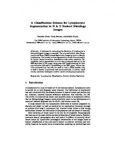
Fig. 1. A CL-DNA illustrative example.
(SO), are set by the coordinator to control the lengths of a active and an inactive periods. The active period is for data transmission/reception, and all the devices sleep in the inactive period for power saving. At the beginning of an active period, a beacon frame is sent from the coordinator to the devices. The active period is divided into two periods, the contention-access period (CAP) and the contention-free period (CFP). To achieve best possible performance, the coordinator adjusts the duration of CAP and CFP based on the traffic load encountered. The channel access in CAP is based on a modified carrier sense multiple access/collision avoidance (CSMA/CA) protocol. The MAC constant a unit backoff period (UBP) is used as a basic unit of the backoff period, which is of length 20 symbols. The symbol period is defined as the transmission time of the aforementioned 4-bit symbol in the PHY layer. Different from the standard CSMA/CA, the devices starts sensing channel only when the backoff countdown process is complete. On the other hand, the CFP slots are reserved by the coordinator for specific devices with real-time applications. The CFP is composed of several guaranteed time slots (GTSs). The coordinator can allocate the GTSs to the devices for data transmissions per the requests. Finally, we note that although it is designed for all devices to sleep during the inactive period in IEEE 802.15.4 for power saving, the standard does not completely rule out the possibility of using the inactive period for data transmissions between selected devices. C. Frame Format IEEE 802.15.4 frame format is defined in [4]. The preamble sequence of the PHY frame consists of four bytes at the beginning of the frame. The content of the preamble is zero padded to 32 bits and is used for synchronization. There are two types of source/destination address, the short address (2 bytes) and the long address (8 bytes). Using the long address allows a large number of devices joining the WPAN, while the short address devices under each coordinator. In this only supports work, we consider only the short address case. Nevertheless, the proposed scheme can be easily extended to the case of the long address. Note that the source address field of the device takes place starting from the 12th byte, i.e., the 23rd 4-bit data symbol, after the preamble in the PHY frame. III. CROSS-LAYER DETECTION AND ALLOCATION SCHEME Here, we propose a cross-layer detection and allocation (CL-DNA) scheme to solve the HDP in IEEE 802.15.4.
CL-DNA consists of operations in both PHY and MAC layers. Upon the occurrence of signal collision, device addresses are detected from the collided signals in the PHY layer to identify the hidden devices. In the MAC layer, the dubious hidden device addresses are double-checked via our HDP address verification procedure. The confirmed addresses of the hidden devices are then added to a hidden device address list (HDAL). A hidden device is scheduled to access the channel by exclusively allocating time slots in different subperiods according to the number of hidden device pairs it belongs to and the size of HDAL, to eliminate its chance of causing the HDP. Detailed description of CL-DNA is given as follows. A. HDP and Address Detection in the PHY Layer As an illustrative example, in Fig. 1, we assume devices A and B are mutually hidden devices. Device B transmits a frame first, and device A later corrupts the frame of device B [Fig. 1(a)]. To detect the occurrence of the HDP, CL-DNA uses the aforementioned ED supported by IEEE 802.15.4 PHY, which monitors the received signal strength at the coordinator. If the HDP occurs, multiple transmission signals overlap. The received signal strength and the ED at the coordinator thus have large variations. Once the HDP is detected, the coordinator then sends a special acknowledgement frame (NACK) [Fig. 1(b)] to notify the possible transmitting devices to stop initiating the retransmission procedure. One flag bit in the ACK frame is used in CL-DNA to distinguish the NACK from the standard ACK. To find out which devices cause the HDP, the coordinator first tries to detect the preamble locations of the collided PHY frames in the overlapped signal and then detects the source address field in the frames using the detected preamble locations. Recall from Section II-C, the preamble sequence of the PHY frame consists of eight continuous data symbols 00000000 (decimal). It is located at the beginning of the PHY frame. The source address field starts from the twenty-third symbol after the end of the preamble sequence. Therefore, the coordinator constantly correlates the chip sequences of the preamble to the received signals. Once the peak correlation value is observed, the coordinator asserts that a preamble sequence is found. When the preamble is detected, the coordinator then compares the received signal portion starting from the twenty-third received data symbol right after the detected preamble, to the chip sequence of each associated source address in its WPAN. The associated source address with chip sequence of the highest correlation to the re-
496
ceived signal portion is considered to be the most probable address of the collided device. B. Time Allocation Algorithm in the MAC Layer Once the HDP addresses are detected, the HDP address verification procedure is initiated by the MAC layer. The procedure is necessary since the newly detected HDP addresses may be in error due to the existing interference and the noise. To verify the detected addresses, the coordinator schedules each dubious hidden device (associated with the detected address) to transmit in the GTS of the following superframe [Fig. 1(c)]. There are two possible cases. One is that the dubious device confirms that the NACK frame received in the previous superframe is associated with its collided frame. Under such circumstance, the dubious device just goes ahead to transmit the frame in GTS. Once the coordinator receives the frame in GTS, it knows that the detected address is correct. On the other hand, if the dubious device does not recognize the NACK frame, it indicates that the device was not involved in the HDP of the previous frame. As a result, the device is forced not to transmit its frame even through it has been scheduled to transmit in GTS. If no frame is received in the allocated GTS, the coordinator concludes that the hidden device address detected by the PHY layer is not correct. The correct hidden device addresses are then added to the HDAL. In order to detect as many existing HDP pairs as possible, the HDAL is stored and getting appended for several superframes before it gets reset. Note that the HDAL reset is necessary since the HDP pair relation between two devices might diminish over time due to the device mobility. The duration between each HDAL pair is defined as a collection period (CP). The length of CP should be determined by the rate of the topology variation of the WPAN. In the beacon following the end of each CP [Fig. 1(d)], the coordinator allocates the hidden devices in the HDAL to different subperiods for transmission to prevent the HDP [Fig. 1(e)]. The HDAL is then reset to start another around of the HDP recording. Recall that there are three types of subperiod: CAP, GTS and the inactive period. The non-hidden devices are allocated in CAP to contend for transmission. The more serious hidden devices, i.e., devices that cause the HDP to larger numbers of devices, are allocated to transmit using GTS to avoid the severe HDP. The remaining hidden devices are allocated in the inactive period, using a special backoff period, which is tripe of UBP (i.e., MAC slot), to access the channel. Using a longer backoff period can decrease the probability of the interference from other hidden devices and thus obtain better channel utilization in the inactive period. One should note that the lengths of the CAP, GTS, and the inactive period should be real-time adjusted according to the number of hidden devices, otherwise there will be a serious fairness problem between the non-hidden devices and the hidden devices. The time allocation algorithm of CL-DNA is performed by and . denotes the exploiting number of devices listed in the HDAL, whereas is the number of devices that device can cause the HDP to. Both can be extracted from the HDAL. In addition, two threshold and , are defined. By values,
IEEE SENSORS JOURNAL, VOL. 11, NO. 2, FEBRUARY 2011
to and to , there are four possible cases. and 1) If , the coordinator infers that the HDP is not severe. The coordinator allocates the hidden devices to transmit in the inactive period. No need to use GTS in this case. and 2) If for some devices, the coordinator concludes that these hidden devices cause more serious HDP. Such devices are allocated to transmit using GTS while the rest of the hidden devices in the HDAL are allocated to the inactive period for transmissions. and 3) If , it indicates that most of the hidden devices are only causing the HDP to a few devices. The coordinator chooses the device with the largest value and allocate it to transmit using GTS. All of the devices in the HDAL with the HDP relation to device are then allocated to the inactive period. Similar procedure is applied to the rest of the hidden devices until the coordinator uses up all the GTSs. The remaining hidden devices are then allocated to the inactive period. and 4) If for some devices, this indicates the HDP problem is severe and device is causing the HDP to many devices. We should allocate at most seven of such values to transmit using devices with largest GTS, while the remaining hidden devices are allocated to transmit in the inactive period. In summary, the CL-DNA scheme resolves the HDP without sacrificing transmission opportunities of non-hidden devices. By judiciously allocating the devices to transmit in different subperiods, the proposed algorithm is able to reduce the chance of the HDP and enhance the goodput, as well as reducing the MAC delay and the power consumption.
comparing
IV. PERFORMANCE ANALYSIS In this section, we propose an analytical model of CL-DNA. The model is assumed to be time slotted, and all time durations are normalized by UBP. We first describe our system model, and then the MAC delay is analyzed. A. System Model A scenario of devices is considered. As shown in Fig. 2, the initial locations of the devices are randomly distributed within a circle with a radius , and the coordinator is located at center of the circle. We assume that the arrival process of frames at a device forms the Poisson distribution with arrival rate . Without loss of generality, the transmission and reception ranges of all devices are assumed to be meters. We that is at a distance of meters to the observe a device value of computed in the coordinator. The pervious CP is used to decide which subperiod (i.e., CAP, GTS, will be allocated for data transmission or inactive periods) is zero, will be allocated in the coming CP. If is larger than in CAP; if
TSENG et al.: A CROSS-LAYER SCHEME FOR SOLVING HIDDEN DEVICE PROBLEM IN IEEE 802.15.4 WIRELESS SENSOR NETWORKS
497
Fig. 2. The scenario for the analytical model.
Fig. 3. The state diagram for CL-DNA.
is allocated to transmit using GTS. Otherwise, is allocated to transmit in the inactive period. if the folA device is considered as the hidden device of lowing two conditions are satisfied: The device is located out of and transmits data in the duration the transmission range of of a transmission frame for . We define as the number of devices that cannot sense the transmission signal of , where the device stays in CAP at the th CP. is defined as the probability that a device transmits at least one frame. At the first CP, and can be expressed as (1)
(2) represents the area of transmission range for . As can be expressed as shown in Fig. 2, . Area denotes the average area of carrier sense for the transmitting device and is equal to . The probability that a device creates at least a data frame to transmit in CP is written as , where is the duration of a superframe. The probability that a device can successfully perform carrier sense is . Initially, all devices are allocated in CAP to transmit their data. We use the Poisson distribution with a mean of to approximate the distribution of of . With this approximation, , and can be obtained. Let be the transition probability from “Origin” state to “Target” state in the th CP. is the probability that transmits a data frame in CAP during the first CP and it stays on in CAP during the second CP because is equal to zero. The definitions of and are similar to . Fig. 3 shows
is allocated in CAP, the the transition diagram. When can be expressed as
(3) As is scheduled in CAP, there are other devices also scheduled in this period, and we define the number of these . can be comdevices as puted as follows. The first part includes the devices within that do not transmit data frame in the previous CP, and the number of such the devices can be expressed as . The other part that transmits data frame and includes the devices within of these devices is equal to zero in the previous CP. Thus, can be expressed as
Therefore, the number of devices that cannot sense the when is allocated in CAP, transmission signal of , can be written as
(4)
498
When
IEEE SENSORS JOURNAL, VOL. 11, NO. 2, FEBRUARY 2011
, the
is written as
(5)
is scheduled in the inactive period, some devices When are also scheduled in the inactive period. These devices are out and have of for . can be expressed as
is defined as the probability that a device transmits at least one frame in inactive period, and it is expressed as
We describe
and can be expressed as
(6)
(12)
as follows. The
is defined as the number of devices that cannot when is allocated in sense the transmission signal of inactive period. Thus, it is expressed as
(13) is allocated in inactive period, we still use of in the pervious CP to allocate to different subperiods in the current CP. The , can be expressed as When the
(7)
(14) and Let and and can be expressed as
can be expressed as
denote . The
(8) Note that a maximum of seven devices can be allocated in GTS so that a device is allocated in GTS when and the number of devices in GTS are smaller than seven. Thus, can be expressed as (9)
(15) (16) Let and
and
denote , where
is equal to
When transmits frame in CAP, the frame can be collided or interfered by its hidden deby other devices within vices. Therefore, we define as the probability that the frame of is transmitted without collision in CAP and as the probability that transmits a frame in CAP but the frame is interfered by other hidden devices, and they are expressed as
when is larger than or equal to 2. transmits a frame in the inactive period, the frame When can be collided by other devices within or interfered by its hidden devices. Therefore, we define as the probais transmitted without collision in the bility that the frame of inactive period and as the probability that transmits a frame in the inactive period but the frame is interfered by other hidden devices. They are expressed as
(10)
(17)
(11)
(18)
TSENG et al.: A CROSS-LAYER SCHEME FOR SOLVING HIDDEN DEVICE PROBLEM IN IEEE 802.15.4 WIRELESS SENSOR NETWORKS
499
Fig. 4. The state transition diagram for CL-DNA.
B. MAC Delay Analysis Fig. 4 illustrates the state transition diagram of a device during a specific subperiod. The diagram consists of five states: , and GTS. IDLE, ARRIVE, From Section IV-A, we obtain a probability that a device stay in a subperiod to transmit data and then use the state transition diagram to analyze the average MAC delay of the device for CL-DNA. The MAC delay is defined as the interval between the time that the device serves a frame and the time that the frame is successfully transmitted. The delay analysis is composed of the following three parts. 1) Average MAC Delay in CAP: We observe the device . Initially, stays in IDLE state. When a data frame arrives, the state transits from IDLE state to the ARRIVE state. In ARRIVE state, the arrival frame is queued in the buffer of . will be allocated in different subperiods according to the value of . If of is zero, is scheduled in CAP. When the frame is served by , the channel sensing procedure is executed. The state transits from ARRIVE state to state. The average waiting time in state for in the th CP is , and the is given by
transmission time when a transmitting frame is interfered by and are equal to other hidden devices. and , where and , respectively, denote the transmission times for a data is a gap between the data frame frame and a ACK frame. and the ACK frame. Let denote the size of contention window (CW) for a frame transmission in the th backoff retry, and the basic CW unit is UBP. By following the IEEE 802.15.4 specification, at most three times of retry are allowed for a frame. Thus, the CW size of the th retry will be for 1, 2, and 3, where . Let and represent the average time durations of a successful and a failed channel accesses in the th/ th retry, respectively. In IEEE 802.15.4, a successful channel access implies two times of successful CCA operations. If one of the CCAs is not successfully executed, it is considered that the channel access for this frame transmission fails. Thus, we have and . The average time that transmits a data frame successfully can be expressed as
The average time that transmits data unsuccessfully due to collisions can be expressed as . The average time that transmits data unsuccessfully due to HDP will be (19)
Let and denote, respectively, the average transmission time when a frame is successfully transmitted and the average
500
IEEE SENSORS JOURNAL, VOL. 11, NO. 2, FEBRUARY 2011
The delay time for the HDP address verification procedure of a , where is the device is duration of a active period. In IEEE 802.15.4, when a device executes backoff countdown and the remaining UBPs of CAP is shorter than data length, this data frame will suspend its transmission and then wait for be the probability next CAP to transmit data. Let that the above situation occurs. can be expressed as . In addition, if a device is allocated in CAP to transmit data frame, and the data frame is created by the device in GTS or inactive period, this data frame will wait for next CAP for transis the probability that the above situation mission. , occurs, which is expressed as where and are the durations of a GTS and a inactive is defined as the average periods, respectively. attempts to access backoff interval from the time that actually transthe channel for a frame to the time that mits the frame over the channel, and it can be expressed as where . Thus, the MAC delay of CAP, can be obtained
, the probability that inactive period for transmission. the above situation occurs, can be expressed as . The average backoff interval for the inactive period is denoted , and can be expressed as as , where . and represent the average time durations of a successful and a failed channel accesses in the th/ th retry, respectively. Note that and are different from and because the unit of backoff used in the inactive period is a special backoff period instead of UBP. Therefore, the MAC delay of the inactive period, , can be expressed as
, (22)
(20) 2) Average MAC Delay in Inactive Period: If of is less than will be allocated in the inactive period. If attempts to transmit data, the state transtate. The average sits from ARRIVE state to waiting time in the state for is . It is similar to (19) and given by
3) Average MAC Delay in GTS: If of is larger than , the state transits from the ARRIVE state to the GTS state. The average waiting and given by time in the GTS state is equal to . The expected waiting time when this frame is created in CAP or inactive period is . The MAC delay of GTS is expressed as . is defined as the probability that a device transmits at least one . frame in GTS, and is expressed as Thus, the average MAC delay of , can be obtained . By integrating , we obtain the average MAC delay for all devices for CL-DNA, and it is derived as . Our analytical model has been validated against the simulation experiments. Fig. 5 shows the average MAC delay obtained from analysis and simulation for CL-DNA, where CP, SO, BO, and are assumed to be ten superframes, 2, 3, and 2. From this figure, we observe that the curve of analytical results is quite close to that of simulation. However, the analytical and simulation results do not match very well since of devices in the analytical model is approximated by a Poisson distribution instead of a real trace. V. NUMERICAL EXPERIMENTS
(21) is similar to
, and can be written as . If a device is allocated in the inactive period to transmit data frame, and the data frame is created by the device in CAP or GTS, this data frame will wait for next
A. Simulation Model This section is to evaluate the performance of the proposed CL-DNA scheme. The current discrete-event network simulators such as OPNET, NS-2, J-Sim, and GloMoSim may be unsuitable to implement a cross-layer solution, since their inner structure is based on a layering design, and each implemented
TSENG et al.: A CROSS-LAYER SCHEME FOR SOLVING HIDDEN DEVICE PROBLEM IN IEEE 802.15.4 WIRELESS SENSOR NETWORKS
501
Fig. 6. Probability of address detection. Fig. 5. Comparison of the analysis and simulation results.
Size
functionality run by the simulator engine is tightly coupled with this structure. Hence, implementing a cross-layer solution in one of these simulators may turn into a non-trivial task. For this reason, we develop a simulator ourselves, and the simulator can be used to easily incorporate cross-layer algorithms and protocols. In the physical layer of our simulation environment, Rayleigh fading environment is adopted to cope with realistic channel condition. For the MAC layer, the simulator follows the specification of IEEE 802.15.4 [4]. To clearly indicate the power saving features of the proposed scheme, a transceiver Chipcon CC2420 model [1] is adopted. The length of data frames is assumed to be exponentially distributed with a mean of UBP. Only uplink traffic is considered in our simulation since all data frames in sensor networks are transmitted to the sink device. Also, a beacon-enabled network with a star topology is considered. The coordinator is static and located at the center of simulated area. The proposed scheme can easily be extended to accommodate other network configurations. In our simulation model, the transmission range of all devices is assumed to be 25 m with a transmission rate of 250 Kb/s. We simulate a scenario of 50 devices and their initial locations m . The are randomly distributed within a circle area of moving direction of each device is randomly selected. When the boundary is reached, the device re-selects a direction, and moves toward the direction as described above. The moving speed of the device is randomly selected from 0 to 1 m/s. Each device maintains a FIFO waiting buffer of infinite frames, and the mean frame length, i.e., , is assumed to be 60 bytes (e.g., six UBPs at the 250-Kb/s transmission rate, excluding PHY and MAC . The is Poisson headers). The traffic load is defined as packet arrival rate of a device and is the number of devices. In addition, we assume the links of different devices to the coordinator is independently Rayleigh distributed and the noise at the coordinator is additive white Gaussian noise. Each device estimates the channel gain of its link to the coordinator from the received signal portion of the preamble sequence. The channel
TABLE I
AND
Severeness
SETTINGS FOR 30 DEVICES
estimation is then applied in the PHY to detect the remaining data contained in the PHY frame. B. Address Detection Here, we show the simulation result of address detection introduced in Section III-A. The simulation result under Rayleigh fading is given in Fig. 6. Note that denotes the probability that device addresses are correctly detected given that frames collide to each other, and . In Fig. 6(a), we can observe that the probability of both addresses correctly detected is around 0.65 in the case of 2-frame collision. In Fig. 6(b), the probability of two or more addresses correctly detected (sum of the top two curves) is over 0.82 in the case of 3-frame collision. It is worth noted that, while the probability of correctly detecting 2 or more addresses in a HDP is not extremely close to 1, numerical results in the next subsection shows that such address detection accuracy is sufficient enough to have impact on the system throughput using our HDP resolving MAC design. C. CL-DNA Performance In order to investigate the performance of CL-DNA, we use five representative settings for and from 30 and 50 device as shown in Tables I and II. The mean value, maximum value, and minimum value of and are used in our simulation in different the number of devices. We observe the and from 30 mean value of and 50 devices. The mean values are 20/20 and 3/2 for 30 and
502
IEEE SENSORS JOURNAL, VOL. 11, NO. 2, FEBRUARY 2011
Fig. 7. Effects of traffic load on system goodput, power consumption and MAC delay.
Size
TABLE II
AND
Severeness
SETTINGS FOR 50 DEVICES
50 devices. In general, the mean value of should be increased but the mean value of for 50 devices is less than that of 30 devices due to many signals overlapped so the exact number of devices does not be recognized by coordinator. First, we compare the different performance metrics for CL-DNA and IEEE 802.15.4 standard with 50 devices, and Fig. 7(a) shows the effect of the traffic load on goodput. The numeral footnote of CL-DNA indicates the setting of and listed in Table I. We observe that the goodput of CL-DNA outperforms IEEE 802.15.4 standard. The probability of HDP is decreased by CL-DNA because the hidden devices are properly separated into suitable subperiods. Hence, CL-DNA substantially decreases collision overhead and increases goodput. Furthermore, the performance difference between CL-DNA and IEEE 802.15.4 standard gradually increases when the traffic load increases. The reason is that when traffic load is high, HDP becomes more serious in IEEE 802.15.4. Fig. 7(b) shows the effect of traffic load on power consumption for CL-DNA and IEEE 802.15.4 standard. In wireless sensor networks, power consumption is a major issue. Power consumption for both CL-DNA and IEEE 802.15.4 standard increases as the traffic load increases. However, with
the effective reduction of HDP, the increasing rate of CL-DNA power consumption is less than IEEE 802.15.4 standard. Fig. 7(c) shows the MAC delay of CL-DNA and IEEE 802.15.4 standard. This figure intuitively shows that the MAC delay under CL-DNA and IEEE 802.15.4 standard increases as traffic load increases. We find the MAC delay of IEEE 802.15.4 is lower than that of CL-DNA. In IEEE 802.15.4, more retransmission process for a specific frame may be repeatedly activated due to severe HDP. Each retransmission incurs additional contention overheads and degrades system performance. In CL-DNA, a fame can be successfully delivered with a low HDP opportunity, which implicitly decreases the contention/collision overhead for a frame transmission. Although CL-DNA can significantly reduce the occurrence of HDP, the MAC delay would be increased since some of the devices are arranged to GTS and inactive period. In addition, more hidden devices in the inactive period result in larger contention overheads and thus larger MAC delay. Fig. 8 demonstrates the experimental results for the effect of number of devices on CL-DNA performance, where and of Table I are used. From Fig. 8(a), we observe that the goodput of setting 2 and setting 4 are better than that of other settings for 30 and 70 devices. On the other hand, the goodput of setting 5 and setting 1 exhibit serious degradation for 30 and 70 devices. For a 70-device scenario, the GTSs are totally used easy because of using smaller setting so CAP is shorter. The non-hidden devices produce serious collision overheads due to the small CAP. This implies that and shall be increased to obtain better performance as the number of devices increases. The power consumption affected by the number of
TSENG et al.: A CROSS-LAYER SCHEME FOR SOLVING HIDDEN DEVICE PROBLEM IN IEEE 802.15.4 WIRELESS SENSOR NETWORKS
503
Fig. 8. Effects of number of devices on system goodput, power consumption and MAC delay.
devices for CL-DNA is shown in Fig. 8(b). An intuitive result is observed that the power consumption of CL-DNA increases as the number of devices increases. The power consumption of setting 5 and 1 are slightly higher than that other setting for 30 and 70 devices. In order to separate hidden devices into GTS and inactive period appropriately, the settings of and should be increased when the number of devices is large. Fig. 8(c) shows the MAC delay of CL-DNA. Contrary to power consumption, the MAC delay of setting 1 is greater than that of other settings for 30 and 70 devices, and their difference increases significantly as the number of devices and increases. That is, small values could not effectively solve excessive HDP. However, and should be increased the following the number of devices to separate the hidden devices into suitable subperiods, effectively. VI. CONCLUSION A simple and efficient cross-layer scheme, CL-DNA, has been proposed in this paper to solve the HDP in IEEE 802.15.4 WPANs. The proposed scheme detects the hidden devices addresses based on the overlapped signals in the PHY layer, and the dubious addresses are checked by the HDP address verification procedure performed in the MAC layer. The verified hidden devices are then allocated to different subperiods for transmissions. The proposed cross-layer scheme significantly reduces the chance of hidden device problem. Simulation results show that the proposed CL-DNA is very effective in enhancing the goodput, as well as reducing the MAC delay and the power consumption. Therefore, CL-DNA is a simple and
efficient approach for enhancing IEEE 802.15.4 protocol in wireless sensor networks. REFERENCES [1] Data Sheet for CC2420 2.4 GHz IEEE 802.15.4/Zigbee RF Transceiver [Online]. Available: http://focus.ti.com/docs/toolsw/folders/ print/cc2430dk.html [2] S. Gollakota and D. Katabi, “Zigzag decoding: Combating hidden terminals in wireless networks,” in Proc. ACM SIGCOMM, 2008, pp. 159–170. [3] Z. J. Haas and J. Deng, “Dual busy tone multiple access (DBTMA)—A multiple access control scheme for ad hoc networks,” IEEE Trans. Commun., vol. 50, no. 6, pp. 975–985, Jun. 2002. [4] IEEE 802.15 Working Group, “Standard for Part 15.4: Wireless Medium Access Control Layer (MAC) and Physical Layer (PHY) Specifications for Low Rate Wireless Personal Area Networks (LR-WPANs),” IEEE Std. 802.15.4, Oct. 2003. [5] E. S. Jung and N. H. Vaidya, “A power control MAC protocol for ad hoc networks,” in Proc. ACM Int. Conf. Mobile Computing Networking (MOBICOM), 2002, pp. 36–47. [6] A. Koubaa, R. Severino, M. Alves, and E. Tovar, “Improving quality-of-service in wireless sensor networks by mitigating hidden-node collisions,” IEEE Trans. Ind. Informat. (Special Issue on Real-Time and Embedded Networked Systems), vol. 5, no. 3, pp. 299–313, Aug. 2009. [7] L.-J. Hwang, S.-T. Sheu, Y.-Y. Shih, and Y.-C. Cheng, “Grouping strategy for solving hidden-node problem in IEEE 802.15.4 LRWPANs,” in Proc. IEEE WICON, Jul. 2005, pp. 26–32. [8] S.-T. Sheu, Y.-Y. Shih, and W.-T. Lee, “CSMA/CF protocol for IEEE 802.15.4 WPANs,” IEEE Trans. Veh. Technol., vol. 58, no. 3, pp. 1501–1516, Mar. 2009. [9] F. A. Tobagi and L. Kleinrock, “Packet switching in radio channels: Part II—The hidden terminal problem in carrier sense multiple-access and the busy-tone solution,” IEEE Trans. Commun., vol. 23, no. 12, pp. 1417–1433, Dec. 1975. [10] Y.-C. Tseng, S.-Y. Ni, and E.-Y. Shih, “Adaptive approaches to relieving broadcast storms in a wireless multihop mobile Ad Hoc network,” IEEE Trans. Comput., vol. 52, no. 5, pp. 545–557, May 2003.
504
IEEE SENSORS JOURNAL, VOL. 11, NO. 2, FEBRUARY 2011
[11] X. Yang and N. H. Vaidya, “On the physical carrier sense in wireless ad hoc networks,” Proc. IEEE Infocom, pp. 2525–2535, Mar. 2005. [12] H. Zhai and Y. Fang, “Physical carrier sensing and spatial reuse in multirate and multihop wireless ad hoc networks,” Proc. IEEE Infocom, pp. 1–12, Apr. 2006. [13] J. Zhu, X. Guo, L. L. Yang, and W. Steven, “A single-channel solution for transmission power control in wireless ad hoc networks,” in Proc. ACM Int. Symp. Mobile Ad Hoc Networking Computing (MOBIHOC), 2004, pp. 210–221. Hsueh-Wen Tseng received the B.S. degree in electrical engineering from Tamkang University, Taipei, Taiwan, in 2001, the M.S. degree in electrical engineering from the National Taiwan University of Science and Technology, Taipei, Taiwan, in 2003, and Ph.D. degrees from the Department of Computer Science and Information Engineering, National Taiwan University, Taipei, Taiwan, in 2009. He is currently an Engineer in the Cloud Computing Center for Mobile Application of the Industrial Technology Research Institute, Hsinchu, Taiwan. His research interests include networked embedded system, cloud computing, design, analysis and implementation of network protocols and wireless communications.
Shan-Chi Yang received the B.S. degree in electrical engineering from the National Taiwan University, Taipei, Taiwan, in 2007 and the M.S. degree from the Graduate Institute of Communication Engineering at the National Taiwan University, Taipei, Taiwan, in 2009. He is currently an Engineer in the MediaTek Incorporation, Hsinchu, Taiwan. His research interests include analysis and implementation of network protocols in wireless communications.
Ping-Cheng Yeh (M’05) received the B.S. degree in mathematics and the M.S. degree in electrical engineering from the National Taiwan University, Taiwan, in 1996 and 1998, respectively, and the Ph.D. degree from the University of Michigan, Ann Arbor, in 2005. He is currently an Assistant Professor in the Graduate Institute of Communication Engineering, and the Department of Electrical Engineering at the National Taiwan University. His research interests include channel coding, coded modulation, directional antennas, cooperative communications, and cross-layer design in wireless networks.
Ai-Chun Pang (S’00–M’02–SM’09) received the B.S., M.S., and Ph.D. degrees in computer science and information engineering from the National Chiao Tung University, Taiwan, in 1996, 1998, and 2002, respectively. She joined the Department of Computer Science and Information Engineering (CSIE), National Taiwan University (NTU), Taipei, Taiwan, in 2002. Currently, she is an Associate Professor in CSIE and the Graduate Institute of Networking and Multimedia of NTU, Taipei, Taiwan. Her research interests include design and analysis of personal communications services network, mobile computing, voice over IP, and performance modeling.