Abstract. This paper presents a custom processor designed to execute a time consuming function in a CFD application. The selected function implements the.
A Custom Processor for a TDMA Solver in a CFD Application⋆ Filipe Oliveira1 , C. Silva Santos3 , F. A. Castro3 , and José C. Alves1,2 1
Instituto de Engenharia de Sistemas e Computadores do Porto (INESC-Porto) 2 Faculdade de Engenharia da Universidade do Porto (FEUP) 3 Centro de Estudos de Energia Eólica e Escoamentos Atmosféricos (CEsA)
Abstract. This paper presents a custom processor designed to execute a time consuming function in a CFD application. The selected function implements the method TDMA (Tri-Diagonal Matrix Algorithm) for solving a tri-diagonal system of equations. The custom processor was implemented in a commercial PCI prototyping board based on Virtex4LX FPGAs and uses a dedicated memory cache system, address generators and a deep pipelined floating-point datapath. Running at 100MHz and assuming the input data already in the cache memories, the system reaches a throughput greater than 1.4GFLOPS.
1 Introduction Computational Fluid Dynamics (CFD) are numeric intensive computer applications to simulate the behavior of a fluid flow over a given physical domain, under certain initial and boundary conditions. The CFD application addressed in this work is the simulation of wind flow over complex terrain. In this class of applications, a CFD simulation is carried out over a 3D rectangular volume corresponding to the location under study, that is divided into a 3D mesh with a variable grid size. Final results of a simulation are the physical properties of the air flow at each point in that mesh like the 3 orthogonal components of wind speed, pressure and kinetic energy of the air. These values allow to construct a 3D map of the wind flow in the domain under study at a given point in time (stationary simulations) or to evaluate the steady state behavior of these variables over time, at a selected point in the simulation domain (transient simulations). These simulations are performed by numeric iterative processes well known by the scientific community, for which stable resolution methods exist. These techniques rely on solving numerically a set of partial differential equations that describe the physical relationship among the variables at each grid node and its neighbors (the Navier-Stokes equations) as an approximation by finite-difference equations. In the work addressed in this paper, a function was selected from a FORTRAN software code [1], [2], [4] that uses the method SIMPLE, (Semi-Implicit Method for Pressure-Linked Equation) [5] to model the Navier-Stokes equations and the TDMA algorithm to solve the system of equations. Duration of simulations, performed by desktop computers, may range from hours to days, depending on the number of points of the 3D grid that represent the domain ⋆
This work is funded by FCT (Fundação para a Ciência e Tecnologia), project POSC/EEAESE/58513/2004
under simulation and the speed of convergence of the iterative process (this if affected, for example, by the complexity of the terrain that may slow the convergence process). This way, even a modest speedup in the computation process may represent a significant amount of absolute time saved to run a simulation. Preliminary profiling of the original software code has shown that approximately 60% of the overall execution time is spent in a very regular sequence of computations that implement the method TDMA (from now we will refer to this function as ’solver’). This routine is formed by a set of 6 similar FOR loops, where the inner computations share the same structure and use only elementar arithmetic operations performed on single precision floating-point data. This regularity and the high cost of the execution of this small code in the overall program has selected this as the first candidate for migration to a custom processor. Measuring the real CPU time taken by this section of code and counting the number of elmentar floating point operations executed has shown an average performance around 100MFlops, for a typical sized problem (121x36x62 nodes). With appropriate pipelined datapaths, control and memory strutctures this value can be easily overtaken by current FPGA technology, thus the motivation for this development. Little previous work has been found on FPGA-based acceleration applied to this class of problems. A first proposal for a custom computer for CFD applications was the DREAM-1 and DREAM-1A machines [6]. The authors propose a parallel processing system made of vector processing nodes and local memory partially implemented by hard disks. By this time, FPGA technology had no capacity for such applications and the hardware system was built with discrete chips. In [7] a custom processing architecture is proposed for CFD computations, targeted to the BenNUEY card and BenDATA modules [8]. The authors propose a computing architecture tailored for that hardware platform, using massive parallel memory access and mapping each arithmetic operation in the software code to a floating-point hardware operator in the computation pipelines. Actual datapath architecture and implementation data is presented for only a specific function and performance results presented are based on projections for some of the most computing intensive functions. However, some critical aspects are not addressed, like the operation scheduling and techniques to overcame the data dependencies that otherwise will stall the pipelines. This paper presents the implementation of a FPGA-based custom processor for acceleration of the most time consuming function in a CFD application. The rest of the paper is organized as follow. Section 2 presents the function targeted in this work. Section 3 addresses the high-level transformations that were exploited to resolve data dependencies and maximize the pipeline efficiency. Section 4 presents the reconfigurable hardware platform that is being used in this work. In section 5, the organization of the custom processor is presented, including the cache memory subsystem and computation datapath. Closing the paper, section 6 shows preliminary results and draw the final conclusions.
2 CFD - the problem The CFD application addressed in the work was derived from a FORTRAN software code to simulate the wind flow over complex terrain. The TDMA solver selected to be
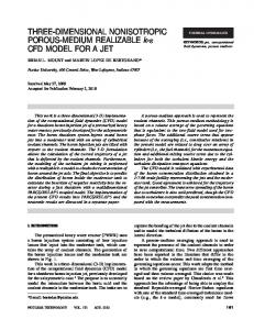
implemented in the custom computing platform has a very regular structure with various nested FOR loops and performs a set of arithmetic operations on single-precision floating-point matrices. Current FPGA technology can easily surpass the 100MFLOPS performance measured for a typical sized simulation running on a 3.2GHz PC, through custom design of the datapath, controlpath and, in particular, the memory subsystem. Figure 1 shows the structure of the function ’solver’. The input variables are 8 threedimensional matrices representing the coefficients of the system of equations being solved, plus another three-dimensional matrix (phi()) containing the data that represents the current solution. The output results of this computation are placed in the matrix phi(). In each iteration, this function is called with a set of different coefficients computed by other sections of the program that were not addressed in this work. for n=1 to nsweep for k=kmin to nk a(jminm1)=0 for i=imin to ni c(jminm1)=phi(i,jminm1,k) for j=jmin to nj a(j) = an(i,j,k) forward b(j) = as(i,j,k) loop c(j) = ae(i,j,k) * phi(i+1,j,k) + aw(i,j,k) * phi(i-1,j,k) + at(i,j,k) * phi(i,j,k+1) + ab(i,j,k) * phi(i,j,k-1) + su(i,j,k) d(j) = ap(i,j,k) term = 1 / ( d(j) - b(j) * a(j-1) ) a(j) = a(j) * term c(j) = ( c(j) + b(j) * c(j-1) ) * term
backward for j=nj to jmin step -1 phi(i,j,k) = a(j) * phi(i,j+1,k) + c(j) loop
Fig. 1. The pseudo-code illustrating the structure of one of the six blocks in function ’solver’. The other 5 blocks are similar to this by permuting the i, j and k control variables of the three nested FOR loops.
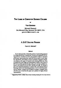
The sequence of operations shown in figure 1 can be divided into 2 sections: forward loop and backward loop. The forward loop produces as output the vectors c(j) and a(j), executing 8 multiplications, one division and 6 additions/subtractions in each loop iteration (for each j). The backward loop uses these two vectors to compute the final elements of the output matrix phi(i,j,k), along the dimension j; this section performs one more multiplication and one addition. A straightforward mapping of the dataflow graph of each section into an arithmetic datapath can be obtained easily, as shown in figure 2. In spite of the simple structure of these circuits, there are two problems that must be solved in order to exploit efficiently the low level parallelism afforded by these datapaths, considering their implementations as a network of pipelined floating-point operators. One is the (relatively) large number of operands required for the forward datapath. To maximize the efficiency of the pipeline, the 15 operands must be issued at the pipeline clock rate, what requires a convenient organization of the memory system and dedicated address generators. The other problem is the data dependencies that exist in
c(j-1) as(i,j,k)
*
phi(i+1,j,k) ae(i,j,k)
*
+
phi(i-1,j,k) aw(i,j,k)
*
+ +
phi(i,j,k+1) at(i,j,k)
*
+
phi(i,j,k-1) ab(i,j,k)
+
*
*
c(j)
*
a(j)
su(i,j,k) 1 ap(i,j,k)
-
as(i,j,k) a(j-1)
:
*
an(i,j,k)
forward loop
c(j)
+
phi(i,j+1,k) a(j)
phi(i,j,k)
* backward loop
Fig. 2. The datapath that implements the core operations of the forward loop and the backward loop.
the forward loop: to start the computation of one instance of c(j) and a(j) the previously computed values for c(j-1) and a(j-1) must be ready at the pipeline inputs. This means it will not be worth to schedule the computations through the pipeline in the same sequence represented by the original code, because that would require an issue rate for the input data equal to the pipeline latency. On the other hand, if the scheduling of the computations do not follow the same order as in the original code, the final numerical results may alter in some way the overall output of the iterative process.
3 High-level transformations Analyzing the figures 1 and 2, the inner computation in both loops is performed along index j, for a fixed k and i (note the outer loop is just a repetition nsweep times of the whole process). Assuming a pipeline with N stages and considering the original scheduling, the input dataset for index j+1 could only be issued to the pipeline inputs N clock cycles after the input dataset for index j, thus leaving N − 1 empty slots in the pipeline. Besides, in the original code, the calculation of each c(j) uses the most recent values of phi(i±1,j,k±1). According to the iteration order, the loops along
j (inner loop) for a given i and k will always use the results of phi(i-1,j,k-1) already computed for the previous values of i and k (i − 1 and k − 1, respectively). To fully utilize the pipeline slots, the solution adopted was to dispatch into the computation pipeline (forward loop) a sequence of input data for the same j (inner loop) but for k and i (the two outer loops) addressing the elements of the (i,k) plane in a checkerboard fashion: first, compute all the elements along j on the “black” cells and then on the “white” cells. Considering a pipeline with N pipestages, the computations corresponding to the loop instance (i,j + 1,k) may be started N clock cycles after the instance (i,j,k). This is when the c(j) and a(j) values required to start iteration (i,j + 1,k) are ready at the pipeline outputs and may be feed back to the datapath inputs. This is functionally equivalent to the pseudo-code shown in figure 3. for n = 1 to nsweep*2 for k = kmin to nk a(jminm1) = 0 k1 = k - kmin + (n-1)%2 for i = imin + k1%2 to ni step 2 c(jminm1) = phi(i,jminm1,k) for j = jmin to nj a(j) = an(i,j,k) ... c(j) = ( c(j) + b(j) * c(j-1) ) * term for j = nj to jmin step -1 phi(i,j,k) = a(j) * phi(i,j+1,k) + c(j)
forward loop backward loop
Fig. 3. The modified pseudo-code of the main loop in function ’solver’, modified to reflect the scheduling implemented by the hardware system.
To verify the feasibility of the application of this process, in terms of the numeric results obtained for a real CFD simulation, the original FORTRAN code of function ’solver’ was modified to execute in the same fashion depicted in figure 3. The execution of a few typical CFD simulations using this new arrangement of the function ’solver’ has shown surprisingly good results. All the runs experimented have reached the convergence criteria of the iterative process not slower than the original code. In one case, the solution has even converged after running only 50% of the number of iterations required by the original program. Besides, the final simulation results that represent the physical parameters of the simulated wind flow differ from the “golden” results by differences that, in terms of their physical meaning, can be considered negligible. Although these results cannot formally prove the validity of the method for all the cases, we can affirm with an high degree of confidence that the same behavior will certainly be observed in simulations with similar characteristics. 3.1
Example of scheduling
This strategy is exemplified in figure 4, assuming a datapath with 8 pipeline stages and issue rate equal to 1 clock cycle. For a matter of clarity, we will call j-column(i,k) to the vector formed by all the elements of a matrix along the dimension j, for a given (i,k); a
black j-column starts in a black cell of the checkerboard and a white j-column starts in a white cell. First iteration (stage 1) starts with (i,j,k)=(0,0,0); next dataset sent to the pipeline inputs is the position (i,j,k)=(2,0,0), then (4,0,0) and so on, until the results of the first input data are present at the output of the pipeline, 8 clocks later (the schedule order of the first elements in each j-column is represented by the numbers 1 to 8 in the black cells of the checkerboard in figure 4).
second block of 8 j-columns
i
129
72
k 67
3
2
66
65
8
7
6
71
70
69
68
values of phi() needed to compute this result
131
130
4
5
1 j-column(1,3) j first block of 8 j-columns
schedule order for the first elements in the (i,k) plane (j=0) of the first j-column block 9 17 25 33 41 49 57
i=0, k=0
1
i=3, k=1
7 15 23 31 39 47 55 63 j schedule order along a j-column
Fig. 4. Scheduling the operations through the forward loop pipeline.
At this point (stage 9), these results are re-injected in the pipeline inputs c(j-1) and a(j-1) to execute the iteration j + 1: (i,j,k)=(0,1,0), then (2,1,0), (4,1,0) and so on. Sixty-four clock cycles after the first dataset was sent to the pipeline inputs, the computation of the first block of 8 j-columns (dot-dot contour) is complete and the results stored in 8 vectors c(j) and a(j). This happens at stage (clock cycle) 65, when the computation of a new block composed by the next 8 black j-columns can start (dash-dash contour). At the same time, the backward loop is executed along the freshly computed j-columns, using a similar scheduling mechanism to compute the final phi() values for the matrix positions corresponding to the black j-columns.
Note the value of the results computed during the forward loop (the vectors c(j) and a(j)) only use the phi() values of the neighbor nodes corresponding to the original input data. Thus, there are no data dependencies among the calculation of the results for each j-column. When the first outer loop iteration is concluded (corresponding to n = 1 in the code of figure 3, the matrix phi() has newly computed values in the positions corresponding to the black j-columns, and the original input values in the positions of white j-columns. The second iteration along i repeats the process described above for the white j-columns. During this phase, the computation of each element of the vectors c(j) and a(j) performed during the forward loop will use the four neighbor values phi(i±1,j,k±1) computed during the previous phase. 3.2
Memory requirements
In order to fully utilize the computation pipeline shown in figure 2, a set of 14 single precision floating-point data values (32 bit) must be issued to the datapath inputs at the pipeline clock rate. This suggests the necessity of having local RAMs (on-chip) dedicated to hold each vector, because a single RAM would not be capable of sustaining such throughput. For example, assuming a 100MHz clock rate (this is the clock frequency our processor runs), this represents a throughput equal to 5.6GByte/s (14 floats ×4 bytes per float × 100MHz). However, the limited amount of on-chip SRAM in current FPGAs cannot hold the complete input, temporary and output data set needed to run the function ’solver’ for realistic CFD simulations (tens of nodes in each dimension). One solution to overcame this consists in dividing the simulation domain (the 3D rectangular volume) in smaller volumes partially overlapped and execute separately the processing of each volume. This is the same solution adopted in [7] and was also experimented with success to run parallel versions of CFD applications on clusters of workstations.
4 The FPGA-based platform The hardware platform chosen for this project was the Virtex-4 based DN8000K10PSX from the DiniGroup, USA [9] populated with one V4LX40 and two V4LX80 FPGAs and one module with 512MB of DDR2 SDRAM. By the time this was bought (end of 2006), this board was found to be the most adequate to host the implementation of our CFD processor, for the budget available (around USD $8000). Figure 5 shows a simplified block diagram of the DN8000K10PSX board, with the actual devices installed in the system used in this project. Although the board supports the 64bit/66MHz PCI, only the 32bit/33MHz interface is being used due to the unavailability of a 64 bit PCI slot in the host PC. At power up the FPGAs are configured from a set of bit files stored in the compact flash memory card. Later reconfiguration can be done via USB or PCI using functions and software applications provided by the vendor. The transfer of data between the host PC and the FPGAs is done through a 32 bit data/address bus driven by the configuration FPGA (Main bus), that is supported by library functions for easy interface with software applications.
DDR2 SODIMM (up to 4GB) CF card
38
DDR2 SODIMM (up to 4GB)
DDR2 SODIMM (512MB)
main bus (32 bit data) 31+31
V4LX40-10
configuration (SpartanII)
(FPGA A)
(FPGA B)
124+124
(FPGA C)
32
uP config 32
USB RS232
V4LX80-10
V4LX80-10 62+62
PCI 64/66 (QL5064)
SSRAM (1M x 16)
clock generator PCI 64 bit / 66 MHz
Fig. 5. Simplified block diagram of the DN8000K10PSX board. Presently, only one module of 512MB of DDR2 SDRAM, 200MHz is installed in the slot of FPGA B.
5 Hardware implementation Presently we have implemented a first prototype processor capable of executing the function ’solver’, according to the schedule presented in section 3.1. Current implementation uses only FPGA B and the DDR2 SDRAM module directly attached to this FPGA. All the communication with the host PC is done through the PCI interface and, locally in the board, using the main bus. Due to on-chip memory limitations (BRAMs), the processor is limited to three-dimensional matrices of a maximum 16x16x16 nodes. The execution of larger problems will require the partitioning of the simulation domain into smaller volumes that can fit the local memories. Figure 6 presents the general organization of the custom processor. Interfacing with the host is made through a bank of registers accessed by the host computer via the PCI interface and the board main bus. This block accesses the local cache memory to upload the data matrices and download the result matrix. This module was not yet subject of special attention and there is some room to improve the transfer rate with the host computer (using, for example, automatic address generators). 5.1
Address generation
The address generation unit produces the addresses for the local memories, corresponding to the sequence of loop indexes, according to the scheduling presented above. As explained above, the complete code of the ’solver’ routine is composed of 6 instances of the loop with the same structure of the pseudo-code shown in figure 1, for the 6 permutations of the loop indexes i, j and k. A finite-state machine generates the same sequence of i, j and k indexes for the 6 loops, using the iteration limits selected for each loop instance by a set of multiplexers. After that, another set of multiplexers perform the permutation of the three indexes, according to the loop being computed (figure 7).
main memory
cache memory
host interface and control
... forward loop execution unit address generator c(), a() local memory
backward loop execution unit
Fig. 6. Organization of the custom processor. loop # (1..6) decoder
decoder
imin,imax i1min i1max j1min j1max
k1min k1max
j1
coef
i k1 j
k
address calculator
kmin,kmax
index sequencer
jmin,jmax
i1
phi1 phi2 phi3 phi4 phi5
Fig. 7. The address generation unit.
5.2
Cache memory
The local cache memory feeds the forward and the backward loop with 13 singleprecision floats and stores the final result computed by the backward loop pipeline (figure 8). This unit is built with 13 dual-port RAMs, each with a total of 16 × 16 × 16 × 4 bytes/float each (16 KBytes). Eight of these RAMs store the 8 matrices of coefficients (vectors as(), ae(),...,su()) and share a common address bus because their elements are always accessed for the same indexes (i,j,k). Five other memories store 5 replicas of the input matrix phi(): four of them feed the inputs of the forward loop pipeline with the 4 elements phi(i±1,j,k±1); a fifth memory is required to feed the backward loop execution unit with a different element of the phi() matrix, during the execution of the backward loop. All these memories were implemented with BRAMs by the Xilinx tool Coregen.
data to write (8 floats)
su
an
ap
at
ab
aw
as
ae
phi5
phi4
phi3
phi2
phi1
host interface
read/write address data to write write addr
to the forward loop execution unit to/from the backward loop execution unit address generator read addresses
Fig. 8. The cache memory system.
5.3
Execution units
The forward loop execution unit implements the pipelined datapath by mapping directly the dataflow graph shown in figure 2. The single-precision floating-point operators were built by the Coregen Xilinx tool. Dummy pipestages were introduced where necessary to balance the latency to the inputs of each arithmetic operator. The forward pipeline has 8 multipliers, 5 adders, one subtracter and one divider. The pipeline latency is 44 clock cycles with an issue rate equal to 1 clock. The backward loop execution unit includes a pipeline with only one multiplier and one adder. Although the minimum latency of this datapath is 12 clock cycles, an additional delay of 32 clock cycles was introduced to facilitate the synchronization of the two pipelines during the parallel execution of the forward loop and the backward loop. This unit includes four additional dual-port RAMS to store the vectors c() and a() computed by the forward loop execution unit for a j-column block (total of 44×16 floats), and to feed them to the backward loop execution unit. These four memories (two for vector c() and the other two for vector a()) switch their role for each j-column block being computed: while one pair is being read by the backward loop execution unit during the computation of one j-column block, the other pair is being written by the forward loop execution unit with the results computed for the next j-column block.
6 Results and conclusions The first prototype processor implemented uses only the FPGA B and executes on data matrices already stored in the cache memories. The host processor loads the memories through the PCI interface, starts the processor and pools a status register to wait for the end of execution. Final results (the contents of phi() matrix) are then read from the cache memory. The functional correctness of the computation process was verified by
comparing the contents of the output matrix with the results calculated on the PC by a C program implementing exactly the same sequence of calculations. The processor runs at 100MHz, although the two arithmetic datapaths alone may be clocked at 200MHz. In the current version the global clock frequency is being limited by the path from the cache address generator through the cache memories. This is related with the dispersion of the various cache memories within the FPGA array and may be improved by replicating the cache address generators and forcing their placement near each memory. Table 1 summarizes the FPGA occupation. Although only 14% of the LUTs are used, the BRAM occupation is 57% (the aditional 5% is used by the DDR2 interface) invalidates the implementation of a second processor within the FPGA.
4-input LUTs 10,137 (14%) Flip-flops 16,116 (22%) Occupied slices 12,187 (34%) LUTs used as route-thru 162 (